Lec# 11
Computer Communication & Networks
Transmission Media
↗ The physical path through which computers send and receive signals is called transmission media
↗ Transmission media is what actually carries a signal from one point to another
Classes of Transmission Media
Two classes of Transmission Media:
Transmission Media
Guided Media
↗ Guided media are those media that provide a conduit from one device to another ↗ A medium such as copper wiring is referred to as bounded (guided) media
because it holds electronic signals
↗ Fiber optic cable is also said to be bounded media as it holds light waves
Unguided Media
↗ Unguided media or wireless communication transport electromagnetic waves without a physical conductor or media that do not physically constrain signals are considered to be unbounded media (unguided)
Guided Media
↗ All types of cables generally fall under the guided media
↗ Cables have a central conductor that consists of a wire or fiber surrounded by a plastic jacket
↗ It normally transmits signals using the lower end of the electromagnetic spectrum, such as simple electricity and sometimes radio waves
Three types of cable media are
1. Twisted Pair Cable 2. Coaxial Cable
Guided Media
Twisted Pair Cable:
↗ The construction of TP is simple
↗ Two insulated wires are twisted around one another a set number of times within one foot of distance
↗ This is to help offset electrical disturbances which can affect TP cable such as radio frequency interference (RFI) and electromagnetic interference (EMI)
↗ These "pairs" of wires are then bundled together and coated to form a cable
Twisted pair comes in two forms:
Guided Media
Unshielded Twisted Pair Cable
↗ UTP cable consists of a number of twisted pairs with a simple casing (no shielding) ↗ It is commonly used in telephone systems and is easy to install
Guided Media
Unshielded Twisted Pair Cable
Unshielded Twisted Pair Grades:
↗ Grade 1 (cat1) Suitable for voice transmission and data rate less than 1 Mbps
↗ Grade 2 (cat2) Capable of carrying data at 4 Mbps and used in old telephone systems
↗ Grade 3 (cat3) Carries data at up to 10 Mbps and used in new telephone systems ↗ Grade 4 (cat4) offers data rate up to 20 Mbps
Guided Media
Unshielded Twisted Pair Cable
Characteristics:
↗ Cost: lowest (except cat5) ↗ Installation: easy
↗ Bandwidth Capacity: 1 – 500 Mbps (typically 10 Mbps) ↗ Node Capacity per Segment: 2
↗ Attenuation: 100 meters (high)
↗ EMI: More vulnerable to EMI and eavesdropping
Guided Media
Shielded Twisted Pair Cable
↗ STP has a shield usually aluminum/polyester (foil or mesh) between the outer jacket or casing and the wires
↗ This special layer is designed to help offset interference problems ↗ It was the first TP cable used for LANs
Guided Media
Shielded Twisted Pair Cable
STP Types (IBM Standards):
STP is grouped into certain classifications based on quality and transmission characteristics. The classifications are called "types" by IBM
↗ Type 1 STP, two pair, 22 gauge, solid conductors, braided-shield ↗ Type 2 Type 1 cable with additional four pairs of UTP
↗ Type 3 UTP, 22 or 24 gauge, 2 twists per foot, four pairs ↗ Type 5 Fiber optic cable used to link MAUs
Guided Media
Shielded Twisted Pair Cable
Characteristics:
↗ Cost: Moderate
↗ Installation: Fairly easy
↗ Bandwidth Capacity: 1 – 155 Mbps (typically 16 Mbps) ↗ Node Capacity per Segment: 2
↗ Attenuation: 100 meters (high)
↗ EMI: Less vulnerable to EMI and eavesdropping than UTP
UTP vs STP
•
Physical
– The only difference between the STP and UTP cable is the additional shielding
material used in STP cables. The shielding covers the full length of the cable and protects it from any external interference.
•
Cost
– Due to the additional material used in a STP cable, it costs more than the UTP cable.
•
Considerations
– While using STP cable will yield maximum bandwidth despite external conditions, the shielding makes the cable heavier and more difficult to bend.
•
Use
– UTP cable typically is used in homes and offices. Some large businesses also
Guided Media
Coaxial Cable
↗ Coaxial cable or just "coax" has been perfect for applications requiring stable transmission characteristics over fairly long distances
↗ Construction-wise coax is a little more complex then TP
↗ It is typically composed of a copper conductor that serves as the "core" of the cable
↗ This conductor is covered by a piece of insulating plastic, which is covered by a foam or wire mesh serving as both a shield and second conductor
↗ This second conductor is then coated by PVC (plastic) or other coating
Guided Media
Guided Media
Coaxial Cable
Coaxial cable comes in different sizes. It is classified by size (RG) and by the cable’s resistance to direct or alternate electric currents.
Coaxial Cable Types:
Guided Media
Coaxial Cable
Characteristics:
↗ Cost: Moderate ↗ Installation: Simple
↗ Bandwidth Capacity: 10 Mbps
↗ Node Capacity per Segment: 30 - 100 ↗ Attenuation: Few kilometers (low)
Guided Media
Fiber Optic Cable
↗ The crucial element for fiber is glass that makes up the core of the cabling
↗ The glass core of a fiber optic cable is surrounded by and bound to a glass tube called "cladding“
↗ Cladding adds strength to the cable while disallowing any stray light wave from leaving the central core
↗ This cladding is then surrounded by a plastic or PVC outer jacket with provides additional strength and protection for the innards
↗ Fiber optic is lightweight and is utilized often with LEDs (Light-Emitting Diodes) and ILDs (Injection Laser Diodes)
↗ Fiber optic cable transmits light signals rather than electrical signals ↗ One optical fiber is the same diameter as a human hair
Guided Media
Guided Media
Fiber Optic Cable
Optical fibers may be multimode or single mode
↗ Single mode fibers allow a single light path and are typically used with laser signaling (ILDs)
↗ They allow greater bandwidth but are more expensive
↗ Multimode fibers use multiple paths
Guided Media
Fiber Optic Cable
Optical fibers are differentiated by core/cladding size and mode
↗ 8.3 micron core / 125 micron cladding, single mode ↗ 62.5 micron core / 125 micron cladding, multimode ↗ 50 micron core / 125 micron cladding, multimode ↗ 100 micron core / 140 micron cladding, multimode
Characteristics:
Cost: Highest
↗ Installation: Difficult
↗ Bandwidth Capacity: 2 Gbps (typically 100 Mbps) ↗ Node Capacity per Segment: 2
↗ Attenuation: Tens of kilometers (lowest)
UTP Cable Installation
EIA/TIA 568A and 568B (standards)
↗ The T-568A standard is supposed to be used in new network installations
UTP Cable Installation
UTP Cable Configurations
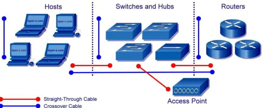
Straight-Through Cable:
Straight-through means that the color of wire on Pin 1 on one end of the cable is the same as that of Pin 1 on the other end
Pin 2 is the same as Pin 2, and so on
UTP Cable Installation
UTP Cable Configurations
Crossover Cable:
A crossover cable means that the second and third pairs on one end of the cable will be reversed on the other end
The pin-outs are T568A on one end and T568B on the other end
If the crossover cable is used between switches, it's considered to be part of the "vertical" cabling
Vertical cabling is also called backbone cabling
A crossover cable can be used as a backbone cable to connect two or more switches in a LAN, or to connect two isolated hosts to create a mini-LAN
Difference b/w crossover and Straight through cable
•
Crossover Cable:-
A crossover cable is used to connect two computers, two hubs , two routers ect. A cross over cable is used to connect two similar devices eg.two computers.
In the crossover cable the wires linking the pins are crisscrossed,
•
Straight through
Cable:- A straight through cable is used to connect a computer to a router a switch or hub.
A straight through cable is used to connect two dissimilar devices. eg.a computer and a switch.
it is not possible two link two computers with only a straight through cable.
UTP Cable Installation
UTP Cable Installation
UTP Cable Configurations
Rollover Cable:
A rollover cable can be used to connect a host or dumb terminal to the console port on the back of a router or switch.
Cable is called a rollover because the pins on one end are all reversed on the other end as though one end of the cable was rotated or rolled over.
UTP Cable Installation
Unguided Media
↗ For unguided media, transmission and reception are achieved by means of an Antenna
↗ For transmission, the antenna radiates electromagnetic energy into the medium (usually air), and for reception, the antenna picks up electromagnetic waves from the surrounding medium
There are basically two types of configurations for wireless transmission; directional and omnidirectional
↗ For the directional configuration, the transmitting antenna puts out a focused electromagnetic beam; the transmitting and receiving antennas must therefore be carefully aligned
Unguided Media
Three general ranges of frequencies are of interest in our discussion of wireless transmission.
1. Microwave
Unguided Media
Microwave
↗ Frequencies in the range of about 2 GHz to 40 GHz are referred to as microwave frequencies
↗ At these frequencies, highly directional beams are possible, and microwave is quite suitable for point-to-point transmission
↗ Microwave is also used for satellite communications
↗ Microwave is commonly used for both voice and television transmission
↗ A business can establish a microwave link to a long distance telecommunications facility in the same city, bypassing the local telephone company
Unguided Media
Broadcast Radio
↗ Frequencies in the range of 30 MHz to 1 GHz are suitable for omnidirectional applications and are referred to as the broadcast radio range
↗ This range is used for a number of data-networking applications
↗ The principal difference between broadcast radio and microwave is that the former is omnidirectional and the latter is directional
↗ Thus, broadcast radio does not require dish-shaped antennas, and the antennas need not be rigidly mounted to a precise alignment
Unguided Media
Infrared
↗ Another important frequency range, for local applications, is the infrared portion spectrum
↗ This covers, roughly, from 3 X 10¹¹ to 2 X 10¹⁴ Hz
↗ Infrared is useful to local point-to-point and multipoint applications within confined areas, such as a single room
↗ One important difference between infrared and microwave transmission is that the former does not penetrate walls
↗ Transceivers must be in line of sight of each other
↗ Thus, the security and interference problems encountered in microwave systems are not present