Electromagnetic Induction
and Faraday’s Law
590
C
H
A
P
T
E
R
CONTENTS
21–1 Induced EMF
21–2 Faraday’s Law of Induction; Lenz’s Law
21–3 EMF Induced in a Moving Conductor
21–4 Changing Magnetic Flux Produces an Electric Field 21–5 Electric Generators 21–6 Back EMF and Counter
Torque; Eddy Currents 21–7 Transformers and
Transmission of Power *21–8 Information Storage:
Magnetic and Semiconductor; Tape, Hard Drive, RAM *21–9 Applications of Induction:
Microphone, Seismograph, GFCI *21–10 Inductance
*21–11 Energy Stored in a Magnetic Field
*21–12 LRCircuit
*21–13 AC Circuits and Reactance *21–14 LRCSeries AC Circuit *21–15 Resonance in AC Circuits
CHAPTER-OPENING QUESTION—Guess now!
In the photograph above, the bar magnet is inserted down into the coil of wire, and is left there for 1 minute; then it is pulled up and out from the coil. What would an observer watching the galvanometer see?
(a) No change (pointer stays on zero): without a battery there is no current to detect.
(b) A small current flows while the magnet is inside the coil of wire. (c) A current spike as the magnet enters the coil, and then nothing.
(d) A current spike as the magnet enters the coil, and then a steady small current. (e) A current spike as the magnet enters the coil, then nothing (pointer at zero),
then a current spike in the opposite direction as the magnet exits the coil.
I
n Chapter 20, we discussed two ways in which electricity and magnetism are related: (1) an electric current produces a magnetic field; and (2) a magnetic field exerts a force on an electric current or on a moving electric charge. These discoveries were made in 1820–1821. Scientists then began to wonder: if electric currents produce a magnetic field, is it possible that a magnetic field can produce an electric current? Ten years later the American Joseph Henry (1797–1878) and the Englishman Michael Faraday (1791–1867) independently found that it was possible. Henry actually made the discovery first. But Faraday published his results earlier and investigated the subject in more detail. We now discuss this phenomenon and some of its world-changing applications including the electric generator.21
S S
S
0 +
10
–10
0 +
10
–10
I I
(b) (a)
0 +
10
–10
I I
N
N
(c)
I = 0
N
Magnet moves up toward coil ( in coil increasing)
Magnet moves
down
No movement
BB
( in coil decreasing)B
B
( in coil constant)
BB
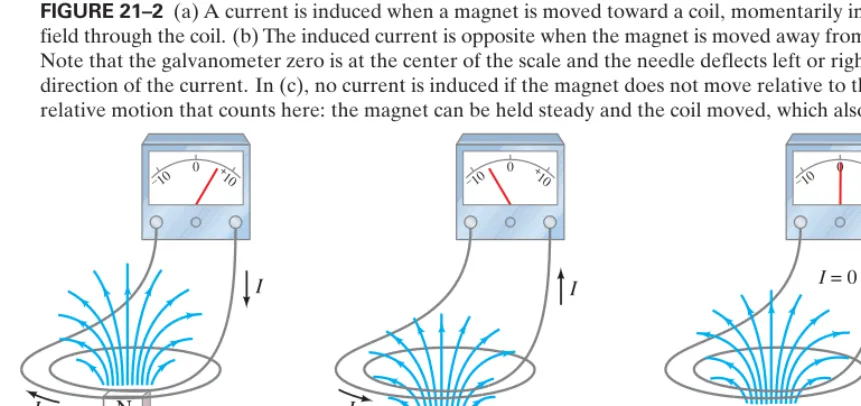
FIGURE 21–2 (a) A current is induced when a magnet is moved toward a coil, momentarily increasing the magnetic field through the coil. (b) The induced current is opposite when the magnet is moved away from the coil ( decreases). Note that the galvanometer zero is at the center of the scale and the needle deflects left or right, depending on the direction of the current. In (c), no current is induced if the magnet does not move relative to the coil. It is the relative motion that counts here: the magnet can be held steady and the coil moved, which also induces an emf.
BB –
+
0 +
10
–10
Switch
Battery
Iron
Galvanometer
X Y
FIGURE 21–1 Faraday’s experiment to induce an emf.
21–1
Induced EMF
In his attempt to produce an electric current from a magnetic field, Faraday used an apparatus like that shown in Fig. 21–1. A coil of wire, X, was connected to a battery. The current that flowed through X produced a magnetic field that was intensified by the ring-shaped iron core around which the wire was wrapped. Faraday hoped that a strong steady current in X would produce a great enough mag-netic field to produce a current in a second coil Y wrapped on the same iron ring.
C A U T I O N
Changing not itself, induces current
BB BB, This second circuit, Y, contained a galvanometer to detect any current but contained
no battery. He met no success with constant currents. But the long-sought effect was finally observed when Faraday noticed the galvanometer in circuit Y deflect strongly at the moment he closed the switch in circuit X. And the galvanometer deflected strongly in the opposite direction when he opened the switch in X. A constant current in X produced a constant magnetic field which produced nocurrent in Y. Only when the current in X was starting or stopping was a current produced in Y. Faraday concluded that although a constant magnetic field produces no current in a conductor, a changingmagnetic field can produce an electric current. Such a cur-rent is called an induced current. When the magnetic field through coil Y changes, a current occurs in Y as if there were a source of emf in circuit Y. We therefore say that
a changing magnetic field induces an emf.
Faraday did further experiments on electromagnetic induction, as this phenom-enon is called. For example, Fig. 21–2 shows that if a magnet is moved quickly into a coil of wire, a current is induced in the wire. If the magnet is quickly removed, a current is induced in the opposite direction ( through the coil decreases). Furthermore, if the magnet is held steady and the coil of wire is moved toward or away from the magnet, again an emf is induced and a current flows. Motion or change is required to induce an emf. It doesn’t matter whether the magnet or the coil moves. It is their relative motionthat counts.
BB
SECTION 21–1
591
C A U T I O NRelative motion—magnet
592
CHAPTER 21FARADAY’S LAW OF INDUCTION
FARADAY’S LAW OF INDUCTION
21–2
Faraday’s Law of Induction; Lenz’s Law
Faraday investigated quantitatively what factors influence the magnitude of the emf induced. He found first of all that the more rapidly the magnetic field changes, the greater the induced emf. He also found that the induced emf depends on the area of the circuit loop (and also the angle it makes with ). In fact, it is found that the emf is proportional to the rate of change of the magnetic flux, passing through the circuit or loop of area A. Magnetic flux for a uniform magnetic field through a loop of area Ais defined as
(21;1)
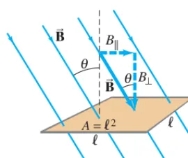
Here is the component of the magnetic field perpendicular to the face of the loop, and is the angle between and a line perpendicular to the face of the loop. These quantities are shown in Fig. 21–3 for a square loop of side whose area is When the face of the loop is parallel to and
When is perpendicular to the face of the loop, and
As we saw in Chapter 20, the lines of (like lines of ) can be drawn such that the number of lines per unit area is proportional to the field strength. Then the flux can be thought of as being proportional to the total number of lines passing through the area enclosed by the loop. This is illustrated in Fig. 21–4, where three wire loops of a coil are viewed from the side (on edge). For
no magnetic field lines pass through the loops and whereas is a maxi-mum when The unit of magnetic flux is the this is called aweber:
With our definition of flux, Eq. 21–1, we can write down the results of Faraday’s investigations: The emf induced in a circuit is equal to the rate of change of magnetic flux through the circuit:
(21;2a)
This fundamental result is known as Faraday’s law of induction, and it is one of the basic laws of electromagnetism.
If the circuit contains Nloops that are closely wrapped so the same flux passes through each, the emfs induced in each loop add together, so the total emf is
(21;2b)
[N loops]
e = –N ¢£¢tB.
[1loop]
e = – ¢£¢tB.
e
1Wb = 1T⭈m2.
tesla-meter2;
u = 0°.
£B £B = 0,
u = 90°,
£B
EB BB
[uniformBB⊥ loop face]
£B = BA.
u = 0°,
BB
£B = 0. BB, u = 90°
A = l2. l
BB
u B
B B⊥
[B uniform]
£B = B⊥A = BAcosu.
£B, BB
= 90°
θ
= 0
⌽B (a)
= 45°
θ
⌽B= BAcos 45°
(b)
= 0°
θ
=BA
⌽B (c)
BB
FIGURE 21–4 Magnetic flux is proportional to the number of lines of that pass through the loops of a coil (here with 3 loops).
BB
£B θ
θ B⊥ B||
l l
A=l2 BB BB
FIGURE 21–3 Determining the flux through a flat loop of wire. This loop is square, of side and area l A = l2.
EXERCISE A Return to the Chapter-Opening Question, page 590, and answer it again now. Try to explain why you may have answered differently the first time.
A loop of wire in a magnetic field. A square loop of wire
of side is in a uniform magnetic field What is the
mag-netic flux in the loop (a) when is perpendicular to the face of the loop and (b) when is at an angle of 30° to the area of the loop? (c) What is the magnitude of the average current in the loop if it has a resistance of and it is rotated from position (b) to position (a) in 0.14 s?
APPROACH We use the definition Eq. 21–1, to calculate the magnetic flux. Then we use Faraday’s law of induction to find the induced emf in the coil, and from that the induced current
SOLUTION The area of the coil is
(a) is perpendicular to the coil’s face, so and
or
(b) The angle is 30° and , so
or 3.5 * 10–4Wb, a bit less than in part (a).
£B = BAcosu = (0.16T)A2.5 * 10–3m2Bcos 30° = 3.5 * 10–4T⭈m2
cos 30° = 0.866
u
4.0 * 10–4Wb.
£B = BAcos 0° = (0.16T)A2.5 * 10–3m2B(1) = 4.0 * 10–4T⭈m2
u = 0°
BB
A = l2 = A5.0 * 10–2mB2
= 2.5 * 10–3m2. (I = e兾R).
£B = BAcosu,
0.012⍀
BB
BB
B = 0.16T.
l = 5.0cm
SECTION 21–2
593
(c) The magnitude of the induced emf (Eq. 21–2a) during the 0.14-s time interval isBefore and after the loop rotates, when it is at rest, the emf is zero. The current in the wire loop (Ohm’s law) while it is rotating is
I = eR = 3.6 * 10–4V
0.012⍀ = 0.030A = 30mA.
e = ¢£¢tB = A4.0 * 10
–4T⭈m2B - A3.5 * 10–4T⭈m2B
0.14s = 3.6 * 10
–4
V.
The minus signs in Eqs. 21–2a and b are there to remind us in which direction the induced emf acts. Experiments show that
a current produced by an induced emf moves in a direction so that the magnetic field created by that current opposes the original change in flux. This is known as Lenz’s law. Be aware that we are now discussing two distinct mag-netic fields: (1) the changing magmag-netic field or flux that induces the current, and (2) the magnetic field produced by the induced current (all currents produce a magnetic field). The second (induced) field opposes the changein the first.
Lenz’s law can be said another way, valid even if no current can flow (as when a circuit is not complete):
An induced emf is always in a direction that opposes the original change in flux that caused it.
Let us apply Lenz’s law to the relative motion between a magnet and a coil, Fig. 21–2. The changing flux through the coil induces an emf in the coil, produc-ing a current. This induced current produces its own magnetic field. In Fig. 21–2a the distance between the coil and the magnet decreases. The magnet’s magnetic field (and number of field lines) through the coil increases, and therefore the flux increases. The magnetic field of the magnet points upward. To oppose the upward increase, the magnetic field produced by the induced current needs to point downward inside the coil. Thus, Lenz’s law tells us the current moves as shown in Fig. 21–2a (use the right-hand rule). In Fig. 21–2b, the flux decreases(because the magnet is moved away and Bdecreases), so the induced current in the coil produces anupwardmagnetic field through the coil that is “trying” to maintain the status quo. Thus the current in Fig. 21–2b is in the opposite direction from Fig. 21–2a.
It is important to note that an emf is induced whenever there is a change in fluxthrough the coil, and we now consider some more possibilities.
C A U T I O N
Distinguish two different magnetic fields
I
(inward)
(a) (b)
Flux through coil is decreased becauseA decreased BB
FIGURE 21–5 A current can be induced by changing the coil’s area, even though Bdoesn’t change. Here the area Ais reduced by pulling on the sides of the coil: the fluxthrough the coil is reduced as we go from (a) to (b). The brief induced current acts in the direction shown so as to try to maintain the original flux by producing its own magnetic field into the page. That is, as area Adecreases, the current acts to increase Bin the original (inward) direction.
(£ = BA)
(inward)
Flux decreasing
(a) Maximum flux (b) Zero flux BB
FIGURE 21–6 A current can be induced by rotating a coil in a magnetic field. The flux through the coil changes from (a) to (b) because (in Eq. 21–1, ) went from 0°(cosu = 1)to 90°(cosu = 0).
£ = BAcosu
u
Magnetic flux so an emf can be induced in three ways:
(1) by a changing magnetic field B; (2) by changing the area Aof the loop in the field; or (3) by changing the loop’s orientation with respect to the field. Figures 21–1 and 21–2 showed case 1. Cases 2 and 3 are illustrated in Figs. 21–5 and 21–6.
u
594
CHAPTER 212. The magnetic field due to the induced current: (a) points in the same direction as the external field if the flux is decreasing; (b) points in the opposite direc-tion from the external field if the flux is increasing; or (c) is zero if the flux is not changing.
3. Once you know the direction of the induced magnetic field, use right-hand-rule-1 (page 563, Chapter 20) to find the direction of the induced current.
4. Always keep in mind that there are two magnetic fields: (1) an external field whose flux must be changing if it is to induce an electric current, and (2) a magnetic field produced by the induced current.
P
R
O
B
L
E
M
S
O
LV I
N G
Lenz’s Law
Lenz’s law is used to determine the direction of the (conventional) electric current induced in a loop due to a change in magnetic flux inside the loop. To produce an induced current you need
(a) a closed conducting loop, and
(b) an external magnetic flux through the loop that is changing in time.
1. Determine whether the magnetic flux
inside the loop is decreasing, increasing, or unchanged. (£B = BAcosu)
Practice with Lenz’s law. In which direc-tion is the current, induced in the circular loop for each situadirec-tion in Fig. 21–8?
RESPONSE In (a), the magnetic field initially pointing out of the page passes through the loop. If you pull the loop out of the field, magnetic flux through the loop decreases; so the induced current will be in a direction to maintain the decreasing flux through the loop: the current will be counterclockwise to produce a magnetic field outward (toward the reader).
(b) The external field is into the page. The coil area gets smaller, so the flux will decrease; hence the induced current will be clockwise, producing its own field into the page to make up for the flux decrease.
(c) Magnetic field lines point into the S pole of a magnet, so as the magnet moves toward us and the loop, the magnet’s field points into the page and is getting stronger. The current in the loop will be induced in the counterclock-wise direction in order to produce a field outof the page.
(d) The field is in the plane of the loop, so no magnetic field lines pass through the loop and the flux through the loop is zero throughout the process; hence there is no change in flux and no induced emf or current in the loop.
(e) Initially there is no flux through the loop. When you start to rotate the loop, the external field through the loop begins increasing to the left. To counteract this change in flux, the loop will have current induced in a counterclockwise direction so as to produce its own field to the right.
BB
CONCEPTUAL EXAMPLE 21;3
Induction stove. In an induction stove (Fig. 21–7), an ac current exists in a coil that is the “burner” (a burner that never gets hot). Why will it heat a metal pan, usually iron, but not a glass container?
RESPONSE The ac current sets up a changing magnetic field that passes through the pan bottom. This changing magnetic field induces a current in the pan, and since the pan offers resistance, electric energy is transformed to thermal energy which heats the pan and its contents. If the pan is iron, magnetic hysteresis due to the changing current produces additional heating. A glass container offers such high resistance that little current is induced and little energy is transferred AP = V2兾RB.
CONCEPTUAL EXAMPLE 21;2
(c)
S
S magnetic pole moving from below,
up toward the loop
(d)
S N
N magnetic pole moving toward loop
in the plane of the loop
(a)
Pulling a round loop to the right out of a magnetic
field which points out of the page
(b)
Shrinking a loop in a magnetic field pointing into the page
(e)
Rotating the loop by pulling the left side toward us and pushing the right side in; the magnetic field
points from right to left
BB
FIGURE 21–8 Example 21–3. FIGURE 21–7 Example 21–2: An induction stove.
C A U T I O N
Magnetic field created by induced current opposes change in external flux, not necessarily opposing
SECTION 21–2 Faraday’s Law of Induction; Lenz’s Law
595
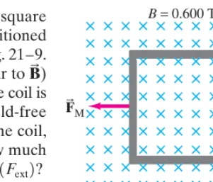
Pulling a coil from a magnetic field. A 100-loop squarecoil of wire, with side and total resistance is positioned perpendicular to a uniform magnetic field as shown in Fig. 21–9. It is quickly pulled from the field at constant speed (moving perpendicular to ) to a region where Bdrops abruptly to zero. At the right edge of the coil is at the edge of the field. It takes 0.100 s for the whole coil to reach the field-free region. Determine (a) the rate of change in flux through one loop of the coil, and (b) the total emf and current induced in the 100-loop coil. (c) How much energy is dissipated in the coil? (d) What was the average force required
APPROACH We start by finding how the magnetic flux,
changes during the time interval Faraday’s law then gives the induced emf and Ohm’s law gives the current.
SOLUTION (a) The coil’s area is The flux through one loop is initially
After 0.100 s, the flux is zero. The rate of change in flux is con-stant (because the coil is square), and for one loop is equal to
(b) The emf induced (Eq. 21–2) in the 100-loop coil during this 0.100-s interval is
The current is found by applying Ohm’s law to the coil:
By Lenz’s law, the current must be clockwise to produce more into the page and thus oppose the decreasing flux into the page.
(c) The total energy dissipated in the coil is the product of the power and the time:
(d) We can use the result of part (c) and apply the work-energy principle: the energy dissipated Eis equal to the work Wneeded to pull the coil out of the
field (Chapter 6). Because where then
Alternate Solution (d) We can also calculate the force directly using Eq. 20–2 for constant The force the magnetic field exerts on the top and bottom sections of the square coil of Fig. 21–9 are in opposite directions and cancel each other. The magnetic force exerted on the left vertical section of the square coil acts to the left as shown because the current is up (clockwise). The right side of the loop is in the region where Hence the external force to the right, needed to just overcome the magnetic force to the left (on ), is
which is the same answer, confirming our use of energy conservation above. Fext = NIlB = (100)(0.0150A)(0.0500m)(0.600T) = 0.0450N, N = 100loops
F B
ext,
BB = 0.
FBM BB, F = IlB.
fext = Wd =
2.25 * 10–3J
5.00 * 10–2m = 0.0450N.
d = 5.00cm,
W = fextd
E = Pt = I2Rt = A1.50 * 10–2AB2(100⍀)(0.100s) = 2.25 * 10–3J.
A= I2RB BB
I = e R =
1.50V
100⍀ = 1.50 * 10
–2A = 15.0mA.
100-⍀
e = –N ¢£¢tB = –(100)A–1.50 * 10–2Wb兾sB = 1.50V. ¢£B
¢t =
0 - A1.50 * 10–3WbB
0.100s = –1.50 * 10
–2Wb兾s.
1.50 * 10–3Wb.
A2.50 * 10–3m2B = £B = BA = (0.600T)
2.50 * 10–3m2. A = l2 = A5.00 * 10–2mB2 =
¢t = 0.100s.
£B = BAcos 0° = BA, (Fext)? t = 0,
BB
B = 0.600T,
R = 100⍀,
l = 5.00cm
EXAMPLE 21;4
EXERCISE B What is the direction of the induced current in the circular loop due to the current shown in each part of Fig. 21–10?
B= 0
M ext
B= 0.600 T
5.00 cm
F
B
FB
FIGURE 21–9 Example 21–4. The square coil in a magnetic field
is pulled abruptly to the right to a region where (The forces shown are discussed in the alternate solution at the end of Example 21–4.)
B= 0.
B = 0.600T
I constant
I increasing
(d) (c)
I decreasing
(b) (a)
I increasing
21–3
EMF Induced in a Moving Conductor
Another way to induce an emf is shown in Fig. 21–11a, and this situation helps illuminate the nature of the induced emf. Assume that a uniform magnetic field is perpendicular to the area bounded by the conductor and the movable rod resting on it. If the rod is made to move at a speed to the right, it travels a distance in a time Therefore, the area of the loop increases by an amount in a time By Faraday’s law there is an induced emf whose magnitude is given by(21;3)
The induced current is clockwise (to counter the increasing flux).
Equation 21–3 is valid as long as B, and are mutually perpendicular. (If they are not, we use only the components of each that are mutually perpendicular.) An emf induced on a conductor moving in a magnetic field is sometimes called motional emf. We can also obtain Eq. 21–3 without using Faraday’s law. We saw in Chapter 20 that a charged particle moving with speed perpendicular to a magnetic field B experiences a force (Eq. 20–4). When the rod of Fig. 21–11a moves to the right with speed the electrons in the rod also move with this speed. Therefore, since each electron feels a force which acts up the page as the red arrow in Fig. 21–11b shows. If the rod is not in contact with the conductor, electrons would collect at the upper end of the rod, leaving the lower end positive (see signs in Fig. 21–11b). There must thus be an induced emf. If the rod is in contact with the conductor (Fig. 21–11a), the electrons will flow into the There will then be a clockwise (conventional) current in the loop. To calculate the emf, we determine the work Wneeded to move a charge qfrom one end of the rod to the other against this potential difference:
The emf equals the work done per unit charge, so the same result as from Faraday’s law above, Eq. 21–3.
qvBl兾q = Blv,
e = W兾q = (qvB)(l). W = force * distance =
U.
U-shaped
U-shaped
F = qvB,
v B
⊥BB,
v,
F = qvB v
v l,
e = ¢£¢tB = B¢¢tA = Bl¢vt¢t = Blv.
e ¢A = l¢x = lv¢t ¢t.
¢t.
¢x = v¢t
v
U-shaped
BB
596
CHAPTER 21P H Y S I C S A P P L I E D
Blood-flowmeasurement
EXERCISE C In what direction will the electrons flow in Fig. 21–11 if the rod moves to the left, decreasing the area of the current loop?
Does a moving airplane develop a large emf? An airplane travels in a region where the Earth’s magnetic field is about and is nearly vertical (Fig. 21–12). What is the potential differ-ence induced between the wing tips that are 70 m apart?
APPROACH We consider the wings to be a 70-m-long conductor moving through the Earth’s magnetic field. We use Eq. 21–3 to get the emf.
SOLUTION Since and we have
NOTE Not much to worry about.
e = Blv = A5 * 10–5TB(70m)(280m兾s) L 1V. v
B ⊥BB,
v = 1000km兾h = 280m兾s, 5 * 10–5T
1000km兾h
EXAMPLE 21;5 ESTIMATE
Electromagnetic blood-flow measurement. The rate of blood flow in our body’s vessels can be measured using the apparatus shown in Fig. 21–13, since blood contains charged ions. Suppose that the blood vessel is 2.0 mm in diameter, the magnetic field is 0.080 T, and the measured emf is 0.10 mV. What is the flow velocity of the blood?
APPROACH The magnetic field points horizontally from left to right (N pole toward S pole). The induced emf acts over the width of the blood vessel, perpendicular to and (Fig. 21–13), just as in Fig. 21–11. We can then use Eq. 21–3 to get
SOLUTION We solve for in Eq. 21–3:
NOTE In actual practice, an alternating current is used to produce an alternating magnetic field. The induced emf is then alternating.
v = Bel = A1.0 * 10 –4
VB
(0.080T)A2.0 * 10–3mB = 0.63m兾s. v
v.
vB BB
l = 2.0mm
BB
v EXAMPLE 21;6
l
BB
vB
vB – (a)
(b)
(outward)
Force on electron t
ΔA
+ –
Δ
v
e
S Voltmeter
N
v
B
l
FIGURE 21–13 Measurement of blood velocity from the induced emf. Example 21–6.
FIGURE 21–12 Example 21–5. FIGURE 21–11 (a) A conducting rod is moved to the right on a
conductor in a uniform magnetic field that points out of the page. The induced current is clockwise. (b) Upward force on an electron in the metal rod (moving to the right) due to pointing out of the page; hence electrons can collect at the top of the rod, leaving
at the bottom.
± charge
BB BB
V
t
SECTION 21–5 Electric Generators
597
21–4
Changing Magnetic Flux
Produces an Electric Field
We have seen that a changing magnetic flux induces an emf. In a closed loop of wire there will also be an induced current, which implies there is an electric field in the wire causing the electrons to start moving. Indeed, this and other results suggest the important conclusion that
a changing magnetic flux produces an electric field.
This result applies not only to wires and other conductors, but is a general result that applies to any region in space. Indeed, an electric field will be produced
at any point in space where there is a changing magnetic field. We can get a simple formula for Ein terms of Bfor the case of electrons in a moving conductor, as in Fig. 21–11. The electrons feel a force (upwards in Fig. 21–11b); and if we put ourselves in the reference frame of the conductor, this force accelerating the electrons implies that there is an electric field in the conductor. Electric field is defined as the force per unit charge, where here (Eq. 20–4). Thus the effective field Ein the rod must be
(21;4)
which is a useful result.
21–5
Electric Generators
We discussed alternating currents (ac) briefly in Section 18–7. Now we examine how ac is generated: by an electric generatorordynamo. A generator transforms mechanical energy into electric energy, just the opposite of what a motor does (Section 20–10). A simplified diagram of an ac generatoris shown in Fig. 21–14. A generator consists of many loops of wire (only one is shown) wound on an armaturethat can rotate in a magnetic field. The axle is turned by some mechan-ical means (falling water, steam turbine, car motor belt), and an emf is induced in the rotating coil. An electric current is thus the outputof a generator. Suppose in Fig. 21–14 that the armature is rotating clockwise; then right-hand-rule-3 (p. 568) applied to charged particles in the wire (or Lenz’s law) tells us that the (conventional) current in the wire labeled b on the armature is outward towards us; therefore the current is outward through brush b. (Each brush is fixed and presses against a continuous slip ring that rotates with the armature.) After one-half revolution, wire b will be where wire a is now in Fig. 21–14, and the current then at brush b will be inward. Thus the current produced is alternating.
The frequency fis 60 Hz for general use in the United States and Canada, whereas 50 Hz is used in many countries. Most of the power generated in the United States is done at steam plants, where the burning of fossil fuels (coal, oil, natural gas) boils water to produce high-pressure steam that turns a turbine connected to the generator axle (Fig. 15–21). Turbines can also be turned by water pressure at a dam (hydroelectric). At nuclear power plants, the nuclear energy released is used to produce steam to turn turbines. Indeed, a heat engine (Chapter 15) connected to a generator is the principal means of generating electric power. The frequency of 60 Hz or 50 Hz is maintained very precisely by power companies.
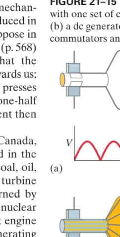
A dc generator is much like an ac generator, except the slip rings are replaced by split-ring commutators, Fig. 21–15a, just as in a dc motor (Figs. 20–37 and 20–38). The output of such a generator is as shown and can be smoothed out by placing a capacitor in parallel with the output.† More common is the use of
many armature windings, as in Fig. 21–15b, which produces a smoother output. E = Fq = qvqB = vB,
F = qvB E = F兾q,
(= induced)
†A capacitor tends to store charge and, if the time constant RC is long enough, helps to smooth out the voltage as shown in the figure to the right.
I
I I
I
Brushes
Slip rings Axle rotated
mechanically
N S
a b Armature
a b
FIGURE 21–14 An ac generator.
(b) V
t (a)
V
t
Alternators
Automobiles used to use dc generators. Today they mainly use alternators, which avoid the problems of wear and electrical arcing (sparks) across the split-ring commutators of dc generators. Alternators differ from generators in that an electro-magnet, called the rotor, is fed by current from the battery and is made to rotate by a belt from the engine. The magnetic field of the turning rotor passes through a surrounding set of stationary coils called the stator (Fig. 21–16), inducing an alternating current in the stator coils, which is the output. This ac output is changed to dc for charging the battery by the use of semiconductor diodes, which allow current flow in one direction only.
Deriving the Generator Equation
Figure 21–17 shows the wire loop on a generator armature. The loop is being made to rotate clockwise in a uniform magnetic field The velocity of the two lengths ab and cd at this instant are shown. Although the sections of wire bc and da are moving, the force on electrons in these sections is toward the side of the wire, not along the wire’s length. The emf generated is thus due only to the force on charges in the sections ab and cd. From right-hand-rule-3, we see that the direc-tion of the induced current in ab is from a toward b. And in the lower secdirec-tion, it is from c to d; so the flow is continuous in the loop. The magnitude of the emf generated in ab is given by Eq. 21–3, except that we must take the component of the velocity perpendicular to B:
where is the length of ab. From Fig. 21–17 we see that where is the angle the loop’s face makes with the vertical. The emf induced in cd has the same magnitude and is in the same direction. Therefore their emfs add, and the total emf is
where we have multiplied by N, the number of loops in the coil.
If the coil is rotating with constant angular velocity then the angle From the angular equations (Eq. 8–4), where ris the distance from the rotation axis and his the length of bc or ad. Thus or (21;5) where A = lh is the area of the loop. This equation holds for any shape coil, not just
e = NBvAsinvt,
e = 2NBvl(h兾2)sinvt,
v=vr=v(h兾2),
u = vt.
v,
e = 2NBlvsinu,
u
v⊥ = vsinu, l
e = Blv⊥,
BB.
*
598
CHAPTER 21N
I(induced)
θ θ
a
⊥
b
c
d Axis
I(induced) S
BB v
B
vB v
B
FIGURE 21–17 The emf is induced in the segments ab and cd, whose velocity components perpendicular to the field areBB vsinu.
S Current to
produce
B field N
(Rotating electromagnet) S
Slip rings Engine
belt Engine
belt
(a)
(b)
Output current (induced) Loops of wire
(in which current is induced)
Stator assembly Stator coil (emf induced in)
Stator coil (emf induced in)
Input current
South pole
North pole
Coil (producesB) Slip
rings
Rotor
Rotates S
S
S N N
N
FIGURE 21–16 (a) Simplified schematic diagram of an alternator. The input current to the rotor from the battery is connected through continuous slip rings. Sometimes the rotor electromagnet is replaced by a permanent magnet (no input current). (b) Actual shape of an alternator. The rotor is made to turn by a belt from the engine. The current in the wire coil of the rotor produces a magnetic field inside it on its axis that points horizontally from left to right (not shown), thus making north and south poles of the plates attached at either end. These end plates are made with triangular fingers that are bent over the coil—hence there are alternating N and S poles quite close to one another, with magnetic field lines between them as shown by the blue lines. As the rotor turns, these field lines pass through the fixed stator coils (shown on the right for clarity, but in operation the rotor rotates within the stator), inducing a current in them, which is the output.
P H Y S I C S A P P L I E D
SECTION 21–6
599
for a rectangle as derived. Thus, the output emf of the generator is sinusoidallyalter-nating (see Fig. 21–18 and Section 18–7). Since is expressed in radians per second, we can write where fis the frequency (in ). The rms output (see Section 18–7, Eq. 18–8b) is
Vrms =
NBvA 22
.
Hz = s–1
v = 2pf,
v
An ac generator. The armature of a 60-Hz ac generator rotates in a 0.15-T magnetic field. If the area of the coil is how many loops must the coil contain if the peak output is to be
APPROACH From Eq. 21–5 we see that the maximum emf is
SOLUTION We solve Eq. 21–5 for Nwith
N = e0 BAv =
170V
(0.15T)A2.0 * 10–2m2BA377s–1B = 150turns.
v = 2pf = (6.28)A60s–1B = 377s–1:
e0 = NBAv.
e0 = 170V?
2.0 * 10–2m2, EXAMPLE 21;7
21–6
Back EMF and Counter Torque;
Eddy Currents
Back EMF, in a Motor
A motor turns and produces mechanical energy when a current is made to flow in it. From our description in Section 20–10 of a simple dc motor, you might expect that the armature would accelerate indefinitely due to the torque on it. However, as the armature of the motor turns, the magnetic flux through the coil changes and an emf is generated. This induced emf acts to oppose the motion (Lenz’s law) and is called the back emforcounter emf. The greater the speed of the motor, the greater the back emf. A motor normally turns and does work on something, but if there were no load to push (or rotate), the motor’s speed would increase until the back emf equaled the input voltage. When there is a mechanical load, the speed of the motor may be limited also by the load. The back emf will then be less than the external applied voltage. The greater the mechanical load, the slower the motor rotates and the lower is the back emf (e r v, Eq. 21–5).
Back emf in a motor. The armature windings of a dc motor have a resistance of The motor is connected to a 120-V line, and when the motor reaches full speed against its normal load, the back emf is 108 V. Calculate (a) the current into the motor when it is just starting up, and (b) the current when the motor reaches full speed.
APPROACH As the motor is just starting up, it is turning very slowly, so there is negligible back emf. The only voltage is the 120-V line. The current is given by Ohm’s law with At full speed, we must include as emfs both the 120-V applied emf and the opposing back emf.
SOLUTION (a) At start up, the current is controlled by the 120 V applied to the coil’s resistance. By Ohm’s law,
(b) When the motor is at full speed, the back emf must be included in the equivalent circuit shown in Fig. 21–19. In this case, Ohm’s law (or Kirchhoff’s rule) gives
Therefore
NOTE This result shows that the current can be very high when a motor first starts up. This is why the lights in your house may dim when the motor of the refrigerator (or other large motor) starts up. The large initial refrigerator current causes the voltage to the lights to drop because the house wiring has resistance and there is some voltage drop across it when large currents are drawn.
I = 12V
5.0⍀ = 2.4A. 120V - 108V = I(5.0⍀).
I = VR = 120V
5.0⍀ = 24A. 5.0-⍀
R = 5.0⍀. 5.0⍀.
EXAMPLE 21;8
Time emf
0
e0
FIGURE 21–18 An ac generator produces an alternating current. The
output emf where
(Eq. 21–5). e0= NAvB
e= e0sinvt,
Windings of motor
5.0Ω
Back emf induced in armature winding
induced= 108 V
= 120 V
e e
600
CHAPTER 21 Electromagnetic Induction and Faraday’s LawP H Y S I C S A P P L I E D
Burning out a motor
(a)
(b)
(inward)
c
e d FB
BB
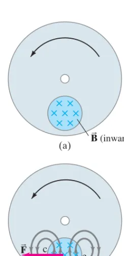
FIGURE 21–20 Production of eddy currents in a rotating wheel. The gray lines in (b) indicate induced current.
Motor overload. When using an appliance such as a blender, electric drill, or sewing machine, if the appliance is overloaded or jammed so that the motor slows appreciably or stops while the power is still connected, the motor can burn out and be ruined. Explain why this happens.
RESPONSE The motors are designed to run at a certain speed for a given applied voltage, and the designer must take the expected back emf into account. If the rotation speed is reduced, the back emf will not be as high as expected ( Eq. 21–5). The current will increase and may become large enough that the windings of the motor heat up and may melt, ruining the motor.
e r v,
CONCEPTUAL EXAMPLE 21;9
Counter Torque, in a Generator
In a generator, the situation is the reverse of that for a motor. As we saw, the mechanical turning of the armature induces an emf in the loops, which is the output. If the generator rotates but is not connected to an external circuit, the emf exists at the terminals but there is no current. In this case, it takes little effort to turn the armature. But if the generator isconnected to a device that draws cur-rent, then a current flows in the coils of the armature. Because this current-carrying coil is in an external magnetic field, there will be a torque exerted on it (as in a motor), and this torque opposes the motion (use right-hand-rule-2, page 568, for the force on a wire in Fig. 21–14 or 21–17). This is called acounter torque. The greater the electrical load—that is, the more current that is drawn—the greater will be the counter torque. Hence the external applied torque will have to be greater to keep the generator turning. This makes sense from the conservation of energy principle. More mechanical energy input is needed to produce more electric energy output.
EXERCISE D A bicycle headlight is powered by a generator that is turned by the bicycle wheel. (a) If you speed up, how does the power to the light change? (b) Does the gener-ator resist being turned as the bicycle’s speed increases, and if so how?
Eddy Currents
Induced currents are not always confined to well-defined paths such as in wires. Consider, for example, the rotating metal wheel in Fig. 21–20a. An external mag-netic field is applied to a limited area of the wheel as shown and points into the page. The section of wheel in the magnetic field has an emf induced in it because the conductor is moving, carrying electrons with it. The flow of induced (conventional) current in the wheel is upward in the region of the magnetic field (Fig. 21–20b), and the current follows a downward return path outside that region. Why? According to Lenz’s law, the induced currents oppose the change that causes them. Consider the part of the rotating wheel labeled c in Fig. 21–20b, where the magnetic field is zero but is just about to enter a region where points into the page. To oppose this inward increase in magnetic field, the induced current is counterclockwise to produce a field pointing out of the page (right-hand-rule-1). Similarly, region d is about to move to e, where is zero; hence the current is clockwise to produce an inward field opposed to this decreasing flux inward. These currents are referred to as eddy currents. They can be present in any conductor that is moving across a magnetic field or through which the magnetic flux is changing.
In Fig. 21–20b, the magnetic field exerts a force on the induced currents it has created, and that force opposes the rotational motion. Eddy currents can be used in this way as a smooth braking device on, say, a rapid-transit car. In order to stop the car, an electromagnet can be turned on that applies its field either to the wheels or to the moving steel rail below. Eddy currents can also be used to dampen (reduce) the oscillation of a vibrating system, which is referred to as magnetic damping.
FB BB
SECTION 21–7 Transformers and Transmission of Power
601
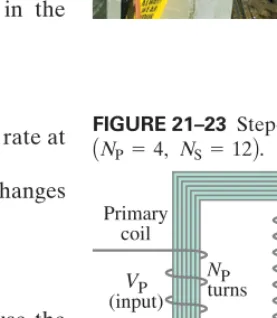
Eddy currents, however, can be a problem. For example, eddy currents inducedin the armature of a motor or generator produce heat and waste energy. To reduce the eddy currents, the armatures are laminated; that is, they are made of very thin sheets of iron that are well insulated from one another (used also in transformers, Fig. 21–23). The total path length of the eddy currents is confined to each slab, which increases the total resistance; hence the current is less and there is less wasted energy.
Walk-through metal detectors (Fig. 21–21) use electromagnetic induction and eddy currents to detect metal objects. Several coils are situated in the walls of the walk-through at different heights. In one technique, the coils are given brief pulses of current, hundreds or thousands of times per second. When a person passes through the walk-through, any metal object being carried will have eddy currents induced in it, and the small magnetic field produced by that eddy current can be detected, setting off an alert or alarm.
21–7
Transformers and
Transmission of Power
A transformer is a device for increasing or decreasing an ac voltage. Transformers are found everywhere: on utility poles (Fig. 21–22) to reduce the high voltage from the electric company to a usable voltage in houses (120 V or 240 V), in chargers for cell phones, laptops, and other electrical devices, in your car to give the needed high voltage to the spark plugs, and in many other applications. A transformer consists of two coils of wire known as the primary and secondary coils. The two coils can be interwoven (with insulated wire); or they can be linked by an iron core which is laminated to minimize eddy-current losses (Section 21–6), as shown in Fig. 21–23. Transformers are designed so that (nearly) all the mag-netic flux produced by the current in the primary coil also passes through the secondary coil, and we assume this is true in what follows. We also assume that energy losses (in resistance and hysteresis) can be ignored—a good approximation for real transformers, which are often better than 99%efficient.
When an ac voltage is applied to the primary coil, the changing magnetic field it produces will induce an ac voltage of the same frequency in the secondary coil. However, the voltage will be different according to the number of “turns” or loops in each coil. From Faraday’s law, the voltage or emf induced in the secondary coil is
where is the number of turns in the secondary coil, and is the rate at which the magnetic flux changes.
The input primary voltage, is related to the rate at which the flux changes through it,
where is the number of turns in the primary coil. This follows because the changing flux produces a back emf, in the primary that balances the applied voltage if the resistance of the primary can be ignored (Kirchhoff’s rules). We divide these two equations, assuming little or no flux is lost, to find
(21;6)
This transformer equationtells how the secondary (output) voltage is related to the primary (input) voltage; and in Eq. 21–6 can be the rms values (Section 18–7) for both, or peak values for both. Steady dc voltages don’t work in a transformer because there would be no changing magnetic flux.
VP VS
VS VP =
NS NP
.
VP
NP¢£B兾¢t, NP
VP = NP ¢£¢tB, VP,
¢£B兾¢t NS
VS = NS ¢£¢tB ,
(P = Ie)
P H Y S I C S A P P L I E D
Metal detector
FIGURE 21–22 Repairing a step-down transformer on a utility pole. FIGURE 21–21 Metal detector.
VS
(output) Primary
coil
Secondary coil
Laminated iron core
VP
(input)
NP
turns
NS
turns
602
CHAPTER 21 Electromagnetic Induction and Faraday’s LawTime 0
0
(a)
Time
(b)
Switch closed
Switch opened 12 V
10 kV
⫺10 kV
⫺20 kV
VS VP
FIGURE 21–24 A dc voltage turned on and off as shown in (a) produces voltage pulses in the secondary (b). Voltage scales in (a) and (b) are not the same.
If the secondary coil contains more loops than the primary coil
we have astep-up transformer. The secondary voltage is greater than the primary voltage. For example, if the secondary coil has twice as many turns as the primary coil, then the secondary voltage will be twice that of the primary voltage. If is less than we have astep-down transformer.
Although ac voltage can be increased (or decreased) with a transformer, we don’t get something for nothing. Energy conservation tells us that the power output can be no greater than the power input. A well-designed transformer can be greater than 99% efficient, so little energy is lost to heat. The power output thus essentially equals the power input. Since power (Eq. 18–5), we have
or (remembering Eq. 21–6),
(21;7)
IS IP =
NP NS
.
IPVP = ISVS,
P = IV NP,
NS
ANS 7 NPB,
P H Y S I C S A P P L I E D
Car ignition system
Cell phone charger. The charger for a cell phone contains a transformer that reduces 120-V (or 240-V) ac to 5.0-V ac to charge the 3.7-V battery (Section 19–4). (It also contains diodes to change the 5.0-V ac to 5.0-V dc.) Suppose the secondary coil contains 30 turns and the charger supplies 700 mA. Calculate (a) the number of turns in the primary coil, (b) the current in the primary, and (c) the power transformed.
APPROACH We assume the transformer is ideal, with no flux loss, so we can use Eq. 21–6 and then Eq. 21–7.
SOLUTION (a) This is a step-down transformer, and from Eq. 21–6 we have
(b) From Eq. 21–7
(c) The power transformed is
NOTE The power in the primary coil, is the
same as the power in the secondary coil. There is 100% efficiency in power transfer for our ideal transformer.
P = (0.029A)(120V) = 3.5W,
P = ISVS = (0.70A)(5.0V) = 3.5W. IP = ISNPNS = (0.70A)¢
30
720≤ = 29mA.
NP = NSVVP S =
(30)(120V)
(5.0V) = 720turns.
EXAMPLE 21;10
EXERCISE E How many turns would you want in the secondary coil of a transformer havingNP = 400 turnsif it were to reduce the voltage from 120-V ac to 3.0-V ac?
SECTION 21–7 Transformers and Transmission of Power
603
12,000 V 240,000 V 7200 V 240 V Power
plant
Step-up transformer
Step-down transformer (substation)
Step-down transformer
Home High voltage
transmission line
FIGURE 21–25 The transmission of electric power from power plants to homes makes use of transformers at various stages.
P H Y S I C S A P P L I E D
Transformers help power transmission
Transformers play an important role in the transmission of electricity. Power plants are often situated some distance from metropolitan areas, so electricity must then be transmitted over long distances (Fig. 21–25). There is always some power loss in the transmission lines, and this loss can be minimized if the power is transmitted at high voltage, using transformers, as the following Example shows.
Transmission lines. An average of 120 kW of electric power is sent to a small town from a power plant 10 km away. The transmission lines have a total resistance of Calculate the power loss if the power is transmitted at (a) 240 V and (b) 24,000 V.
APPROACH We cannot use because if Ris the resistance of the transmission lines, we don’t know the voltage drop along them. The given voltages are applied across the lines plus the load (the town). But we can determine the currentIin the lines and then find the power loss from for both cases (a) and (b).
SOLUTION (a) If 120 kW is sent at 240 V, the total current will be
The power loss in the lines, is then
Thus, over 80%of all the power would be wasted as heat in the power lines! (b) If 120 kW is sent at 24,000 V, the total current will be
The power loss in the lines is then
which is less than of 1%: a far better efficiency.
NOTE We see that the higher voltage results in less current, and thus less power is wasted as heat in the transmission lines. It is for this reason that power is usually transmitted at very high voltages, as high as 700 kV.
1 100
PL = I2R = (5.0A)2(0.40⍀) = 10W, I = PV = 1.2 * 10
5
W
2.4 * 104V = 5.0A.
PL = I2R = (500A)2(0.40⍀) = 100kW. PL,
I = PV = 1.2 * 10 5
W
2.4 * 102V = 500A.
PL = I2R, (= P兾V),
P = V2兾R
0.40⍀.
EXAMPLE 21;11
The great advantage of ac, and a major reason it is in nearly universal use†, is
that the voltage can easily be stepped up or down by a transformer. The output voltage of an electric generating plant is stepped up prior to transmission. Upon arrival in a city, it is stepped down in stages at electric substations prior to distri-bution. The voltage in lines along city streets is typically 2400 V or 7200 V and is stepped down to 240 V or 120 V for home use by transformers (Figs. 21–22 and 21–25).
604
CHAPTER 21Wireless Transmission of Power—Inductive Charging
Many devices with rechargeable batteries, like cell phones, cordless phones, and even electric cars, can be recharged using a direct metal contact between the device and the charger. But devices can also be charged “wirelessly” by induction, with-out the need for exposed electric contacts. The electric toothbrush shown in Fig. 21–26 sits on a plastic base. Inside the base is a “primary coil” connected to an ac outlet. Inside the toothbrush is a “secondary coil” in which a current is induced due to the changing magnetic field produced by the changing current in the primary coil. The current induced in the secondary coil charges the rechargeable batteries. (Not an option for ordinary AA or AAA batteries which are notrechargeable.) The effect is like a transformer—except here there is no iron to contain the field lines, so there is less efficiency. But you can separate the two parts (toothbrush and charger) and brush your teeth. Many heart pacemakers are given power inductively: power in an external coil is transmitted to a secondary coil in the pacemaker (Fig. 19–25) inside the person’s body near the heart. Inductive charging is also a possible means for recharging an electric car’s batteries.
Wireless transmission of power must be done over short distances to maintain a reasonable efficiency. Wireless transmission of signals (information) can be done over great distances (Section 22–7) because even fairly low power signals can be detected, and it is the information in the signal voltages that counts, not power.
21–8
Information Storage: Magnetic and
Semiconductor; Tape, Hard Drive, RAM
Magnetic Storage: Read/Write on Tape and Disks
Recording and playback on tape or disk is done by magnetic heads.Magnetic tapes contain a thin layer of ferromagnetic oxide on a thin plastic tape. Computer hard drives(HD) store digital information (applications and data): they have a thin layer of ferromagnetic material on the surface of each rotating disk or platter, Fig. 21–27a. During recording of an audio or video signal on tape, or “writing” on a hard drive, the voltage is sent to the recording head which acts as a tiny electromagnet (Fig. 21–27b) that magnetizes the tiny section of tape or disk pass-ing the narrow gap in the head at each instant. Durpass-ing playback, or “readpass-ing” of an HD, the changing magnetism of the moving tape or disk at the gap causes corresponding changes in the magnetic field within the soft-iron head, which in turn induces an emf in the coil (Faraday’s law). This induced emf is the output signal that can be processed by the computer, or for audio can be amplified and sent to a loudspeaker (for video to a monitor or TV).
*
*
Audio and video signals may be analog, varying continuously in amplitude over time: the variation in degree of magnetization at sequential points reflects the varia-tion in amplitude and frequency of the audio or video signal. In modern equipment, analog signals (say from a microphone) are electronically converted to digital—which means a series of bits, each of which is a “1” or a “0”, that forms abinary code as discussed in Section 17–10. (Recall also, 8 bits in a row 1 byte.) Computers process only digital information.
=
I⫽I0sin 2pft d
Secondary coil (in toothbrush) Primary coil (in charger base)
FIGURE 21–26 This electric toothbrush contains rechargeable batteries which are being recharged as it sits on its base. Charging occurs from a primary coil in the base to a secondary coil in the toothbrush. The toothbrush can be lifted from its base when you want to brush your teeth.
P H Y S I C S A P P L I E D
Charging phones, cars, etc., by
induction
Coil
Gap Read/Write
head
Moving magnetic tape or rotating disk
(b) (a)
Electric signal input (or output)
FIGURE 21–27 (a) Photo of a hard drive showing several platters and read write heads that can quickly move from the edge of the disk to the center. (b) Read Write
(playback recording) head for disk or tape. In writing or recording, the electric input signal to the head, which acts as an electromagnet, magnetizes the passing tape or disk. In reading or playback, the changing magnetic field of the passing tape or disk induces a changing magnetic field in the head, which in turn induces in the coil an emf that is the output signal.
兾 兾
兾
P H Y S I C S A P P L I E D
*SECTION 21–8
605
CD-ROMs, CDs (audio compact discs), and DVDs (digital video discs) are readby an optical drive(not magnetic): a laser emits a narrow beam of light that reflects off the “grooves” of the rotating disc containing “pits” as described in Section 28–11.
Semiconductor Memory: DRAM, Flash
Basic to your computer is its random access memory (RAM). This is where the information you are working with at any given time is temporarily stored and manipulated by you. Each data storage location can be accessed and read (or written) directly and quickly, so you don’t have to wait. In contrast, hard drives, tape, flash and external devices are more permanent storage, and they are much slower to access because the data must be searched for, sequentially, such as along the circular tracks of hard drives (Fig. 21–27a). Programs, applications, and data that you want to use are imported by the computer into the RAM from their more permanent (and more slowly accessed) storage area.†
RAM is based on semiconductor technology, storing the binary bits (“0” or “1”) as electric charge or voltage. Some computers may use semiconductors also for long-term storage (“flash memory”) in place of a hard drive.
A common type of RAM is dynamic random access memoryorDRAM, which uses arrays of transistors known as MOSFETs (metal-oxide semiconductor field-effect transistors). Transistors will be discussed in Section 29–10, but we already encountered them in Section 17–11 about TV screen addressing, Fig. 17–34, which we show again here, Fig. 21–28. A MOSFET transistor in RAM serves basically as an on–off switch: the voltage on the gateterminal acts to control the conductivity between the sourceand the drainterminals, thus allowing current to flow (or not) between them.
Each memory “cell,” which in DRAM consists of one transistor and a capacitor, stores one bit ( a “0” or a “1”). Each cell is extremely small physically, less than 100 nm across.‡ Typical DRAM chips (integrated circuits) contain billions of
these memory cells. To see how they work, we look at a tiny part, the simple four-cell array shown in Fig. 21–29. One side of each cell capacitor is grounded; the other side is connected to the transistor source. The drain of each transistor is connected to a very thin conducting wire or “line,” a bit-line, that runs across the array of cells. Each gate is connected to aword-line. A particular bit is a “1” or a “0” depending on whether the capacitor of the cell is charged to a voltage V (maybe 5 V) or is at zero (uncharged, or at a very small voltage).
To writedata, say on the upper left cell in Fig. 21–29, word-line-1 is given a high enough pulse of voltage to “turn on” the transistor. That is, the high gate voltage attracts charge and allows bit-line-1 and the capacitor to be connected. Thus charge can flow from bit-line-1 to the capacitor, charging it either to Vor to 0, depending on the bit-line-1 voltage at that moment, thus writing a “1” or a “0”.
The lower left cell in Fig. 21–29 can be written at the same time by setting bit-line-2 voltage to Vor zero.
Now let us see a simple way to reada cell. In order to read the data stored (“1” or “0”) on the upper left cell, a voltage of about is given to bit-line-1. Then word-line-1 is given enough voltage to turn on the transistor and connect bit-line-1 to the capacitor. The capacitor, if uncharged ( “0”), will now drag charge from bit-line-1 and the bit-line voltage will drop below If the capacitor is already charged to ( “1”), the connection to bit-line-1 will raise bit-line-1’s voltage to above A sensor at the end of bit-line-1 will detect either change in voltage (increase means it reads a “1”, decrease a “0”). All cells connected to one word-line are read at the same moment. The capacitor voltage has been altered by the small charge flow during the reading process. So that cell or bit which has just been read needs to be written again, or “refreshed.”
1 2V.
= V
1 2V. = 1 2V =
*
†Computer specifications may use “memory” for the random access (fast) memory, and “storage” for the long-term (and slower access) information on hard drives, flash drives, and related devices. ‡At 100 nm, bits can fit along a 1-cm line, So a square, 1 cm on a side, can hold (gigabyte). Today, cells are even smaller than 100 nm: a (30nm)2cell can hold L10GBin a 1 cm2area.
105* 105= 1010=10Gbits( L 1GB
1cm兾100nm) = 10–2m兾10–7m. 105
P H Y S I C S A P P L I E D
CDs and DVDs
FIGURE 21–28 Symbol for a MOSFET transistor. The gate acts to attract or repel charge, and thus open or close the connection along the semiconductor that connects source and drain.
Gate
Drain
Source
Word-line 1
C C
C C
Bit-line 1
Bit-line 2
Word-line 2
FIGURE 21–29 A tiny cell, part of a simple DRAM array. The word-lines and bit-lines do not touch each other where they cross.
606
CHAPTER 21 Electromagnetic Induction and Faraday’s LawThe transistors are imperfect switches and allow the charge on the tiny capac-itors in each cell to be “leaky” and lose charge fairly quickly, so every cell has to be read and rewritten (refreshed) many times per second. The D in DRAM stands for this “dynamic” refreshing action. If the power is turned off, the capacitors lose their charge and the data are lost. DRAM is thus referred to as being volatile memory, whereas a hard drive keeps its (magnetic) memory even when the electric power is off and is called nonvolatilememory (doesn’t “evaporate”).
Flash memoryis also made of semiconductor material on tiny “chips.” The transistor structures are more complicated, and are able to keep the data even without power so they are nonvolatile. Each MOSFET contains a second gate (the floating gate) insulated on both faces, and can hold charge for many years. Charged or not corresponds to a “1” or a “0” bit. Figure 21–30 is a diagram of such an NVM(nonvolatile memory) cell. The floating gate is insulated from the standard gate and the semiconductor connecting source and drain. A high posi-tive voltage on the gate forces electrons in the semiconductor (at 0 V) to pass through the thin insulator into the floating gate by a process of quantum mechanicaltunneling(discussed in Section 30–12). This charge is stored on the floating gate as a “1” bit. The erase process is done by applying the opposite voltage to force electrons to tunnel out of the floating gate, returning it to the uncharged state ( a “0” bit). The erase process is slow (milliseconds vs. ns for DRAM), so erasure is done in large blocks of memory. Flash memory† is
slower to read or write, and is too slow to use as RAM. Instead, flash memory can be used in place of a hard drive as general storage in computers and tablets, and may be called a “solid state device” (SSD). Flash is also used for flash drives, memory cards (such as SD cards), thumb drives, cell phone and portable player memory, and external computer memory.
Magnetoresistive RAM (MRAM) is a recent development, involving (again) magnetic properties. One cell (storing one bit) consists of two tiny ferromagnetic plates (separated by an insulator), one of which is permanently magnetized. The other plate can be magnetized in one direction or the other, for a “1” or a “0”, by current in nearby wires. Cell size is a bit large, but MRAM is fast and nonvolatile (no power and no refresh needed) and therefore has the potential to be used as any type of memory.
21–9
Applications of Induction:
Microphone, Seismograph, GFCI
Microphone
The condenser microphone was discussed in Section 17–7. Many other types operate on the principle of induction. In one form, a microphone is just the inverse of a loud-speaker (Section 20–10). A small coil connected to a membrane is suspended close to a small permanent magnet, as shown in Fig. 21–31. The coil moves in the magnetic field when sound waves strike the membrane, and this motion induces an emf in the moving coil. The frequency of the induced emf will be just that of the impinging sound waves, and this emf is the “signal” that can be amplified and sent to loudspeakers or recorder.
Credit Card Reader
When you pass a credit card through a reader at a store, the magnetic stripe on the back of the card passes over a read head just as for a computer hard drive. The magnetic stripe contains personal information about your account and connects by telephone line for approval from your credit card company. Newer cards use semiconductor chips that are more difficult to fraudulently copy.
*
*
*
= (–20V)
(±20V)
P H Y S I C S A P P L I E D
Credit card Membrane Small coil of wire
To recorder or amplifier
N S
Magnet
FIGURE 21–31 Diagram of a microphone that works by induction.
Semiconductor
Drain Floating gate
Gate
Source Thin insulator
Insulator
FIGURE 21–30 A floating gate nonvolatile memory cell (NVM).
†Why the name “Flash”? It may come from the erase process: large blocks erased “in a flash,” and or because the earliest floating gate memories were erased by a flash of UV light which ejected the stored electrons.
*SECTION 21–9 Applications of Induction: Microphone, Seismograph, GFCI
607
120 V Hot Neutral Power lines
Iron ring Sensing
coil
Solenoid circuit breaker
Electric circuit with one or more devices (possible sources of trouble) Simple electronic circuit
I
S
I I
I
FIGURE 21–33 A ground fault circuit interrupter (GFCI).
Electromagnetic induction is the physical basis of a GFCI. As shown in Fig. 21–33, the two conductors of a power line connected to an electric circuit or device (red) pass through a small iron ring. Around the ring are many loops of thin wire that serve as a sensing coil. Under normal conditions (no ground fault), the current moving in the hot power wire is exactly balanced by the returning current in the neutral wire. If something goes wrong and the hot wire touches the ungrounded metal case of the device or appliance, some of the entering current can pass through a person who touches the case and then to ground (a ground fault). Then the return current in the neutral wire will be less than the entering current in the hot wire, so there is a net currentpassing through the GFCI’s iron ring. Because the current is ac, it is changing and that current difference produces a changing magnetic field in the iron, thus inducing an emf in the sensing coil wrapped around the iron. For example, if a device draws 8.0 A, and there is a ground fault through a person of then 7.9 A will appear in the neutral wire. The emf induced in the sensing coil by this 100-mA difference is amplified by a simple transistor circuit and sent to its own solenoid circuit breaker that opens the circuit at the switch S, thus protecting your life.
If the case of the faulty device is grounded, the difference in current is even higher when there is a fault, and the GFCI trips very quickly.
GFCIs can sense current differences as low as 5 mA and react in 1 ms, saving lives. They can be small to fit as a wall outlet (Fig. 21–34a), or as a plug-in unit into which you plug a hair dryer or toaster (Fig. 21–34b). It is especially important to have GFCIs installed in kitchens, in bathrooms, outdoors, and near swimming pools, where people are most in danger of touching ground. GFCIs always have a “test” button (to be sure the GFCI itself works) and a “reset” button (after it goes off).
100mA(= 0.1A),
Suspension springs Coil
Permanent magnet
FIGURE 21–32 One type of seismograph, in which the coil is fixed to the case and moves with the Earth’s surface. The magnet, suspended by springs, has inertia and does not move instantaneously with the coil (and case), so there is relative motion between magnet and coil.
(a)
(b)
FIGURE 21–34 (a) A GFCI wall outlet. GFCIs can be recognized by their “test” and “reset” buttons. (b) Add-on GFCI that plugs into outlet.
P H Y S I C S A P P L I E D
GFCI
P H Y S I C S A P P L I E D
Seismograph
Seismograph
In geophysics, a seismographmeasures the intensity of earthquake waves using a magnet and a coil of wire. Either the magnet or the coil is fixed to the case, and the other is inertial (suspended by a spring; Fig. 21–32). The relative motion of magnet and coil when the surface of the Earth shakes induces an emf output.
Ground Fault Circuit Interrupter (GFCI)
Fuses and circuit breakers (Sections 18–6 and 20–7) protect buildings from electricity-induced fire, and apparatus from damage, due to undesired high cur-rents. But they do not turn off the current until it is very much greater than that which can cause permanent damage to humans or death If fast enough, they may protect humans in some cases, such as very high currents due to short circuits.A ground fault circuit interrupter(GFCI) is meant above all to protect humans.
(L100mA).
21–10
Inductance
Mutual Inductance
If two coils of wire are near one another, as in Fig. 21–35, a changing current in one will induce an emf in the other. We apply Faraday’s law to coil 2: the emf induced in coil 2 is proportional to the rate of change of magnetic flux passing through it. A changing flux in coil 2 is produced by a changing current in coil 1. So is proportional to the rate of change of the current in coil 1:
(21;8a)
where we assume the time interval is very small, and the constant of propor-tionality, M, is called the mutual inductance. (The minus sign is because of Lenz’s law, the induced emf opposes the changing flux.) Mutual inductance has units of which is called the henry(H), after Joseph Henry:
The mutual inductance M is a “constant” in that it does not depend on Mdepends on “geometric”