1
Numerical Methods in Civil Engineering
Developing numerical algorithm and a new program for simulating
alkali aggregate reaction in mass concrete
H. Mirzabozorg*, M.Lamea**
ARTICLE INFO Article history: Received: March 2014. Revised: September 2014. Accepted: October 2014. Keywords:
Alkali Aggregate Reaction, Concrete arch dams, Elastic module deterioration, Finite Element Method
Abstract:
Nowadays, Alkali Aggregate Reaction is considered as one of the most dangerous weak points of concrete and its occurrence has been widely reported in various structures. In the current study, a program is developed for predicting and examining the effects of mentioned reaction on the three-dimensional analysis of concrete structures such as arch dams. In this regard, a program provided for dam analysis is utilized applying necessary modifications on its flowchart to represent the reaction effects on the analysis procedure. The model utilized for simulating AAR is one of the comprehensive and newest models among the ones presented in various references. The deterioration of elasticity module due to the reaction is also included in the analyses, in addition to modeling concrete expansion with an excess load vector. The analyses conducted for considering the developed program capabilities indicates acceptable results so that its stability and accuracy are considered enough for long term prediction of performance of AAR-affected structures(especially concrete dams) during their service life.
1. Introduction
Although a couple of positive features encouraged the constructors to use concrete as suitable material but its weak points confronted them with new challenges. One of these problems is Alkali Aggregate Reaction (AAR) phenomenon. This phenomenon describes a chemical reaction that is occurred between existing alkali in concrete and some kinds of aggregate. Water, the inseparable part of concrete, acts as catalyst in progressing of this reaction. Swelling, creating micro cracks (that may turn into macro cracks) and the presence of gel outside the cracks can be mentioned as the apparent signs of this reaction. The damage resulting from this phenomenon has been reported in almost all hot and damp countries in the worlds. Moreover, the structures located directly in contact with water (such as bridge piers, concrete tanks and concrete dams) are the primary
* Associate Professor ,Civil Engineering Department,K.N.Toosi University of Technology, Tehran, Iran. , Email:mirzabozorg@kntu.ac.ir **Corresponding Author: PhD Student,Email: mo.l.civil@gmail.com
candidates for being impressed by the reaction. Meanwhile, most of them have not experienced successful results after repairing. All mentioned cases were sufficient for beginning vast investigations on AAR during the last few decades throughout the world. One of the most important and valuable branches of these investigations contains the modeling and predicting AAR effects by numerical methods and computer software. But it is evident that prerequisite of this field is providing the models which can simulate structural effects of the reaction. The proposed models for this reaction can be generally classified into micro models, meso models and macro models.
The last one is encompassing most of the common models in the structural analyses. The early models were somehow weak, but they have been gradually changed into accurate and modern models. New models can be reliably used for predictive analysis of various structures. Some of these models are presented in the following.
Thermal equivalency model (1999) is a simple one and easiest to acceptable use for common analyses [1];
Numerical Methods in Civil Engineering ,Vol. 1, No. 2,December.2014
however; it lacks kinetics components. Leger introduced a model which is both simple and comprehensive, but it lacks kinetics; moreover, it has not been widely used [1],[2]. The Model presented by Coussy; Ulm, Larrive; Li(1996) is a comprehensive kinetics model which is coupled with damage mechanics constitutive models. Saouma and perotti in 2006 presented a comprehensive anisotropic model in which chemistry (kinetics), physics (gel absorption by crack and effect of compression) and mechanics of concrete have been considered. Former applications of this model for structural analysis of AAR-affected concrete structures approve its high capabilities as well as its acceptable accuracy. Since the last model is the adopted one for the current study, it will be expanded in the following. AAR-affected concrete dams are of the most critical and important ones among various cases throughout the world. Therefore, the presented study focuses more profoundly on these structures. it should be mentioned that only some relevant phenomenological models have suitable consistency with concrete dam performance[1].
Considering various features, the model of Saouma and Perotti was chosen as a suitable one for the present research and was imported into the academic program called NSAD-DRI. The mentioned FE package can be counted on as one the powerful and fast programs for three-dimensional analysis of continuum concrete structures such as dams. It has been already verified through different articles and investigations [3]. Finally, a three dimensional concrete arch dam sample (Karaj Dam) has been selected as the case study for considering the results of the program and inspecting the structural effects of AAR.
2. An Overview to Nsad-Dri
NSAD-DRI is a program, previously developed to analyze mass concrete structure in three-dimensional space. The main focus of this program is on seismic analysis of arch dams. Its numerical scheme is Finite Element Method. The mathematical approach of this software is found as a fast and reliable one in comparison with similar finite element solvers. The main features of this program are as below [4]:
- Linear and nonlinear analyses in both static and dynamic loadings;
- Seismic 3D analysis of concrete dams with dam-reservoir-foundation interaction;
- Seismic fracture response of concrete dams; - Accounting for strain rate effects;
- Massed foundation interactions effects.
3. AAR Simulation
The model used to simulate AAR phenomenon contains the following presumptions.
AAR is a volumetric expansion and cannot be addressed individually along a principal direction without considering the other two orthogonal ones.
Temperature has significant effects on AAR; therefore, its temporal variation should be considered during an analysis.
AAR expansion is impressed by constraining due to compression and this is implemented in the utilized model by weight factors relevant to each principal direction.
Because of gel absorption by micro and macro cracks, high compressive and tensile stresses may inhibit AAR expansion. High compressive hydrostatic stresses slow down the reaction. Tri-axial compressive state of stress reduces expansion of AAR but not remove it.
A reduction in elasticity module and tensile strength is observed due to Alkali Aggregate Reaction, besides expansion.
The normalized expansion of reaction versus the time is presumed for the reaction progressing in the utilized model (Fig 1). The following Equation is projecting the pointed curve: (1) ) ( ) , , ( ) (
)
,
(
c c l c f I te
e
t
11
1
Fig.1: Reaction Progressive in constant temperature
AAR AAR
t
t
(
)
(
)
/
where, τl and τc are Latency and Characteristic time,
respectively, shown Fig 1. The following equations are used to obtain these parameters[5].
(2) (3)
)) 1 1 ( ( 0 )) 1 1 ( ( 0 0 0)
(
)
,
(
)
,
,
(
).
(
)
(
c c U l c c l U c ce
f
I
f
f
I
e
τl 2τc
ζ Time 1.0 0.0 0.2 0.4 0.6 0.8
3
Based on these equations, the references of temperature- (θ0), τc(θ0) and τl(θ0), are necessary for computing τc(θ) and τl(θ) at every arbitrary temperature and then δ is determined
at the corresponding time.Ul and Uc are activation energies
relevant to latency and characteristic time, respectively and are located in the following range:
(4)
k
U
k
U
c l500
5400
500
9400
Concrete inflation is the most important effect of AAR and is accurately considered in the utilized model. Temperature, humidity and state of stress, the most important factors impressing the expansion, are considered in the adopted model. Volumetric strain rate due to AAR is computed firstly as follows [5]:
0
).
,
(
).
(
).
,
(
).
,
(
)
(
1
t
tf
t
COD
cf
c
f
h
t
AAR vol
(5)
where, COD is crack opening displacement; ε∞ is maximum free volumetric expansion; and ζ is determined by Equation1.
The reductive factor due to lack of necessary humidity for reaction progressing is computed as:
(6) m
h
h
f
(
)
where, h is the relative humidity. Other features of the model such as absorbing gel by macro cracks (which have a reduction effect on reaction progressing) and distributing the resulted volumetric strain in the three principal directions (relevant to each Gaussian point) can be found in [5].
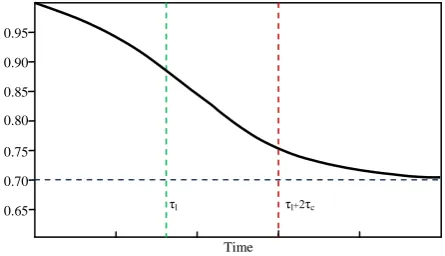
Tensile strength and elasticity modulus of the concrete are degraded and can be computed as below:
(7)
1
(
1
)
(
,
)
)
,
(
t
E
t
E
E(8)
1
(
1
)
(
,
)
)
,
(
t
f
,
t
f
t
t
Ewhere, E0 is and ft,0 are the original elastic modulus and
tensile strength, respectively; and βE and βf are their
corresponding residual fractional values, respectively, when εAAR tends to
AAR
. The mentioned degradation during the reaction progressing is shown in Fig 2.4. Finite Element Implementation
Equations 9 and 10 indicate the stress-strain relationship considering free strains (ε0) in the analysis procedure. Since
all performed analyses of present research are non-isothermal, ε0 contains both temperature and AAR
expansion.
Fig .2: Mechanical and strength properties degradation
(9)
[
D
]
(10)
AAR
TThen the strain energy of the element (e) is defined as
follows;
(11)
D dv
dv D dv D dv D dv D dv U AAR T AAR T AAR AAR T T AAR T AAR T AAR e ] [ 2 1 ] [ 2 1 ] [ 2 1 ] [ 2 1 } { } { ] [ } { } { 2 1 } { } { 2 1 ) 2 ( ) 1 (
Furthermore; (12)
eB
[
]
where,
e is degree of freedoms Vector for element (e); and [B] is strain-displacement matrix.Substituting Equation 12 for Equation 11and simplifying it will result in:
(13)
B D
dvdv D dv B D B U AAR T T e AAR T AAR e T T e e ] [ ] [ ] [ 2 1 ] ][ [ ] [ 2 1
Time 0.65 0.70 0.75 0.80 0.85 0.90 0.95τl τl+2τc
Numerical Methods in Civil Engineering ,Vol. 1, No. 2,December.2014
On the other side, considering the definition of stiffness matrix as:
(14)
K
e
[
B
]
T[
D
][
B
]
dv
potential energy of the element can be rewritten as follows:
(15)
e
e
W e T e U
e T e e e T e e e
eU W K F Const F
.
2 1
where,{Fe} is the element load vector. The added load
vector due to AAR is as follows:
(16)
F
B
D
AAR
dv
T
e
]
[
]
[
Minimizing potential energy results in:
(17)
e
e ee
F
F
K
The two later equations form the basis of programming for importing free strain effect in the current study. Other effects of AAR, deterioration of tensile strength and elastic modulus, should be considered too.
5. Programming of Numerical Algorithm
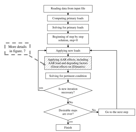
Hereby, all requirements have been provided to develop the desired finite element package (NSAD-DRI), for applying AAR effects during the analysis. The flowcharts of Figs 3 and 4 show the process of program running and position of AAR analysis in the applied procedure.
Fig .3: Finite element analysis flowchart
No
yes
No yes
Reading data from input file
Solving for primary loads
Beginning of step by step solution, step=0
Go to the next step Is new iteration
necessary? Applying new loads
Desirable steps are over?
Finish
Applying AAR effects, including AAR load and degrading factors
(Great effects on [D]matrix)
Solving for pertinent condition
More details
in figure. 7
Computing primary loads
5
Fig .4: AAR FE analysis flowchart6. Case Study
As mentioned before, dams are of the most important structures affected by AAR; so Amir Kabir Dam(Karaj Dam) has been selected as the case study for the developed program (Fig 5). This dam was constructed over Karaj River, flows nearby Tehran. The height of the dam from the foundation is about 180m and its height from the river bed is 161m. The crest length and width are about 390m and 7.85m, respectively. This dam has lived since1961.
No accurate test is done for identifying AAR occurrence in this dam. The present research is to evaluate Alkali Aggregate Reaction affecting this dam(with given features)as a sample of 3D analyses.
Fig .5: Downstream view of Amir Kabir arch dam
6.1. FE Analysis and AAR Effect
For seeking AAR effects in structural reactions of Amir Kabir Dam, a couple of analyses were conducted with and without considering the AAR occurrence. Both kinds of analyses were done, taking into account linear behavior (without cracking possibility during the analysis)for dam body during the analysis. Self-weight, hydrostatic pressure(because of water in dam reservoir)and temperature loads were common in all analyses. Meanwhile, the uplift has been neglected because of the small thickness of dam body in the dam-foundation interface. It is worth noting that in spite of considering linear behavior for the structure, this analysis is actually a nonlinear analysis because module of elasticity is updated due to AAR progressing in every time step of analysis.
For modeling the dam body in NSAD-DRI, a three dimensional cubic mesh with 72 iso-parametric elements and 592 nodes with three degrees of freedom (for each node)are implemented(Fig 6). It should be mentioned that there is only one element through the thickness of the dam body and galleries and other details are ignored.
Fig .6: FEM of the dam body
Reading AAR parameters from AAR block of input file (only at the
first arrival)
Computing free volumetric expansion due to AAR for each
GP
Computing degrading factors related to young's module and tensile strength for each GP
Computing weights for distributing volumetric expansion into main directions for each GP
Computing linear and shear strains considering directions related to DOFs for each GP
Computing AAR forces related to each DOF (in nodes)
Adding AAR forces to the total load vector
Reading stresses and strains and [D]matrix for each gauss point, resulting from previous loading and analysis
Reading temperature of nodes related to new step and computing temperature of GPs
Numerical Methods in Civil Engineering ,Vol. 1, No. 2,December.2014 E.L. 1660
E.L. 1768
temp.= 8 temp.= 13
The 20-node isoparametric “brick” finite element with 27 Gaussian Points is used to model the structure, geometrically. Fig 7shows this element and its node ordering.
Fig .7: 20 node iso-parametric element and node ordering The recorded stress free temperature follows the diagram in Fig 8[6].
Fig .8: Reference temperature in Amir Kabir arch dam[6]
The pertinent parameters for thermal and stress analyses(due to thermal condition)are taken as k=2.4m2/month and α=8.05×10⁻⁶/°C. The reservoir water surface is fluctuating between 136m and 164m which are in the annual operational range of the reservoir level. Whenever AAR effects are considered, the pertinent parameters for applying this reaction which are located in related block of the provided input data file are as below.
Uc=5400UL=9400βE=0.8βf=0.8 γt=0.18, Гr=0.1β=0.5
,ε=0.00284 , α=1.3333 ,θ0=333, τC0=2.7, τl0=5.5, σu=106,
fc=30.5×10⁶
Considering the parameters βf and βE, which are taken as
0.8 as well as the Equations 7and 8, it is clear that these parameters apply the effect of AAR on elastic modulus and tensile strength degradation. It is reminded that because there is not crack permission in the conducted analyses in the current article, the former parameter is not effective but the great effect of later parameter cannot be neglected. It’s worth noting that the presence of βE<1(that degrades
elasticity modulus) in the analysis algorithm makes the analyses nonlinear during which no cracking is permitted. Considering Saouma and Perotti researches on the efficiency of these parameters in the two dimensional analysis of a dam, AAR increases displacements and make the condition of stresses and strains much worse in comparison with those of usual loading over the dam body. It should be mentioned that in almost all ordinary programs of simulating AAR effects in concrete dams(such as ACRES GROW 3D[1]and CENT'S CANT[1]) model of Charlwood and Thompson is used in which this effect is not considered.
6.2. Interpretation of Analyses Results
Several analyses were performed to consider the program capabilities. Most of them, focused in the current study, consider AAR effects on the arch dams. The analyses were presented and compared here for two different conditions: one without AAR occurrence and the second (without cracking possibility) with AAR occurrence assumption. The features for usual loads are the same for both analyses. AAR is the only effect that makes difference between them. The results of these analyses were worked out as a couple of contours and diagrams. These analyses are presented separately in the following.
12 17
6
15 4
16 10 14
3 11 18
7 19
9 5
8
20
2 13
1
7
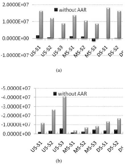
Fig 9 and 10: are presented as samples to show the considerabledifferences between the results of two performed analyses. It is clear that tensile and compressive stresses increase due to AAR occurrence. The tensile stresses can be seen after AAR occurrence, even in the cases having no tensile stresses with usual loading. In Fig 11 the effects of Alkali Aggregate Reaction are more distinguished in increasing the principal stresses and strains.
(a)
(b)
Fig. 11:Comparing the maximum and minimum principal stresses on upstream, downstream and middle face in two
inds of performed analyses
Because AAR occurrence is the only disagreement between these analyses, all other differences originate from AAR effect. The disagreement increases with the time; this claim can be proved through the diagram of “crest displacement vs. time”. The mentioned diagram is
considered as one of the most important approaches for identifying AAR occurrence in concrete dams. Figs. 16 and 17 show the vertical and horizontal crest displacements in upstream for both analyses. Considering these diagrams, there is not any differences between two analyses until step 170 (which is corresponding to month 170 of the dam service life). Therefore, there is not any witness of AAR occurrence in dam and dam follows its usual behavior. However, after then the dam behavior indicates the deviated displacements in the crest. It's worth noting that making changes in the displacement patterns over the dam body, which takes place beyond already predictions of AAR occurrence, may create dangerous condition about true locating and servicing of the installations in dams. It should be reminded that the crest displacement is treated as an important diagram for back analysis (for identifying undetermined AAR constitutive model parameters) or calibrating numerical models and pertinent software to achieve more reliable results in a dam.
Fig .13: Monthly variation of horizontal crest displacement with and without AAR effect
7. Conclusion
In this research, numerical modeling of Alkali Aggregate Reaction phenomenon in three-dimensional space was considered. It is clear that attaining the software with such a capability is very valuable for making decisions and predicting the behavior of AAR-affected
Numerical Methods in Civil Engineering ,Vol. 1, No. 2,December.2014
structures. For this reason, NSAD-DRI, which is known as a fast and powerful program in 3D analysis of concrete dams was selected as the reference code and its required parts were added for modeling the phenomenon. The selected phenomenological model that can model two structural aspects of the reaction, containing of making extra loads due to reaction and then simulating concrete properties deteriorations. This is the model of Saouma and Perotti, verified in several articles and researches[5], [7], [8], having strong scientific and experimental base sand. After developing the pointed out academic program, two analyses were conducted in order to consider the effect of alkali aggregate reaction on the structural behavior of arch dams and the results are provided as several contours and diagrams. Comparing these outputs in two distinguished conditions (with and without AAR) indicates clearly the impressive effect of Alkali Aggregate Reaction on the structural reactions of Arch dams. Keeping the results in view, AAR can considerably increase the value of principal stresses and strains in comparison with those of usual loadings. Besides, comparing the crest displacement diagrams shows that although until passing long time since the beginning of analysis, dam structural behavior is still almost ordinary. However, after certain step, the displacement diagram with AAR effect consideration starts making differences with the other one. The behavior that is concluded by the analyses of present research truly captures the reality in AAR-affected arch dams. These analyses implicates the importance of performing predictive analyses and necessary tests on AAR before constructing and even designing of concrete dams especially arch dams.
References
[1] Saouma, V. Xi, Yunping. "Literature Review of Alkali Aggregate Reaction in Concrete Dams", under contract from FOWG, Report CU/SA-XI-2004/001, 2004
[2] Leger, P., Cote, P., Tinawi, R" Finite Element Analysis of ,. Concrete Swelling due to Alkali-Aggregate Reaction In Dams"., Computers and Structures, Vol. 125, No. 4, pp. 601-611,1996
[3] Mirzabozorg, H., Jalalzadeh, B., Kianoush, R."Damage Mechanics Approach and Modeling Non-uiniform Cracking within Finite Elements for Safety Evaluation of Concrete Dams in 3D Space", Structural Engineering Mechanics (SEM), Vol. 33, No. 1, 2009.
[4] Mirzabozorg, H., Ghaemian, M."NSAD-DRI: Nonlinear Seismic Analysis of Dams including Dam Reservoir Interaction- User’s Manual", KN-Toosi University of Technology, Tehran, Iran, 2006.
[5] Saouma, V., perotti, L. "Constitutive Model for Alkali-Aggregate Reactions", ACI Materials Journal-technical paper, Title no. 103-M22, V. 103, No. 3, May/June2006
[6] Akhavan, A. " Seismic Safety Evaluation of Concrete Arch Dams", Msc Thesis in Hydraulic Structural Engineering, Sharif University of Technology (SUT), Tehran, Iran, 2001
[7] Saouma, V., perotti, L ." Alkali Aggregate Reactions in Dams; Stress analysis and Long Term prediction", ASDSO Dam Safety Conf., New Orleans, Sep. 2005
[8] Saouma, V., perotti, L., Shimpo, T ." Stress Analysis of Concrete Structures Subjected to Alkali-Aggregate Reactions", ACI Structural Journal-Technical paper, Title no. 104-S50, V. 104, No. 5, Sep/Oct. 2007

![Fig .7: 20 node iso-parametric element and node ordering The recorded stress free temperature follows the diagram in Fig 8[6]](https://thumb-us.123doks.com/thumbv2/123dok_us/8942824.1852192/6.595.62.249.134.288/parametric-element-ordering-recorded-stress-temperature-follows-diagram.webp)