Geosci. Model Dev., 6, 1591–1599, 2013 www.geosci-model-dev.net/6/1591/2013/ doi:10.5194/gmd-6-1591-2013
© Author(s) 2013. CC Attribution 3.0 License.
EGU Journal Logos (RGB)
Advances in
Geosciences
Open Access
Natural Hazards
and Earth System
Sciences
Open AccessAnnales
Geophysicae
Open AccessNonlinear Processes
in Geophysics
Open AccessAtmospheric
Chemistry
and Physics
Open AccessAtmospheric
Chemistry
and Physics
Open Access DiscussionsAtmospheric
Measurement
Techniques
Open AccessAtmospheric
Measurement
Techniques
Open Access DiscussionsBiogeosciences
Open Access Open Access
Biogeosciences
Discussions
Climate
of the Past
Open Access Open Access
Climate
of the Past
Discussions
Earth System
Dynamics
Open Access Open Access
Earth System
Dynamics
DiscussionsGeoscientific
Instrumentation
Methods and
Data Systems
Open Access
Geoscientific
Instrumentation
Methods and
Data Systems
Open Access DiscussionsGeoscientific
Model Development
Open Access Open Access
Geoscientific
Model Development
DiscussionsHydrology and
Earth System
Sciences
Open AccessHydrology and
Earth System
Sciences
Open Access DiscussionsOcean Science
Open Access Open Access
Ocean Science
Discussions
Solid Earth
Open Access Open Access
Solid Earth
Discussions
The Cryosphere
Open Access Open Access
The Cryosphere
Discussions
Natural Hazards
and Earth System
Sciences
Open Access
Discussions
An approach to computing direction relations between separated
object groups
H. Yan1,2, Z. Wang1, and J. Li2
1Department of Geographic Information Science, Faculty of Geomatics, Lanzhou Jiaotong University,
Lanzhou 730070, China
2Department of Geography & Environmental Management, Faculty of Environment, University of Waterloo, Waterloo,
Ontario N2L 3G1, Canada
Correspondence to: H. Yan ([email protected])
Received: 23 April 2013 – Published in Geosci. Model Dev. Discuss.: 7 June 2013 Revised: 4 August 2013 – Accepted: 14 August 2013 – Published: 17 September 2013
Abstract. Direction relations between object groups play an
important role in qualitative spatial reasoning, spatial com-putation and spatial recognition. However, none of existing models can be used to compute direction relations between object groups. To fill this gap, an approach to computing di-rection relations between separated object groups is proposed in this paper, which is theoretically based on gestalt princi-ples and the idea of multi-directions. The approach firstly tri-angulates the two object groups, and then it constructs the Voronoi diagram between the two groups using the triangu-lar network. After this, the normal of each Voronoi edge is calculated, and the quantitative expression of the direction relations is constructed. Finally, the quantitative direction re-lations are transformed into qualitative ones. The psycholog-ical experiments show that the proposed approach can obtain direction relations both between two single objects and be-tween two object groups, and the results are correct from the point of view of spatial cognition.
1 Introduction
Direction relation, along with topological relation (Egen-hofer and Franzosa, 1991; Roy and Stell, 2001; Li et al., 2002; Schneider and Behr, 2006), distance relation (Liu and Chen, 2003), and similarity relation (Yan, 2010), has gained increasing attention in the communities of geographic in-formation sciences, cartography, spatial cognition, and var-ious location-based services (Cicerone and De Felice, 2004) for years. Its functions in spatial database construction (Kim
and Um, 1999), qualitative spatial reasoning (Frank, 1996; Sharma, 1996; Clementini et al., 1997; Mitra, 2002; Wolter and Lee, 2010; Mossakowski, 2012), spatial computation (Ligozat, 1998; Bansal, 2011) and spatial retrieval (Papadias and Theodoridis, 1997; Hudelot et al., 2008) have attracted researchers’ interest. Direction relation has also been used in many practical fields (Zimmermann and Freksa, 1996; Kuo et al., 2009), such as combat operations (direction relation helps soldiers to identify, locate, and predict the location of enemies), driving (direction relation helps drivers to avoid other vehicles), and aircraft piloting (direction relation as-sists pilots to avoid terrain, other aircrafts and environmental obstacles).
A number of models for describing and/or computing di-rection relations have been proposed, including the cone-based model (Peuquet and Zhan, 1987; Abdelmoty and Williams, 1994; Shekhar and Liu, 1998), the 2-D projec-tion model (Frank, 1992; Nabil et al., 1995; Safar and Shahabi, 1999), the direction-relation matrix model (Goyal, 2000), and the Voronoi-based model (Yan et al., 2006). These models can compute direction relations between two sin-gle objects, but can not compute direction relations between two object groups. Nevertheless, objects on maps may be viewed as groups in many cases in light of gestalt principles, such as proximity, similarity, common orientation/direction, connectedness, closure, and common region (Palmer, 1992; Weibel, 1996; Yan et al., 2008). In other words, objects close to each other, with similar shape and/or size, arranged in a similar direction, topologically and/or visually connected, with a closed tendency, and/or in the same region have
1592 H. Yan et al.: An approach to computing direction relations between separated object groups
27
2 3
4 5 6 7
(a)
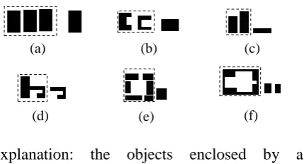
Fig.1 Objects on maps are viewed as a group in light of the Gestalt
principles: (a)proximity; (b)similarity; (c)similar direction;
(d)connectedness; (e)closed tendency; and (f)same region.
(b) (c)(d) (e) (f)
Explanation: the objects enclosed by a
dash-lined rectangle are viewed as a group.
Fig. 1. Objects on maps are viewed as a group in light of the gestalt principles: (a) proximity; (b) similarity; (c) similar direc-tion; (d) connectedness; (e) closed tendency; and (f) same region.
a tendency to be viewed as a group (Fig. 1). Four cate-gories of object groups can be differentiated according to the geometric ingredients of the single objects: point, linear, areal/polygonal, and complex object groups. Figure 2 shows a number of pairs of object groups. Thus, it is of great impor-tance to find methods to obtain direction relations between object groups.
Because none of the models for computing direction re-lations between object groups has been proposed, this paper will focus on filling this gap. After the introduction (Sect. 1), existing models for computing direction relations will be dis-cussed (Sect. 2). Then the theoretical foundations of the new approach will be presented (Sect. 3), and a Voronoi-based model for computing directions between object groups will be proposed (Sect. 4). After that, a number of experiments will be shown to demonstrate the validity of the proposed approach (Sect. 5). Finally, some conclusions will be made (Sect. 6).
2 Analysis of existing models
To propose a model for computing direction relations be-tween object groups, it is pertinent to summarize and ana-lyze previously existing ones to show their advantages and disadvantages.
To facilitate the discussion in the following sections, it is designated that
1. Ais the reference object (or object group), andBis the target object (or object group);
2. Dir(A, B)is the qualitative description of direction re-lations fromAtoB;
3. D(A, B)is the quantitative description of direction re-lations fromAtoB; and
4. only extrinsic reference frame is employed for direction relations.
– The cone-based model (Peuquet and Zhan, 1987)
par-titions the 2-dimensional space around the centroid of the reference object into four direction regions corre-sponding to the four cardinal directions (i.e., N, E, S, W). The direction of the target object with respect to the reference object is determined by the target object’s presence in a direction partition for the reference object. If the target object coincides with the reference object, the direction between them is called “same”.
This model is developed primarily to detect whether a target object exists in a given direction or not. If the dis-tance between the two objects is much larger than their size, the model works well; otherwise a special method must be used to adjust the area of acceptance. If objects are overlapping, intertwined, or horseshoe-shaped, this model uses centroids to determine directions (Peuquet and Zhan, 1987), and the results are misleading some-times. In addition, if a target object is in multiple direc-tions, such as{N, NE, E}, this model does not provide a knowledge structure to represent multiple directions (Goyal, 2000).
– The 2-D projection model (Frank, 1992; Nabil et al.,
1995; Safar and Shahabi, 1999) represents spatial rela-tions between objects using MBRs (minimum bounding rectangles). Reasoning between projections of MBRs on the x andy axes is performed using 1-D interval relations. Using this method, one can characterize rela-tions between MBRs of objects uniquely. There are 13 possible relations on an axis (Allen, 1983; Nabil et al., 1995) in 1-D space; therefore, this model distinguishes 13×13=169 relations in 2-D space.
The 2-D projection model approximates objects by their MBRs; therefore, the spatial relation may not necessar-ily be the same as the relation between exact representa-tions of the objects, because the model can not capture the details of objects in direction descriptions (Goyal, 2000). So this model can be only used for the qualita-tive description of direction relations.
– The direction-relation matrix model (Goyal, 2000)
par-titions space around the MBR of the reference object into nine direction tilts: N, NE, E, SE, S, SW, W, NW, and O (same direction). A direction-relation matrix is constructed to record if a section of the target object falls into a specific tilt. Further, to improve the relia-bility of the model, a detailed direction-relation matrix capturing more details by recording the area ratio of the target object in each tilt is employed.
The direction-relation matrix model provides a knowl-edge structure to record multilevel directions. How-ever, it can not obtain D(A, B)/Dir(A, B) from
D(B, A)/Dir(B, A)and vice versa (Yan et al., 2006).
H. Yan et al.: An approach to computing direction relations between separated object groups 1593
28
1 2
Village B Village A
(a)
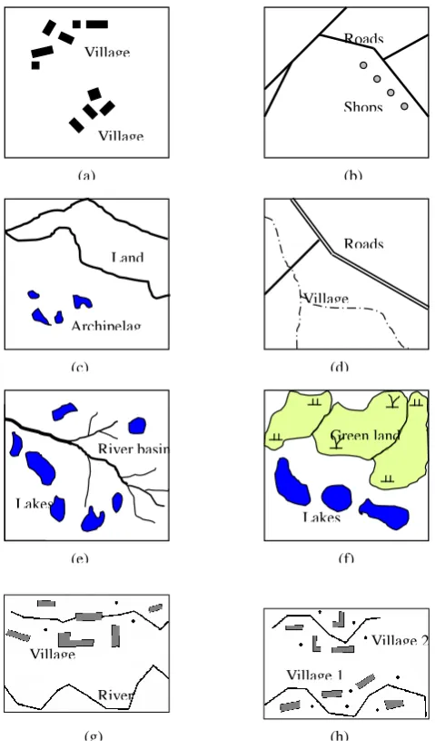
Fig.2 Examples of various pairs of object groups: (a) points-points; (b) points-lines; (c) points-polygons; (d) lines-lines; (e) lines-polygons; (f) polygons-polygons; (g) line-complex; and (h) complex-complex.
Archipelag o
Land
(c)
(b) Shops Roads
Village boundary
(d) Roads
River basin
(e) Lakes
(f) Lakes
Green land
Village
River
Village 2
Village 1
(g) (h)
Fig. 2. Examples of various pairs of object groups: (a) points– points; (b) points–lines; (c) points–polygons; (d) lines–lines; (e) lines–polygons; (f) polygons–polygons; (g) line–complex; and (h) complex–complex.
– The Voronoi-based model (Yan et al., 2006) uses
“di-rection group” because people describe di“di-rections be-tween two objects using multiple directions. A direction group consists of multiple directions, and each direction includes two components: the azimuths of the normals of direction Voronoi edges between two objects and the corresponding weights of the azimuths (Fig. 3). The Voronoi-based model can describe direction relations quantitatively and qualitatively, and can obtainD(B, A)by
D(A, B). Direction relations are recorded in 2-dimensional tables.
The above four models may be compared using the fol-lowing five criteria (Goyal, 2000; Yan et al., 2006).
29
1
2
3
4
5
6
7
8
9
10
11
12
13
14
15
Fig.3 Principle of the Voronoi-based model
used to describe direction relations between
single objects.
B
Voronoi
edges
A
Fig. 3. Principle of the Voronoi-based model used to describe direc-tion reladirec-tions between single objects.
1. simplicity: computation of the direction relations be-tween arbitrary two objects is not time-consuming, and the model is easy to be understood;
2. inversion: Dir(B, A)/D(B, A) can be obtained by Dir(A, B)/D(A, B);
3. correctness: results obtained are consistent with hu-man’s spatial cognition;
4. quantification: the model can give quantitative represen-tations of direction relations; and
5. qualification: the model can give qualitative representa-tions of direction relarepresenta-tions.
Table 1 shows the advantages and disadvantages of the above models. Obviously, none of the existing models meets the five criteria. And, particularly, none of them can be used to compute direction relations between object groups.
3 Theoretical foundations of multi-directions
Direction relations between object groups need to be de-scribed using multiple directions in many cases. The ex-amples of multiple directions are very common in the ge-ographic space. Especially if two object groups are inter-twined, enclosed, or overlapping with each other, description of direction relations with multiple directions becomes un-avoidable.
3.1 Examples of multi-directions
– Example 1: UniRoad composed of three roads passes
through University A composed of many buildings (Fig. 4). The direction relations between the road and the university can not be simply described by a single cardinal direction.
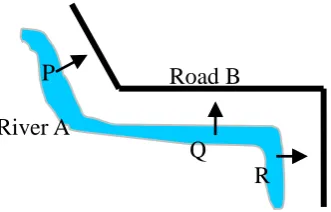
– Example 2: as a very common case, a road runs
approx-imately parallel with a river. In Fig. 5, a man may say “the road is to the northeast of the river” when he is at
P; and he may say “the road is to the north of the river”
Table 1. Comparison of the existing models.
Models Simplicity Inversion Correctness Qualification Quantification Cone-based model Yes Yes Not always Yes No
2-D projection model Yes Yes Not always Yes No Direction-relation matrix model Yes No Not always Yes Yes Voronoi-based model No Yes Yes Yes Yes
30
1
2
3
4
5
6
University A
University A
Un
iR
oa
d
UniRoad
Fig.4 Multi-directions are needed
when
two
object
groups
are
intertwined.
UniRoad
Fig. 4. Multi-directions are needed when two object groups are in-tertwined.
31
1
2
3
4
5
6
River A
Road B
Fig.5
Multi-directions
between
two
approximately parallel object groups.
R
Q
P
Fig. 5. Multi-directions between two approximately parallel object groups.
when he is atQ; however, if he walks toR, he may say: “the road is to the east of the river”. Nevertheless, all three answers are intuitively partial and unacceptable. To give a whole description, it is reasonable to combine the three answers.
– Example 3: in Fig. 6, villageA(a group of buildings)
is half-enclosed by riverR(a group of river branches). A single cardinal direction obtained by the cone-based model (e.g.,Ais at the south ofR) can not describe their direction relations clearly.
3.2 Cognitive explanation of multi-directions
From the point of view of perception, in any case, the follow-ing two principles remain unquestionable in direction judg-ments.
– Relations between the sum of the whole and its parts:
“the sum of the whole is greater than its parts” (Wertheimer, 1923; Clifford, 2002) is the idea behind
32
1
2
3
4
5
6
Fig.6 If an object group is half-enclosed by another group,
a single direction is not enough to describe their direction
relations.
Village V
River basin R
Fig. 6. If an object group is half-enclosed by another group, a single direction is not enough to describe their direction relations.
the principle of gestalt. It is the perception of a com-position as a whole. Human’s perception of the piece is based on their understanding of all the bits and pieces working in unison. People usually ignore the trivial of spatial objects but get the sketches of the whole be-fore they judge directions. Their judgments are based on the sketches but not on details. This process implies the idea of cartographic generalization. The generaliza-tion methods in direcgeneraliza-tion judgments are a little bit dif-ferent from those used in traditional map generalization (Weibel, 1996). The generalization scale depends on the size of the field formed by the two object groups. The larger the distance between the two groups, the larger the objects are generalized.
– Proximity: the principle of proximity or contiguity
states that nearby objects can be regarded as a group and more correlated (Alberto and Charles, 2011). Such examples exist almost everywhere in daily life. In Fig. 6, the three directions are obtained by the three pairs of proximal sections of the road and the river. Hence, “judg-ing directions by proximal sections” will be one of the most important principles in the new model.
3.3 Expression of multi-directions
In our daily life, when a man says “the hospital is to the east of the school”, he generally has an imaginary ray (here, ray is directly borrowed from its mathematical concept) in his brain, pointing from the hospital to the school indicat-ing the direction. Hence, it is a natural thought to express direction relations using such rays. If multi-directions exist between two object groups, a combination of multiple rays
H. Yan et al.: An approach to computing direction relations between separated object groups 1595
33
1
2 3 4 5 6
Fig.7 Normals of the Voronoi edges used to denote directions.
A
B
(a)
A L
(b)
Voronoi edge
Legend Ray
Fig. 7. Normals of the Voronoi edges used to denote directions.
can be utilized to denote their direction relations, each ray corresponding to a cardinal direction (Yan et al., 2006). For example, in Fig. 5, the directions from the river (A) to the road (B)may be expressed using a direction set Dir(A, B)= {NE, N, E}.
3.4 Reasonability of using Voronoi diagram to express
directions
It is difficult to get a certain ray pointing from one object to another; however, the normals of the ray (i.e., the Voronoi diagram of the two objects) can be obtained. Because a ray and its normal are perpendicular to each other, the ray can be obtained easily by its normals.
Figure 7 presents the Voronoi diagrams and the ray be-tween two point objects and bebe-tween a point object and a lin-ear object, respectively. Obviously, each of the rays (normal of the Voronoi diagram) denotes the direction relations.
4 A Voronoi-based model
To simplify the following discussion, the two object groups in Fig. 6 will be used as an example. Here, river basinR
is the reference object group; the villageV is the target ob-ject group. The eight-direction system (i.e., eight directions E, NE, N, NW, W, SW, S, and SE are discerned) will be em-ployed. Because both quantitative and qualitative direction relations are widely used in daily life, the proposed model will express direction relations in quantitative and qualitative ways.
4.1 Framework of the model
The new model for computing quantitative and direction re-lations consists of four procedures:
1. cartographic generalization of the two object groups; 2. construction of the Voronoi diagram;
3. computation of quantitative direction relations; and 4. construction of qualitative direction relations.
34
1
2 3 4 5
VillageV River basinR
(a)
Fig.8 Procedures of computing direction relations between two object groups: (a) generalized object groups; (b) triangulation of the object groups; (c) proximal sections of the object groups; and (d) Voronoi Diagram.
(b)
(c) (d)
Voronoi edges
Fig. 8. Procedures of computing direction relations between two object groups: (a) generalized object groups; (b) triangulation of the object groups; (c) proximal sections of the object groups; and (d) Voronoi diagram.
4.2 Cartographic generalization of the two object
groups
According to “the relations between the sum of the whole and its parts”, cartographic generalization is a first necessary step in human’s direction judgments. This procedure aims at simplifying object groups so that direction computation can be done in a simple way.
Suppose that the diameter of convex hull of the two object groups isd; Eq. (1) is used to simplify spatial objects.
S=d× [1−cos(ε/2)]/2 (1) whereS is the generalization scale of the objects (i.e., the details whose sizes are less thanSwill be simplified), andε
is an angle. It equals 90◦in the four-direction system and 45◦ in the eight-direction system.
The generalized result of Fig. 6 is shown in Fig. 8a, which can be used for computing direction relations in the eight-direction system.
4.3 Construction of the Voronoi diagram
It is well known that Delaunay triangulation is a useful and efficient tool in spatial adjacency/proximity analysis (Li et al., 2002); hence, it is used to get proximal sections of the two object groups. On the other hand, the Delaunay triangu-lar network and the Voronoi diagram are dual of each other (Arias et al., 2011); thus the Voronoi diagram of the two ob-ject groups can be easily obtained by their Delaunay trian-gular network. The Voronoi diagram can be obtained by fol-lowing steps.
First, construct a point set consisting of all of the vertices of the two object groups.
Second, construct the Delaunay triangular network (Fig. 8b) of the point set. If the three vertices of a triangle belong to one object group, it is called a “first-type triangle”; otherwise, it is called a “second-type triangle”.
1596 H. Yan et al.: An approach to computing direction relations between separated object groups
35
2
3
4
5
6
7
8
9
10
11
12
13
14
15
16
y
x
O
A
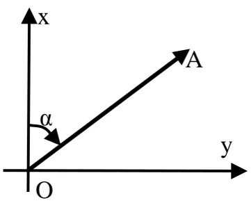
Fig.9 Definition of azimuth.
α
Fig. 9. Definition of azimuth.
Next, delete all of the first-type triangles. The remaining triangles compose the proximal area (Fig. 8c) of the two groups.
Finally, generate the Voronoi diagram (Fig. 8d) using the remaining triangles.
4.4 Computation of quantitative direction relations
The Voronoi diagram of two object groups generally consists ofn≥1 Voronoi edges (e.g., the Voronoi diagram in Fig. 8d has 15 edges); each Voronoi edge has a normal. Hence, a total ofnnormals can be obtained to denote the direction pointing from the reference object group to the target object group. In other words, there arendirections between the two object groups.
To describe direction relations quantitatively with then di-rections, the following three strategies are employed.
– A single direction can be described using the azimuth
of the normal of the Voronoi edge.
An azimuth of a ray is the angle measured clockwise from the positive end of the vertical axis of the Carte-sian coordinate system to the ray. Figure 9 shows the azimuth (α)of ray O–A.
– To differentiate the importance of each direction, each
direction is assigned a weight value, which is the per-centage of the length of each corresponding Voronoi edge.
Because each Voronoi edge corresponds to a single di-rection, the Voronoi diagram may be generalized using Eq. (1) as the criterion to simplify the final expression of the direction relations.
– To facilitate saving direction relations in databases, all
of the azimuths and their corresponding weights are listed in a 2-dimensional table.
The generalized Voronoi diagram in Fig. 8d is shown in Fig. 10. Its Voronoi edges are labeled. Table 2 presents the
Table 2. Quantitative description of direction relations fromRtoV
in Fig. 8.
Labeled Azimuth Weight edge (degree) (%)
1 1 11
2 82 20
3 133 26 4 205 16 5 237 27
36
1
2
3
4
5
6
Fig.10 Simplified and labeled
Voronoi edges with normals.
2 1 3
4 5
Normal Legend
Fig. 10. Simplified and labeled Voronoi edges with normals.
Table 3. Qualitative description of direction relations fromRtoV
in Fig. 8.
Labeled Direction Weight
edge (%)
1 N 11
2 E 20
3 SE 26
4, 5 SW 16+27=43
quantitative direction relations of the two object groups. Each direction consists of an angle and a weight value. This quan-titative result can be expressed asD(R, V )= {<1,11>, <
82,20>, <133,26>, <205,16>, <237,27>}.
4.5 Construction of qualitative direction relations
To qualify the quantitative direction relations, the following two steps are needed.
– Change the azimuths into qualitative directions.
In the eight-direction system, north means an azimuth in [337.5◦, 0◦]∪[0◦, 22.5◦]; northwest an azimuth in [22.5◦, 67.5◦]; east an azimuth in [67.5◦, 112.5◦]; south-east an azimuth in [112.5◦, 157.5◦]; south an azimuth in [157.5◦, 202.5◦]; southwest an azimuth in [202.5◦, 247.5◦]; west an azimuth in [247.5◦, 292.5◦]; northwest an azimuth in [292.5◦, 337.5◦].
– Combine the same cardinal directions, and add up their
corresponding weights.
Table 3 shows the qualitative description of direction re-lations fromR toV in Fig. 8. The directions of edge 4 and
H. Yan et al.: An approach to computing direction relations between separated object groups 1597
37
1 2
Fig.11 Examples of pairs of object groups used in the experiment: (a) point
point group; (b) line
point group; (c) polygon
point group; (d) line
line
network; (e) line
linear arranged polygon group; (f) polygon group
line
network; (g) polygon cluster
linear arranged polygon group; (h) polygon
complex group with polygons, lines and points.
(d) (e) (f)
(g) (h)
(a) (b) (c)
Legend:
Voronoi edge Q
P
Fig. 11. Examples of pairs of object groups used in the experiment: (A) point→point group; (b) line→point group; (c) polygon→point group; (d) line→line network; (e) line→linear arranged polygon group; (f) polygon group→line network; (g) polygon cluster→linear arranged polygon group; (h) polygon→complex group with polygons, lines and points.
Table 4. Qualitative direction relations of the pairs of object groups (the percentages are the weights of the directions).
Pair of groups N % NW % W % SW % S % SE % E % NE %
Fig. 11a 73.67 11.48 14.85
Fig. 11b 26.82 49.05 2.75 21.38 Fig. 11c 19.34 10.90 13.41 11.10 19.82 12.24 5.10 8.09 Fig. 11d 50.07 49.93
Fig. 11e 5.03 13.82 18.54 21.40 1.58 21.87 17.75 Fig. 11f 34.44 5.81 33.80 20.69 5.26 Fig. 11g 16.17 5.66 1.78 14.83 24.28 2.23 17.95 17.10 Fig. 11h 12.94 5.74 4.67 8.15 18.14 13.93 19.58 16.85
edge 5 are the same (SW); hence, they are combined and their weights are added up. This result can be Dir(R, V )= {<N,11>, <E,20>, <SE,26>, <SE,43>}. The quali-tative description of direction relations in Fig. 8 is as follows: 11 % ofV is to the north ofR, 20 % ofV to the east ofR, 26 % ofV to the southeast ofR, and 43 % ofV to the south-west ofR.
5 Experiments and discussions
Whether the proposed approach is correct and valid should be tested by psychological experiments, because judgments of directions are rooted in human’s spatial cognition (Egenhofer
and Shariff, 1998; Gayal, 2000). For this purpose, the direc-tion reladirec-tions of 40 pairs of object groups were computed using a C# program implemented by the authors. They were drawn in a table and distributed to 33 testees (all testees are graduates of Lanzhou Jiaotong University, China). The nat-ural language description of direction relations was attached to each pair of object groups. The testees were required to answer if they “totally agree”, “agree”, are “unsure”, or “do not agree” with each answer.
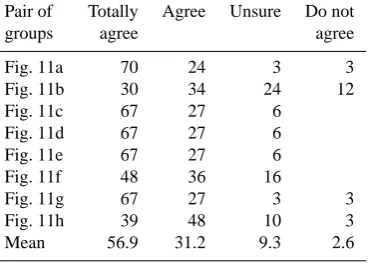
Figure 11 and Table 4 give eight typical examples of our experiment. The result of the psychological test is listed in Table 5. Some insights can be gained from the experiments.
Table 5. Statistical results of the psychological test (%).
Pair of Totally Agree Unsure Do not groups agree agree Fig. 11a 70 24 3 3 Fig. 11b 30 34 24 12 Fig. 11c 67 27 6
Fig. 11d 67 27 6 Fig. 11e 67 27 6 Fig. 11f 48 36 16
Fig. 11g 67 27 3 3 Fig. 11h 39 48 10 3 Mean 56.9 31.2 9.3 2.6
First, Dir(B, A) can be obtained from Dir(A, B) by the proposed approach. Taking Fig. 11a as an ex-ample, a simple inversion of the three cardinal di-rections in Dir(Q, P )= {<N,73.67>, <NW,11.48>, <
NE,14.85>} can generate Dir(P , Q)= {<S,73.67>, <
SE,11.48>, <SW,14.85>}.
Second, the mean of the confidence values from the test is 88.1 % (including “totally agree” and “agree”); the least is 64 %; the greatest is 94 %. Hence, this approach is acceptable and valid from the point of view of spatial cognition.
Third, the proposed approach can be used to compute di-rection relations both between single objects and between ob-ject groups (Fig. 11).
Fourth, the results obtained by the approach are both quan-titative (Table 4) and qualitative (Table 5). Moreover, the re-sults are saved in 2-dimensional tables, facilitating the con-struction of databases for direction relations.
And finally, if two object groups are intersected, con-tained and/or covered with each other (i.e., they have com-mon parts), the approach can not work well and needs to be improved.
6 Conclusions
This paper proposed an approach to computing direc-tion reladirec-tions between two separated object groups in 2-dimensional space. The approach is supported by two prin-ciples in gestalt theory. One is the principle of “the sum of the whole and its parts”, and the other one is the principle of proximity. Its validity and soundness has been proved by psychological experiments. The main advantages of this ap-proach can be summarized as follows: (1) it can compute direction relations between object groups, which the other models can not; (2) it can obtain Dir(A, B)from Dir(B, A)
without complex computation; (3) initial quantitative direc-tion reladirec-tions can be transformed into qualitative ones eas-ily; and (4) quantitative and qualitative direction relations can be recorded in 2-dimensional tables, which is useful in spa-tial database construction and spaspa-tial reasoning. Our further
research will focus on improving this approach so that it can be used to process topologically intersected and/or contained object groups.
Acknowledgements. The work described in this paper is
par-tially funded by the NSERC, Canada, parpar-tially funded by the National Support Plan in Science and Technology, China (No. 2013BAB05B01), and partially funded by the Natural Science Foundation Committee, China (No. 41371435).
Edited by: H. Weller
References
Abdelmoty, A. I. and Williams, M. H.: Approaches to the represen-tation of qualitative spatial relations for geographic databases, Geodesy, 40, 204–216, 1994.
Alberto, G. and Charles, S.: To what extent do Gestalt grouping principles influence tactile perception?, Psychol. Bull., 137, 538– 561, 2011.
Allen, J.: Maintaining Knowledge about Temporal Intervals, Com-munications of the ACM, 26, 832–843, 1983.
Arias, J. S., Szumik, C. A., and Goloboff, P. A.: Spatial analysis of vicariance: a method for using direct geographical information in historical biogeography, Cladistics, 27, 617–628, 2011. Bansal, V. K.: Application of geographic information systems in
construction safety planning, Int. J. Project Manage., 29, 66–77, 2011.
Cicerone, S. and De Felice, P.: Cardinal directions between spatial objects: the pairwise-consistency problem, Information Sci., 164, 165–188, 2004.
Clementini, E., Felice, P., and Hern´andez, D.: Qualitative represen-tation of positional information, Artificial Intelligence, 95, 317– 356, 1997.
Clifford, N. J.: The future of geography: when the whole is less than the sum of its parts, Geoforum, 33, 431–436, 2002.
Egenhofer, M. and Franzosa, R.: Point-set topological spatial rela-tions, Int. J. Geogr. Inf. Sys., 5, 161–174, 1991.
Egenhofer, M. and Shariff, R.: Metric details for natural-language spatial relations, ACM Trans. Inf. Syst., 16, 295–321, 1998. Frank, A. U.: Qualitative spatial reasoning about distances and
di-rections in geographic space, J. Visual Languages Comput., 3, 343–371, 1992.
Frank, A. U.: Qualitative spatial reasoning: cardinal directions as an example, Int. J. Geogr. Inf. Sys., 10, 269–290, 1996.
Goyal, R. K.: Similarity assessment for cardinal directions between extended spatial objects, PHD Thesis, The University of Maine, USA, 167 pp., 2000.
Hudelot, C., Atif, J., and Bloch, I.: Fuzzy spatial relation ontology for image interpretation, Fuzzy Set Syst., 159, 1929–1951, 2008. Kim, B. and Um, K.: 2D+string: a spatial metadata to reason topo-logical and direction relations. Proceedings of the 11th Interna-tional Conference on Scientific and Statistical Database Manage-ment, Cleveland, Ohio, 112–122, 1999.
Kuo, M. H., Chen, L. C., and Liang, C. W.: Building and evaluating a location-based service recommendation system with a prefer-ence adjustment mechanism, Expert Systems with Applications, 36, 3543–3554, 2009.
H. Yan et al.: An approach to computing direction relations between separated object groups 1599
Li, Z., Zhao, R., and Chen, J.: A Voronoi-based spatial algebra for spatial relations, Progr. Natural Sci., 12, 43–51, 2002.
Ligozat, G.: Reasoning about cardinal directions, J. Visual Lan-guages Comput., 9, 23–44, 1998.
Liu, S. L. and Chen, X.: Measuring distance between spatial objects in 2D GIS, in: Proceedings of the 2nd International Symposium on Spatial Data Quality, edited by: Shi, W. Z., Goodchild, M. F., and Fisher, P. F., Hongkong, China, 51–60, 2003.
Mitra, D.: A class of star-algebras for point-based qualitative rea-soning in two dimension space, in: Proceedings of the FLAIRS-2002, edited by: Mitra, D., Pendacola Beach, Florida, USA, 2002.
Mossakowski, T.: Qualitative reasoning about relative direction of oriented points, Artificial Intelligence, 180/181, 34–45, 2012. Nabil, M., Shepherd, J., and Ngu, A. H. H.: 2D projection
inter-val relations: a symbolic representation of spatial relations, in: Advances in Spatial Databases – 4th International Symposium, Egenhofer, M. and Herring, J., Lecture Notes in Computer Sci-ence, 951, 292–309, 1995.
Palmer, S. E.: Common region: a new principle of perceptual group-ing, Cognitive Psychology, 24, 436–447, 1992.
Papadias, D. and Theodoridis, Y.: Spatial relations, minimum bounding rectangles, and spatial data structures, Int. J. Geogr. Inf. Sci., 11, 111–138, 1997.
Peuquet, D. and Zhan, C. X.: An algorithm to determine the direc-tional relation between arbitrarily-shaped polygons in the plane, Pattern Recognition, 20, 65–74, 1987.
Roy, A. J. and Stell, J. G.: Spatialrelations between indeterminate regions, Int. J. Approx. Reason., 27, 205–234, 2001.
Safar, M. and Shahabi, C.: 2D Topological and Direction Relations in the World of Minimum Bounding Circles, in: Proceedings of the 1999 International Database Engineering and Applications Symposium, Montreal, Canada, 239–247, 1999.
Schneider, M. and Behr, T.: Topological relationships between com-plex spatial objects, ACM Trans. Database Sys., 31, 39–81, 2006. Sharma, J.: Integrated spatial reasoning in geographic information systems: combining topology and direction, PHD Thesis, Uni-versity of Maine, USA, 164 pp., 1996.
Shekhar, S. and Liu, X.: Direction as a spatial object: a summary of results, The 6th International Symposium on Advances in Geo-graphic Information Systems, Washingtong, USA, 69–75, 1998. Weibel, R.: A typology of constraints to line simplification, in: Ad-vances on GIS II, edited by: Kraak, M. J. and Molenaar, M., Tay-lor & Francis, London, 9A.1–9A.14, 1996.
Wertheimer, M.: Law of organization in perceptual forms, in: A Source Book of Gestalt Psychology, edited by: Ellis, W. D., Kegan Paul, Trench, Trubner, 71–88, 1923.
Wolter, D. and Lee, J. H.: Qualitative reasoning with directional relations, Artificial Intelligence, 174, 1498–1507, 2010. Yan, H.: Fundamental theories of spatial similarity relations in
multi-scale map spaces, Chinese Geogr. Sci., 20, 18–22, 2010. Yan, H., Chu, Y., Li, Z., and Guo, R.: A quantitative direction
de-scription model based on direction groups, Geoinformatica, 10, 177–196, 2006.
Yan, H., Weibel, R., and Yang, B.: A multi-parameter approach to automated building grouping and generalization, Geoinformat-ica, 12, 73–89, 2008.
Zimmermann, K. and Freksa, C.: Qualitative spatial reasoning using orientation, distance, and path knowledge, Appl. Intell., 6, 49– 58, 1996.