Structured Approach for Designing 4:2 Compressor
Hima Kantamneni, Mahmoud
Jawharji, and Damu RadhakrishnanDepartment of Electrical and Computer Engineering Division of Engineering Programs
State University of New York, New Paltz, NY 12561
[email protected], [email protected], [email protected]
Abstract —4:2 compressors play a large role in the design of arithmetic units, especially in the case of multipliers. In this study we compare different implementations of 4:2 compressors in terms of their power, delay, power delay product and the number of transistors used. A total of 36 different implementations are compared and simulated using LTSPICE, and the power consumption was found to vary from 0.12µw to 0.38µw, and the power-delay product from 0.12fJ to 0.30fJ at 0.6V using 45nm BICMOS technology. The transistor counts vary from 30 to 38 for different implementations of the 4:2 compressor.
Keyword —4:2 compressor, XOR gate, multiplexer, power, power delay product.
Introduction
Power reduction is one of the major challenges facing todays VLSI designers. With every new generation, the circuit complexity and processing speed increases. The frequency is reaching a top limit and is settling down in the 4-5GHz range. This is due to the high cost of heat removal from these chips. Hence, designers are always looking for ways to minimize power consumption in their designs.
In this paper we present various designs of a popular device called 4:2 compressor [1]. The 4:2 compressor merits significance because of its use in hardware multipliers and digital signal processing units such as Fast Fourier Transform (FFT). Hardware multipliers predominantly use 4:2 compressors in their partial product reduction stage because of their structured layout compared to normal full adder cells. Many designs for 4:2 compressors exist in the literature focusing on power reduction [2-9]. Our focus here is to design individual submodules of the 4:2 compressor in many ways and making different designs by combining these submodules in various ways. The different designs are then sorted out in terms of their power, delay and power delay product.
4:2 Compressor
A 4:2 compressor consists of five inputs and three outputs and can be implemented with two stages of full-adders (FA) connected one after the other as shown in Figure 1. Usually the sum output of a full adder is implemented by cascading two XOR gates. If we use a similar implementation for the full adders used in Figure 1, then the total delay for the sum output (S) of the 4:2 compressor will be 4 XOR delays. Various approaches have
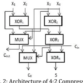
been proposed in literature to improve their speed. A novel design of a 4:2 compressor based on a modified set of equations for the sum and carry outputs of the compressor is shown in Figure 2 [2]. The output equations are:
Fig. 1. 4:2 Compressor Composed of Two FAs
Fig. 2: Architecture of 4:2 Compressor
358
The inverters at the input have the maximum switching activity compared to all other nodes in the circuit and hence the power dissipation of this circuit is increased. Modified multiplexer based designs for 4:2 compressors are presented in [5]. The XOR gates were replaced by multiplexers to minimize delay in the critical path. Multiplexers in the internal paths were implemented in the transmission gate style. The delay, power and area were reduced due to the combined XOR-XNOR module and multiplexers.
A number of low power 4:2 compressors are presented in [6]-[8]. The designs in [8] are driven by input signals without using any direct path to supply voltages, and result in lower short circuit power. A number of high speed, low power 3:2, 4:2 and 5:2 compressors capable of operating at ultra-low voltages are presented in [9]. 4:2 compressor designs in the cascaded full adder style by using optimized full adders are presented in [10], [11] and are shown to have 9% less latency and 16% reduction in power delay product (PDP) compared to earlier designs. In [12] the conventional 4:2 compressors were modified to merge with the partial product generation block of an n×n-bit multiplier, while eliminating n2 inverters. The
proposed compressors were reported to provide up to 20% energy reduction in 65nm CMOS technology.
A current mode fully differential 4:2 compressor in 65-nm CMOS technology is presented in [13], [14]. In [13] they claimed area reduction and speed improvement up to 45% compared to other high speed conventional compressor circuits, while maintaining lower PDP of 3.26fJ at 1.2V.
New Design of 4:2 Compressor
For convenience, the XORs in Figure 2 are numbered as XOR1, XOR2, XOR3 and XOR4. Three different designs for
XOR1 and XOR2 are shown in Figure 3 [15], [16]. All three
designs generate both XOR (H) and XNOR (HP) outputs.
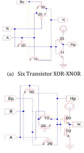
The transistor counts in these designs vary from 6 to 10. Fig. 3(a) uses a six transistor XOR-XNOR design. Figures 3(b) and 3(c) use explicit inverters for generating the XNOR output. Hence the XNOR output exhibits extra delay compared to the XOR output. Two designs for XOR3
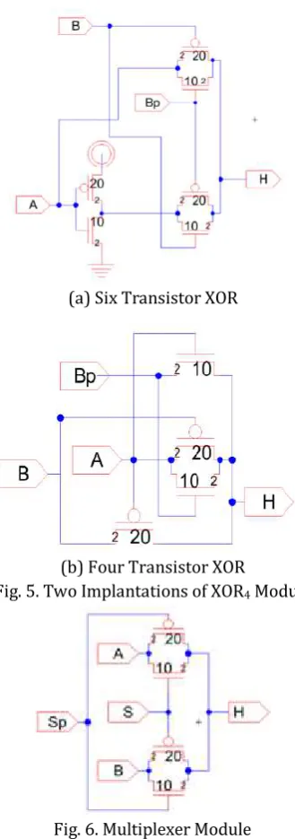
module are shown in Fig. 4. This module receives the inputs in both normal and complementary form, and hence the number of transistors used in their implementation is less than that used in XOR1 and XOR2.
Similarly, two designs of XOR4 module are shown in Fig. 5.
Fig 5(a) uses six transistors and Fig 5(b) uses four transistors. The design of multiplexer uses two transmission gates and is shown in Fig. 6.
(a) Six Transistor XOR-XNOR
(b) Ten Transistor XOR-XNOR
(c) Nine Transistor XOR-XNOR Fig. 3. XOR1 and XOR2 Modules
By combining the individual designs for the XOR gates at the different levels a total of 36 designs are possible for the 4:2 compressors.
(a) Six Transistor XOR-XNOR
(b) Six Transistor XOR-XNOR Fig. 4. Two Implementations of XOR3 Module
The designs (a), (b) and (c) are referred as A, B and C respectively later in this paper. Each 4:2 compressor is given a unique four letter label by combining the designs for the four XOR modules. For example, design ACAB refers to design A of XOR1, design C of XOR2, design A of
XOR3 and design of B of XOR4. The 2 to 1 multiplexer
359
Simulation Results
LTSPICE was used for simulation using 45nm BSIM4 bulk CMOS model [17]. All PMOS transistors were sized at 450nm and NMOS transistors at 225nm. Three different supply voltages were used: 1.2V, 0.8V and 0.6V. Simulations were carried out individually for each XOR gate module. Simulation results are tabulated in Table 1. The average power for design 3(a) at 0.6V is left blank in Table 1, since the output waveform for the 6 transistor XOR-XNOR gate was not showing good logic values. By comparing the power consumption of XOR modules in Figure 3(b) and 3(c), it may be noted that 3(b) consumes more power. This is because the input inverter feeds the gates of PMOS transistors of the transmission gate.
(a) Six Transistor XOR
(b) Four Transistor XOR
Fig. 5. Two Implantations of XOR4 Module
Fig. 6. Multiplexer Module
These PMOS transistors are double the size of NMOS transistors used in the transmission gate, and hence exhibits larger capacitive load on the inverter. The same is true for the designs in Figure 4(b) and Figure 5(a). The
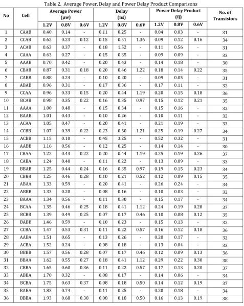
average power, delay and power-delay product for the different 4:2 compressor designs are tabulated in Table 2. They are arranged in ascending order of power. They vary
from 0.12μW to 0.38μW, and 0.12fJ to 0.30fJ at 0.6V. The
designs using the 6 transistor XOR-XNOR gates were not simulated at 0.6V and they are left blank in Table 2. The transistor counts used in each design are also shown in Table 2 (in index).
Table 1. Power Consumption of XOR Modules
Conclusion
A comparative study of 4:2 compressors is done in this paper. The 4:2 compressor is divided into four modules. For each module different designs are presented. Based on the division, 36 different designs are shown. They were all designed using 45nm BICMOS technology. Simulations were carried out using LTSPICE at three different supply voltages of 0.6V, 0.8V and 1.2V. At 0.6V, the six transistor XOR-XNOR gate designs used in XOR1 and XOR2 were not
producing good output waveforms and hence the power consumption using these gates were not calculated. They are left blank in Table 2. The power and power-delay product varied from 0.12μW to 0.38μW, and 0.12fJ to 0.30fJ respectively at 0.6V. The transistor count varies from 30 to 38 for different implementations.
References
[1]. A. Weinberger, “4-2 carry-save adder module,” IBM
Tech. Discl. Bulletin, vol. 23, Jan. 1981.
[2]. D. Ghosh, S.K. Nandy and K. Parthasarathy, "TWTXBB: A Low Latency, High Throughput Multiplier Architecture Using a New 4-2 Compressor," 7th Intl. Conf. on VLSI Design, Calcutta, India, pp. 77-82, Jan. 1994.
[3]. Y. Kanie, Y. Kubota, S. Toyoyama, Y. Iwase and S. Tsuchimoto, " 4-2 Compressor with Complementary Pass-Transistor Logic," IEICE Trans. Electron., vol. E77-C, no. 4, pp. 647-649, April 1994.
[4]. N. Ohkubo, M. Suzuki, T. Shinbo, T. Yamanaka, A.
Shimizu, K. Sasaki and Y. Nakagome, “A 4.4-ns CMOS 54X54-b Multiplier Using Pass-transistor Multiplier,”
Proc. IEEE Custom Integrated Circuits Conf., pp. 26.4.1-26.4.4, 1994.
[5]. J. Tonfat and R. Reis, “Low power 3–2 and 4–2 adder
compressors implemented using ASTRAN,” 2012 IEEE
360
March 2012.
[6]. C. H. Chang, J. Gu, and M. Zhang, “Ultra low-voltage low-power CMOS 4-2 and 5-2 compressors for fast arithmetic circuits,” IEEE Trans. Circuits and Syst., vol.
51, issue 10, pp. 1985-1997, Oct. 2004.
[7]. K. Prasad and K.K. Parhi, “Low-power 4-2 and 5-2
compressors,” Thirty-Fifth Asilomar Conference on
Signals, Systems and Computers, vol. 1, pp. 129-133, Pacific Grove, CA, USA, Nov. 2001.
[8]. P. D. Gopineedi, H. Thapliyal, M. B. Srinivas and H.
Arabnia, “Novel and Efficient 4:2 and 5:2 Compressors
with Minimum Number of Transistors Designed for
Low-Power Operations,” Proceedings of the 2006
International Conference on Embedded Systems & Applications, Las Vegas, Nevada, USA, ESA 2006: pp. 160-168, June 2006.
[9]. S. Veeramachaneni, et. al., “Novel Architectures for
High-Speed and Low-Power 3-2, 4-2 and 5-2
Compressors,” 20th International Conference on VLSI
Design, pp. 324-329, Jan. 2007.
[10].A Pishvaie, G. Jaberipur and A. Jahanian, “High Performance CMOS (4; 2) compressors,” International Journal of Electronics, vol. 101, issue 11, pp. 1511-1525, Jan. 2014.
[11].A Pishvaie, G. Jaberipur and A. Jahanian, “Improved CMOS (4; 2) compressor designs for parallel
multipliers,” Computers & Electrical Engineering, vol. 38, issue 6, pp. 1703-1716, Nov. 2012.
[12].D. Baran, M. Aktan and V.G. Oklobdzija, “Energy
efficient implementation of parallel CMOS multipliers
with improved compressors,” 16th ACM/IEEE
international symposium on low-power electronics and design, pp. 147–152, Austin, TX, USA, Aug. 2010. [13].P. Aliparast, Z.D. Koozehkanani, A.M. Khiavi,
G. Karimian and H.B. Bahar, “A very high-speed CMOS 4-2 compressor using fully differential current-mode
circuit techniques,” Analog Integrated Circuits and
Signal Processing, vol. 66, Issue 2, pp. 235–243, Feb. 2011.
[14].P. Aliparast, Z.D. Koozehkanani and F. Nazari, “An Ultra
High Speed Digital 4-2 Compressor in 65-nm CMOS,”
International Journal of Computer Theory and Engineering, vol. 5, no. 4, pp. 593-597, Aug. 2013. [15].A. M. Shams and M.A. Bayoumi, "A Structured Approach
for Designing Low Power Adders," Proc. 31st ASILOMAR Conf. on Signals, Systems and Computers, vol. 1, pp. 751-761, 1998.
[16].D. Radhakrishnan, "Low Voltage CMOS Full Adder," IEE Proc-Circuits, Devices Syst., vol. 148, no. 1, pp. 19-24, Feb. 2001.
[17].http://ptm.asu.edu
Author’s Profile
Hima Kantamneni - Hima Kantamneni completed her MS degree in Electrical Engineering from the State University of New York, New Paltz, New York in 2017. Her research interests are in Digital IC Design, especially in the area of Low Power High Speed Designs. She is an active student member of IEEE.
Mahmoud Jawharji - Mahmoud Jawharji finished his BS in Com-puter Engineering and MS in Electrical Engineering from the State University of New York, New Paltz, New York in 2017, and then moved back to Saudi Arabia. His MS thesis was on
“Low Power Partial Product Reduction Stage for Booth Multipliers”. During his last year of his MS
program, Mahmoud also worked as a teacher assistant for the Department of Engineering for a year. His passion is to continue research and pursue an academic career.
Index
Table 2. Average Power, Delay and Power Delay Product Comparisons
No Cell Average Power (µw) Delay (ns) Power Delay Product (fj) No. of
Transistors
1.2V 0.8V 0.6V 1.2V 0.8V 0.6V 1.2V 0.8V 0.6V