Design, Development and Kinematic Analysis of Robotic Arm
Manipulators
1
A.Ramanath, B.Jithendra Kumar
21
M.Tech student, Dept. of Mechanical Engg, Nova College of Engineering & Technology 2Associate Professor, Dept. of Mechanical Engg, Nova College of Engineering & Technology
1.
INTRODUCTION
A robotic arm is a type of mechanical arm, usually programmable, with similar functions to a human arm the arm may be the sum total of the mechanism or may be part of a more multifarious robot. The links of such a manipulator are connected by joints allowing either rotational motion (such as in an articulated robot) or translational (linear) displacement [1]. The links of the manipulator can be considered to form a kinematic chain. The boundary of the kinematic chain of the manipulator is called the end effectors’ and it is analogous to the human hand. The common industrial manipulator is often referred to as a robot arm, with links and joints described in similar terms. Manipulators which emulate the characteristics of a human arm are called articulated arms. All their joints are rotary (or revolute). Representative articulated manipulators are the ASEA robot. The motion of articulated robot arms differs from the motion of the human arm. While robot joints have fewer degrees of freedom, they can move through greater angles. For example, the elbow of an articulated robot can bend up or down whereas a person can only bend their elbow in one direction with respect to the straight arm position
2.0 LITERATURE REVIEW
Mehmet et.al studied the kinematics of manipulators is a central problem in the automatic control of robot manipulators. Theoretical background for the analysis of the 5 Dof Lynx-6 educational Robot Arm kinematics is presented in this paper. The kinematics problem is defined as the transformation from the Cartesian space to the joint space and vice versa. Anurag verma et.al concluded the kinematic analysis of a SCORBOT-ER Vplus robot arm which is used for doing successful robotic manipulation task in its workspace. The SCORBOT-ER Vplus is a 5-dof vertical articulated robot and all the joints are revolute. The kinematics problem is defined as the transformation from the Cartesian space to the joint space and vice versa. The Denavit-Harbenterg (D-H) model of representation is used to model robot links and joints in this study along with 4x4 homogeneous matrixes. SCORBOT-ER Vplus is a dependable and safe robotic system designed for laboratory and training applications. This versatile system allows students to gain theoretical and practical experience in robotics, automation and control systems[2]. The MATLAB 8.0 is used to solve this mathematical model for a set of joint
ABSTRACT:
Robot is a machine that collects the information about the milieu using some sensors and makes a decision robotically. People prefer it to use different field, such as industry, some dangerous jobs including radioactive effects. In this point, robots are regarded as a server. They can be managed easily and provides many advantages. Robot kinematics is the study of the motion (kinematics) of robots. In a kinematic analysis the position, velocity and acceleration of all the links are calculated without taking into consideration the forces that cause this motion. The correlation between motion, and the associated forces and torques is studied in robot dynamics. In this Paper, a robotic arm with 3 freedom degrees is designed and modeled using Solidworks. Kinematic analysis will be performed on the robotic arm manipulator to calculate position velocity and acceleration without considering the forces. Static analysis will also be performed to calculate the stresses by considering the forces.3
MODELLING
APPROACH
a. Introduction to Computer Aided Design
Computer Aided Design is an interactive process, where the exchange of information between the designer and the computer is made as simple and effective as possible. Computer aided design encompasses a wide variety of computer based methodologies and tools for a spectrum of engineering activities planning, analysis, detailing, drafting, construction, manufacturing, monitoring, management, process control and maintenance. CAD is more concerned with the use of computer-based tools to support the entire life cycle of engineering system.
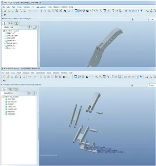
Figure 1 Assembly of manipulator parts
Figure 2 Individual manipulator parts
4.0 STATIC ANALYSIS OF ROBOTIC ARM
MATERIAL – ALUMINUM ALLOY
I. TABLE 1: LOADS AND FIXTURES FIGURE3VON-MISSES STRESSES
Fixture name Fixture Image Fixture Details
Fixed-1
Entities: 1 face(s)
Type: Fixed Geometry
Resultant Forces
Components X Y Z Resu
ltant
Reaction force(N) 9.59901e-6 1.03191e-6 0.000165 0.000166
Reaction
Moment(N.m) 0 0 0 0
Load name Load Image Load Details
Pressure-1
Entities: 2 face(s)
Type: Normal to selected face
Value: 19.5
Units: N/mm^2 (MPa)
Phase Angle: 0
Units: deg
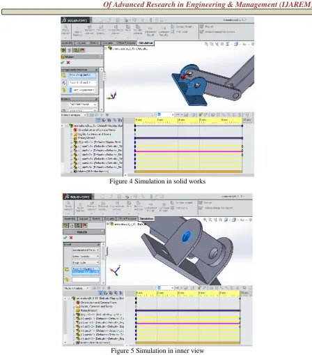
5.0 SIMULATION AND MOTION STUDIES
Figure 4 Simulation in solid works
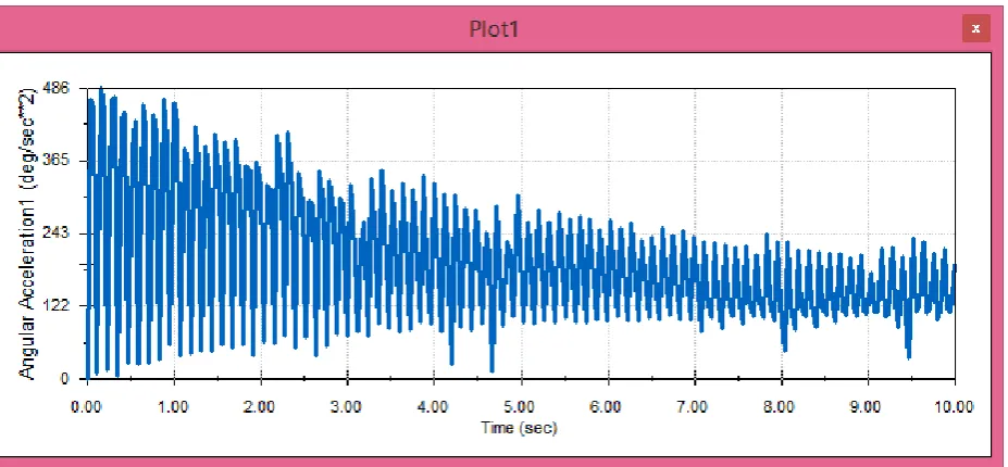
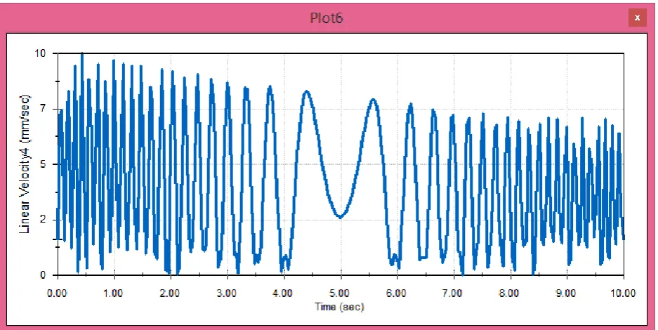
6.0 KINEMATIC ANALYSIS RESULTS
Table (2).motor speed - 1000rpm Linear velocity Vs time
Acceleration Vs time
Table (3) . Motor speed - 2000rpm linear velocity Vs time
Acceleration Vs time
Table (4) . Motor speed - 3000RPM Linear velocity Vs time
Acceleration Vs time
7.0 CONCLUSION
In this paper, a robotic arm with 3 freedom degrees is designed and modeled using Solid works. Static analysis is performed to calculate the stresses by considering the forces. The materials used are Steel and Aluminum alloy. By observing the results, the stress values are less than the strength of both the materials by applying load of 2000Kgs on the arm.
Kinematic analysis is performed on the robotic arm manipulator to calculate position velocity and acceleration without considering the forces. The analysis is performed at motor speed of 1000rpm, 2000rpm and 3000rpm. By observing the kinematic analysis results, by increasing the motor rpm linear velocity and acceleration is increased with respect to time.
The kinematic analysis results for tow materials alloy steel and alloy aluminum, we obtained the results
FOR ALLOY STEEL
Von miss stress = 37.9092 N/mm^2 Resultant displacement = 0.00170663mm equivalent strain = 0.000130404
FOR ALLOY ALUMINUM
Von miss stress = 38.0743 N/mm^2 Resultant displacement = 0.00530118mm Equivalent strain = 0.00041295
From the above calculations for these metals to see which materials best in terms of safety factor, that the metal steel alloy is better than of metal aluminum alloy based on the safety factor for each metal
It was found that the metal first highest factor of the second metal equivalent to 11 times in terms of stress tolerance
REFERENCES
[1]. Stress Analysis For Robotic Arm V2analisa Tecasan Bagi Lengan Robotikv2
[2]. Anwar A. R1, Fikri A2, K Salleh M. S 2, M Arif Hamzah1, Azraf Azman1, Rosli Darmawan1, Fadil Ismail1, M Nor Atan1, M Rizal Ml1
[3]. Software Development for the Kinematic Analysis of a Lynx 6 Robot Arm by Baki Koyuncu, and Mehmet Güzel.
[4]. End-effector Position Analysis of SCORBOT-ER Vplus Robot by Dr. AnuragVerma and Vivek A. Deshpande
[5]. The development of six D.O.F. robot arm for intelligent robot by Jie-Tong Zou
[6]. Kinematic Analysis and Simulation of 6Dof KukaKr5 Robot For Welding Application by K.Kishore Kumar, Dr.A.Srinath
[7]. End-Effector Position Analysis Using Forward Kinematics for 5 DOF Pravak Robot Arm by Jolly Shah, S.S.Rattan, B.C.Nakra
[8]. Design and Implementation of Robot Arm Control Using LabView and ARM Controller by Mr. C. Chandra Mouli, Ms. P. Jyothi
[9]. Kinematic modelling and analysis of 5 DOF robotic arm by Vivek Deshpande& P M George
[10].A Geometric Approach for Robotic Arm Kinematics with Hardware Design, Electrical Design, and Implementation by Kurt E. Clothier and Ying Shang
[11].Kinematic Analysis Using Neuro-fuzzy Intelligent Technique for Robotic Manipulator by Shiv Manjaree, Vijyant Agarwal and B.C. Nakra
[12].A new formulation method for solving kinematic problems of multiarm robot systems using quaternion algebra in the screw theory framework by Emre SARIYILDIZ, Hakan TEMELTAS