Volume 3, Issue 4, April 2014
Page 248
ABSTRACT
This paper deals with the application based comparative study of two designs of single phase reactive shear coaxial jets on the basis of flame length. The flow is characterised by high velocity outer jet and low velocity inner jet. Velocity of inner jet was kept constant and that of outer jet was varied, and a graph was plotted between the flame length and velocity ratios. A new design of shear coaxial jet was investigated which was bearing perforations on the orifice. Trends of flame length were observed and at better of the designs was evaluated in the end on the basis of demands of the applications. Three major applications like fuel injectors, industrial flame thrower and fire safety are discussed.
Keywords: Shear coaxial jets, flame length, velocity ratio and orifice perforations.
1.
INTRODUCTION
Coaxial jets are referred to such an arrangement of impinging jets, in which two impinging jets share same impingement axis and same direction of mass efflux. They are used in many advanced applications like fuel injectors, industrial mixers, fire safety nozzles and turbojet engine exhaust. The aim of the study undertaken was to do a comparison between conventional core coaxial jet and perforated core coaxial jet (with sharp orifice) on the basis of flame length. Efficiency of the designs is purely application dependent. Section 5 discusses both the designs thoroughly on the basis of applications and tells superior of the two. As the paper deals in combustion, so the discussion is limited to the mixing in coaxial jets only. Many investigations have been undertaken in order to improve the efficiency and mixing characterization of coaxial jets. Work undertaken by Schumaker M.A. (2009) [7] deals with the comprehensive investigation of mixing in reactive and non-reactive coaxial jets. The study used various fluid models of coaxial jets and checked their validation practically. Main aim was to make a database for rocket fuel injectors in order to get the most efficient design. Different diameter ratios of shear-shear coaxial jets were used. Mixing studies in non-reactive fluids have also been performed using concentration gradient as marking factor. Villermaux E. et al (2000) [11] studied the stoichiometric mixing length in non-reacting coaxial jet using fluorescence dye as seeding agent. Study revealed that the dilution length Ld is sole function of threshold concentration Cs. Using shear instability argument they argued that:
(1)
On combining the findings of Dahm et al (1992) [2] and Villermaux E. et al (2000) [11], stoichiometric mixing length can be written in terms of momentum ratio (for velocity ratios less than one), stoichiometric mixing fraction (f) and assuming constant concentration ratio and momentum ratio, as:
(2)
(3)
Where Ls is stoichiometric mixing length, M is momentum flux ratio, S is density ratio and R is velocity ratio.
Schumaker M.A. et al (2007) [8] have investigated the validation of equation (2) for velocity ratios ranging from 0 to 1, and different density ratios were considered for the study. The hypothesis revealed a good relation in lower regimes of velocity ratio and density ratio. At higher values, the relation does not hold good. Using momentum conservation theory, Schumaker M.A. et al (2012) [6] reavealed that density ratio and inverse velocity ratio increase when the inner jet is cold, and decreases when outer jet is cold. The study revealed that in a coaxial flow, the effective Reynolds number for the flow can be given by:
(4)
Implications of Perforations at the Inner Jet
Orifice on Flame Length in a Single phase
Reactive Shear Coaxial Jet
Sushank Sharma and Pankhuri Arora
Volume 3, Issue 4, April 2014
Page 249
For the proper comparison of various designs of coaxial jet, near field study is done in case of fuel injectors and far field study is done for industrial grade applications like conveyor heating, blast furnace and fire safety applications. Various configurations of coaxial jets such as shear or swirl coaxial jets are compared on important parameters like flame length, mixing contour and mixing length. Salgues et al [5] studied rocket combustion with a scaled model of rocket combustor for chamber pressure 4.14 MPa and flow rates of 0.118 kg/s for LOX and 0.039 kg/s for GCH4. Various diagnostic techniques such as OH-PLIF, OH* chemiluminescence, laser scattering and shadow graph were used for investigation. Various important parameters like flow structure, atomization process and combustion efficiency were studied. Study concluded on basis of the above stated parameters that swirl coaxial jet was more efficient as a fuel injector for rocket combustor as compared to shear coaxial jet. Ping J. et al (2013) [4] studied about the various important parameters which should be necessarily there in any coaxial jet for being a coaxial injector in a rocket combustor. Single phase reactive coaxial jet with fluids as GH2/GO2 was investigated numerically, the flow had temperature gradient. Temperature and pressure were taken from chamber through temperature and pressure sensors. Study was validated by comparing the plots of combustion length, average gas temperature on combustor wall and face plate. Concluded that shearing effect is the main influencing factor for combustion efficiency. Larger heat load is favourable for better combustion. The study left the areas of quantitative research in combustion performance and thermal protection in hot gases as scope for further studies. Segalini (2000) [9] studied the different designs of shear coaxial jet with conventional and sharp orifice ending. The study investigated the implications of various designs on flow stability and mixing. Instability and their reasons in different velocity regimes are provided, which state that the sharp wall orifice design gives stable flow and efficient flow mixing. Ditaranto M. et al [3] studied industrial application of coaxial jets i.e. industrial grade coaxial burners with oxygen enrichment. Gaseous methane and oxygen were used as working fluids. Study concluded that oxygen enrichment had great impact on the flame study which is linked to the development of the annular and core jet. It also pointed out that the flame puts out at point when the stoichiometric mixing fraction is reached on the centreline. Implications on pollutant emissions by enhancing mixing in coaxial jets was studied by Cozzi F. et al (2011) [1]. Effects of air staging were studied in a natural gas to air coaxial jet. Staging results registered a decrease in pollutant emission proving shear coaxial jets to be more efficient. Sreenivasan R. et al (2012) [10] studied the implications of coflowing air and partial premixing on LPG flames. Single phase fuel-air coaxial jet which used air and LPG as working fluids was investigated. Gas analyser was used in order to check the amount of soot and oxides of nitrogen. Results concluded that with minor increment in the flow of outer jet, blue region of flame increases and soot emission decreases, but soot inception increased initially. Increase in flow of outer air steeply decreases the amount of CO produced. It also found that dual stream configuration gives lower pollutant emission and provides higher flame stability.2.
EXPERIMENTAL SETUP
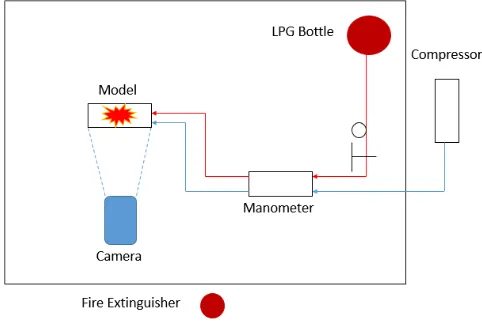
To undertake the experimental studies, an experimental setup was raised whose key components were LPG bottle, air compressor, differential manometer, flow control valve, CMOS camera and pressure hoses. Whole of the setup was kept in a dark room in order to obtain the required clarity of all the images and to nullify any unwanted visual aberrations. Figure 1 depicts the schematic of the experimental setup.
Figure 1: Schematic of the experimental Setup
Volume 3, Issue 4, April 2014
Page 250
Table 1: Design configuration of coaxial jetCore Type Inner Jet diameter (mm)
Outer Jet
diameter (mm)
Inner jet wall
thickness (mm)
Diameter ratio
(outer/inner)
Regular Core 4 12 1 3
Perforated Core 4 12 1 3
Dimensions of the block were 20X5X5cm, and the jets were made at a distance of seven centimetres from each other. The design was first made in CATIA V5 and then was fabricated. Outer jet was made by drilling a hole of 12mm up to 40mm depth and inlets of outer jet were made by drilling a through hole of 11mm on the opposite sides of the block.
Figure 2: CAD model of coaxial jet (left), actual fabricated model of coaxial jet (right)
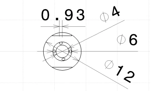
Figure 3: Sectional view of the fabricated coaxial jet
Circular core coaxial jet had normal conventional design, but the perforated core coaxial jet was bearing four symmetrical perforations of 1mm diameter over the orifice. A slant was also provided in order to ensure the sharp orifice. These small details changed the design of the jet keeping the other dimensions like diameter ratio as constant.
Volume 3, Issue 4, April 2014
Page 251
3.
RESEARCH METHODOLOGY
For calculating the velocity ratio, first of all the volumetric flow rate was calculated using the Hagen Poiseuille equation. This relation relates pressure across a cylindrical pipe and mass flow rate through it. It assumes that the flow as incompressible, Newtonian and is laminar through a pipe of constant circular cross section that is substantially longer than its diameter and there is no acceleration of fluid in the pipe. The relation can be represented as:
(5)
Where ΔP is pressure drop across the tapping points, L is the distance between the tapping points, Q is the volumetric flow rate of the fluid flowing in the pipeline, μ is the dynamic viscosity of the fluid and r is the radius of the pipe through which the fluid is flowing.
Flow rates of the both fluids i.e. compressed air and LPG were measured using differential u-tube manometer and hence the individual velocities of jets were calculated, which in turn gave the velocity ratio.
Flame was captured using Canon PowerShot SX50 HS CMOS camera. The camera was equipped with DIGIC 5 image processor and was capable of shooting at high frame rate in HD mode. For each case a video was shot and frame-by-frame flame lengths were recorded. At the end, the average of all the readings were taken which gave the flame length of that particular case. The average frame rate of the videos was 23 frames per second which gave a very in-depth view of the flame length variation per second. At the end a graph was plotted between the flame length and velocity ratio.
4.
RESULTS AND DISCUSSION
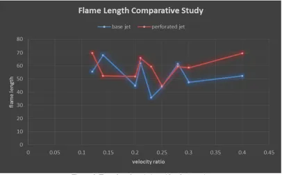
After the completion of the experimentation, the graph was plotted between flame length and the velocity ratio. For obtaining various velocity ratios, the velocity of core jet was kept constant and the outer jet velocity was increased gradually in systematic manner. Trends were plotted on the same plot for circular core coaxial jet and perforated core coaxial jet in order to clearly represent the variations between the two designs on the basis of flame length. Velocity ratios ranging from 0.12 to 0.4 were investigated, and both jets have different flame length at a given value of velocity ratio. Figure 4 depicts the trend of variation of flame length with varying velocity ratio. Blue coloured curve represents the trend of circular core coaxial jet (base jet) and orange coloured curve represents the trend observed in case of perforated core coaxial jet.
Figure 4: Flame length variation with velocity ratio
Volume 3, Issue 4, April 2014
Page 252
core coaxial jet, hence the flame became shorter. From velocity ratio 0.14 to 0.2, perforated core coaxial jet performed quite well and maintained a consistent flame length throughout this particular range, on the other hand circular core coaxial jet registered a constant decrease in flame length. Noticeably, in the range of 0.2 to 0.28 both jets exhibited the same trend. But, up to 0.25 flame length of perforated core coaxial jet was more than the circular core jet and from 0.25 to 0.28 flame length of both the models was approximately equal. Beyond 0.28 to 0.4, flame length in case of perforated core coaxial jet first registered a slight decrease and then a sudden increase, while in circular core coaxial jet there is an initial sharp decrease from 0.28 to 0.3 and then an increase from 0.28 to 0.4. Hence it can be concluded from the above discussion that for velocity ratios ranging from 0.18 to 0.25 and from 0.28 to 0.4, the flame length in case of sharp walled perforated core coaxial jet is more as compared to circular core coaxial jet. These increases in the flame length are actually a direct implication of the stability in the coaxial flow. The inference is actually supported by the study conducted by Segalini (2000) [9] which concluded that in a sharp orifice core coaxial jets the coaxial flow becomes stable for certain velocity ratios due delay in the formation of Von Karman vortices which are formed in far down stream as compared to the circular core coaxial jet. Also, it was observed that with the variation in flame length luminosity of the flame also changes. Flame starts changing the colour to bluer side indicating an increase in flame temperature. LPG flame temperature varies from a temperature of nine hundred degree Celsius to fifteen hundred degree Celsius varying its colour from yellow to blue. Bluer the flame, the hotter it is.Figure 5: Flame length for velocity ratio 0.4, 0.28 and 0.25 (perforated core coaxial jet)
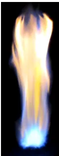
It is quite evident from the images that although the flame length is decreasing but also the flame is turning bluer and flame length is decreasing too. This signifies that at increased velocity ratios we have smaller and hotter flame which helps in good localised heating.
Figure 6: Flame at velocity ratio 0.25
5.
APPLICATIONS
This section reviews the major applications of coaxial jets such as fire safety nozzles, fuel injectors, blast furnaces or industrial flame throwers (for heating conveyors).
5.1.FIRE SAFETY
Volume 3, Issue 4, April 2014
Page 253
would prove better because they tend to destabilize the flame to greater extend in given range. So, conventional core circular coaxial jet is more efficient in case of fire safety.5.2. FUEL INJECTOR
One of the other key applications of coaxial jets is fuel injectors used in turbine engine application, rocket combustor and ramjet flame holders. Vital necessity of this application is that the flame obtained should be hot and of consistent length. Keeping these constraints in mind, for the velocity ratio regimes of 0.14 to 0.2 and from 0.28 to 0.4, the perforated core coaxial jets prove to be better in term of consistency and localised hot flames. This proves that this new design of reactive shear coaxial jet can be employed as fuel injector and flame holders after completing certain requirements necessary for coaxial injectors.
5.3. INDUSTRIAL FLAME THROWERS
For industrial flame thrower applications such as conveyor heaters and blast furnaces the key requirement is the long length of the flame. From figure 4, it is quite clear that for velocity ratio 0.14 and 0.28, conventional circular core coaxial jet provide longer flame as compared to perforated core coaxial jet. For these velocity ratios the circular core coaxial jets are efficient flame throwers. Perforated core coaxial jets can be utilized as better flame thrower nozzles in other cases of velocity ratio except 0.25 where both the designs have identical flame length.
REFERENCES
[1] Cozzi F. and Coghe A., “Effect of air staging on a coaxial swirled natural gas flame”, MCS7, Chia Laguna, Cagliari, Sardinia, Italy, September 2011.
[2] Dahm W.J.A., Frieler C.E. and Tryggvason G., “Vortex structure and dynamics in the near field of a coaxial jet”, Journal of Fluid Mechanics, Vol. 241, 1992, pp 371-402.
[3] Ditaranto M. and Hals J., “Flame length over a coaxial burner with oxygen enrichment”, Joint meeting of The Scandinavian-Nordic and Italian sections of the Combustion Institute, 7.2.1-7.2.4
[4] Ping J., Mao L. and Guo-Biano C., “Numerical and experimental study on shear coaxial injectors with hot hydrogen-rich gas/oxygen-hydrogen-rich gas and GH2/GO2”, Chin. Phys. B, Vol. 22, No. 4, 2013, pp 044701-01 - 044701-12.
[5] Salgues D., Mouis G., Lee S.Y., Kalitan D.M., Pal S. and Santoro R., “Shear and swirl coaxial injector studies of LOX/GCH4 Rocket combustion using Non-intrusive laser diagnostics”, AIAA, pp 1-14.
[6] Schumaker S.A. and Driscoll J.F., “Mixing properties of coaxial jets with large velocity ratios and large inverse density ratios”, Phys. Fluids 24, 055101 (2012), pp 055101-1 – 055101-21.
[7] Schumaker S.A., “An experimental investigation of reacting and non-reacting coaxial jet mixing in a Laboratory Rocket Engine”, (Doctorate thesis), University of Michigan, USA, 2009.
[8] Schumaker S.A. and Driscoll J.F., “Mixing lengths of coaxial jets in a rocket combustor configuration using Acetone
PLIF”, 43rd AIAA/ASME/SAE/ASEE Joint Propulsion Conference, AIAA 2007-5590, 2007, pp 1-14.
[9] Segalini A., “Experimental analysis of coaxial jets: instability, flow and mixing characterization”, (Master’s thesis), Universita di Bologna, 2010.
[10]Sreenivasan R. Koli S.K. and Raghavan V., “Experimental study of effect of coflow and partial premixing on Liquid
Petroleum Gas Flames”, ISRN Thermodynmics, Vol 2012, Article ID: 202715, 2012.
[11]Villermaux E. and Rehab H., “Mixing in coaxial jets”, Journal of Fluid Mechanics, Vol. 425, 2000, pp 161-185.
AUTHORS
Sushank Sharma has completed his Bachelor’s Degree from SRM University, Chennai, Tamil Nadu in field of Aerospace Engineering. His research interests includes areas for combustion, propulsion and experimental diagnostics in flames.