29
International Journal of Engineering and Management Research, Vol. 2, Issue-5, October 2012
ISSN No.: 2250-0758
Pages: 29-35
www.ijemr.net
Designing of Software Simulation Test bed for 3G Wireless
Communication System
H. Umadevi1, B.S Sudha2, Kavitha Devi C S3, Meenakshi L Rathod4, Akalpita L. Kulkarni5, K.S. Gurumurthy6
1,2,3,4
Department of Electronics & Communication, Dr Ambedkar Institute of Technology
5
Department of Electronics & Communication, University Visvesvaraya College of Engineering
1
[email protected], [email protected], [email protected], [email protected],
5
[email protected], [email protected]
Abstract
In this paper software is developed for wireless communication test bed which simulates a 3G Wireless Communication System using Wideband Code Division Multiple Access (CDMA) link. CDMA is a popular technology in cellular systems due to its superior capacity and performance. The designer of CDMA systems has a wide array of signal processing algorithms to choose from and a variety of operating environments to deal with. The test bed is a tool to evaluate these design options and trade-offs in different scenarios. The backbone of this system is a wireless WCDMA multiuser link built using Simulink and Matlab. We investigate the bit error rate at both uplink and downlink for different channel conditions. The software test bed developed can be an invaluable tool for learners and researchers for investigating the design and implementation of 3G Wireless Communication systems.
I.
INTRODUCTIONThe goal for the next generation of mobile communications system is to seamlessly provide a wide variety of communication services to anybody, anywhere, anytime. The intended service for next generation mobile phone users includes services like transmitting high speed data, video and multimedia traffic as well as voice signals [1- 2]. The technology needed to tackle the challenges to make these services available is popularly known as the Third Generation (3G) Cellular Systems. The first generation systems are represented by the analog mobile systems designed to carry the voice application traffic. Their subsequent digital counterparts are known as second generation cellular systems. Third generation Systems mark a significant leap, both in applications and capacity, from the current second generation standards. Whereas the current digital mobile phone systems are optimized for voice communications, 3G communicators are oriented towards multimedia message capability.
1.1 First Generation Cellular Systems
The first generation cellular systems generally employ analog Frequency Modulation (FM) techniques[3]. The Advanced Mobile Phone System (AMPS) is the most notable of the first generation systems. AMPS were developed by the Bell Telephone System. It uses FM technology for voice transmission and digital signaling for control information. Other first generation systems include:
• Narrowband AMPS (NAMPS) • Total Access Cellular System (TACS) • Nordic Mobile Telephone System (NMT-900) All the first generation cellular systems employ Frequency Division Multiple Access (FDMA) with each channel assigned to a unique frequency band within a cluster of cells.
1.2 Second Generation Cellular Systems
The rapid growth in the number of subscribers and the proliferation of many incompatible first generation systems were the main reason behind the evolution towards second generation cellular systems. Second generation systems take the advantage of compression and coding techniques associated with digital technology[4-5]. All the second generation systems employ digital modulation schemes. Multiple access techniques like Time Division Multiple Access (TDMA) and Code Division Multiple Access (CDMA) are used along with FDMA in the second generation systems. Second generation cellular systems include:
• United States Digital Cellular (USDC) standards IS-54 and IS-136
• Global System for Mobile communications (GSM)
• Pacific Digital Cellular (PDC) • CDMA One
1.3 Third Generation Cellular Systems
30 the same quality as the fixed networks[6]. The primary
requirements of the next generation cellular systems are: • Voice quality comparable to Public Switched
Telephone Network (PSTN). • Support of high data rate.
The following table shows the data rate requirement of the 3G systems
Table1. 3G Data Rate Requirements
Mobility Needs Minimum Data Rate
Vehicular 144 kbps
Outdoor to indoor and pedestrian
384 kbps
Indoor Office 2 Mbps
• Support of both packet-switched and circuit-switched data services.
• More efficient usage of the available radio spectrum
• Support of a wide variety of mobile equipment • Backward Compatibility with pre-existing
networks and flexible introduction of new services and technology[7].
WCDMA: Air Interface for 3G
The standard that has emerged is based on ETSI’s Universal Mobile Telecommunication System (UMTS) and is commonly known as UMTS Terrestrial Radio Access (UTRA). The access scheme for UTRA is Wideband Code Division Multiple Access (WCDMA). The information is spread over a band of approximately 5 MHz. This wide bandwidth has given rise to the name WidebandCDMA or WCDMA. There are two different modes namely
• Frequency Division Duplex (FDD) • Time Division Duplex (TDD)
Since different regions have different frequency allocation schemes, the capability to operate in either FDD or TDD mode allows for efficient utilization of the available spectrum. A brief definition of FDD and TDD modes is given next.
FDD: The uplink and downlink transmissions employ
two separated frequency bands for this duplex method. A pair of frequency bands with specified separation is assigned for a connection.
TDD: In this duplex method, uplink and downlink
transmissions are carried over the same frequency band by using synchronized time intervals Thus time slots in a physical channel are divided into transmission and reception part.
Contributions of this paper
This project presents the development of a software version of a Wireless CDMA testbed. A complete
multiuser CDMA link is developed using Simulink and Matlab environment[8-9]. This version of the testbed is used to develop efficient modeling methods for simulating CDMA systems. The project develops and explains the following capabilities of the simulation testbed:
• A physical layer multiuser CDMA wireless
link: the backbone of the Simulation system
The multiuser link developed in the software simulation system is intended as a backbone for developing more complex systems. This flexible link has a user interface which allows a system designer to test different scenarios by changing the parameters.
• An efficient method of simulation
The thesis introduces a method of simulation which provides accurate simulation even while sampling the channel at a lower rate than the traditional method of modeling such a system. In a real system the continuous time signal at the output of the channel is converted to a discrete time signal by sampling the output of a filter matched to the chip waveform. However, the simulation system models the channel output as a discrete time signal; hence the output of the chip matched filter has to be derived from this discrete time channel output (which is available as a finite number of samples per chip). The traditional CDMA simulation system has the minimum sampling time equal to a fraction of the chip duration. The use of a discrete channel output also introduces an error in the chip matched filter output, which can be abated by increasing the channel sampling rate. But an increase in the sampling rate slows down the simulation. We incorporate a novel method of combined spreading, channel modeling and matched filtering to obtain accurate results, while keeping the system sampling time to once a chip.
II.
WCDMA PHYSICAL LAYER
WCDMA PHYSICAL LAYER
WCDMA defines two dedicated physical channels in both links:
• Dedicated Physical Data Channel (DPDCH): to carry dedicated data generated at layer 2 and above.
• Dedicated Physical Control Channel (DPCCH): to carry layer 1 control information.
Each connection is allocated one DPCCH and zero, one or several DPDCHs. In addition, there are common physical channels defined as:
• Primary and secondary Common Control Physical Channels (CCPCH) to carry downlink common channels.
• Synchronization Channels (SCH) for cell search.
31 2.1.1 WCDMA Tx Channel Coding Scheme.
The WCDMA Tx Channel Coding Scheme subsystem processes each transport channel independently according to the transport format parameters associated with it. This subsystem implements the following functions:
• Cyclic redundancy code (CRC) attachment: A cyclic redundancy check (CRC) is an A CRC-enabled device calculates a short, fixed-length binary sequence, known as the check value or improperly the CRC, for each block of data to be sent or stored and appends it to the data, forming a codeword[10]. When a codeword is received or read, the device either compares its check value with one freshly calculated from the data block, or equivalently, performs a CRC on the whole codeword and compares the resulting check value with an expected residue constant. If the check values do not match, then the block contains a data error and the device may take corrective action such as rereading or requesting the block be sent again, otherwise the data is assumed to be error-free.
The selection of generator polynomial is the most important part of implementing the CRC algorithm. The polynomial must be chosen to maximize the error detecting capabilities while minimizing overall collision probabilities. The most important attribute of the polynomial is its length (largest degree (exponent) +1 of any one term in the polynomial), because of its direct influence of the length of the computed check value. The most commonly used polynomial lengths are:
9 bits (CRC-8)
17 bits (CRC-16)
33 bits (CRC-32)
65 bits (CRC-64)
• Transports block concatenation and segmentation:
Since output of CRC Generator is of different frame length for different polynomial size, incoming frames are appended with zeros to make all frames of equal length. First the frame is inverted and concatenated with zeros,the number of zeros appended depends on fixed output frame length. Again the frame is inverted and transmitted.
• Channel encoding:
The data transmitted across the channel is susceptible to errors due to interference from other users, thermal noise, fading (time-varying amplitude response of the channel) and other effects. It is possible to detect and correct some of the errors by applying coding to the bits being transmitted. Here we use convolution encoder for encoding data and viterbi decoder to decode the data frames.
• First interleaving:
Interleaving is frequently used in digital communication and storage systems to improve
the performance of memory less, errors typically occur in rather than independently. If the number of errors within a correcting code's capability, it fails to recover the original code word. Interleaving ameliorates this problem by shuffling source symbols across several code words, thereby creating a more analysis of modern iterated codes, lik independent distribution of errors. Systems using LDPC codes therefore typically employ additional interleaving across the symbols within a code word. For turbo codes, an interleaver is an integral component and its proper design is crucial for good performance. The iterative decoding algorithm works best when there are not short cycles in the interleaver is chosen to avoid short cycles
• Radio frame segmentation:
The frames from transport channels DPDCH and DPCCH are then combined to generate a coded combined transport channel (CCTrCH). The CCTrCH is then sent to the WCDMA Tx Physical Mapping subsystem.
WCDMA Tx Physical Mapping.
This subsystem implements the following functions: • Physical channel segmentation
This outputs the frame of size that can be handled by the slot builder. This may increase number of samples or decrease number of samples per frame.
• Second Interleaver:
Here we apply second layer of interleaving the frames which shuffles source symbols across several code words, thereby creating a more reducing the number of erroneous blocks of code.
• Slot builder:
Slot builder adds following control information to data,
Primary and secondary Common Control Physical Channels (CCPCH) to carry downlink common channels
Synchronization Channels (SCH) for cell search.
Physical Random Access Channel (PRACH)
Transmission protocol control(TCP)
WCDMA Pilot bits.
32 the WCDMA BS Tx Antenna Spreading and Modulation
subsystem.
WCDMA BS Tx Antenna Spreading and Modulation.
The WCDMA BS Tx Antenna Spreading and Modulation subsystem performs the following functions:
• Modulation:
The data are modulated by the RF carrier using a digital modulation scheme like binary phase shift keying (bpsk). Modulation includes converting unipolar real valued signals to bipolar complex valued signals containing real and imaginary part.
• Spreading:
We use Direct Sequence Spreading method. Here each bit is spread" into N chips, where N is called the spreading gain. For example, if a bit is 1µ second,and there are 7 chips in a bit, then the duration of each chip is 1/7 µ second. Each user has a different spreading sequence (usually designed to be orthogonal to other such sequences).The most important purpose of the spreading codes is to help preserve orthogonality among different physical channels of the uplink user. As OVSF codes are employed spreading codes. The number of codes for a particular spreading factor is equal to the spreading factor itself. All the codes of the same level constitute a set and they are orthogonal to each other.
• Power weighting:
The spreaded signal is amplified before feeding it into transmitting antenna. According to the power requirements, position of base station and mobile station antenna, channel noise and attenuation, power is added to spreaded signal. • Pulse shaping:
The amplified signal is filtered by passing through Band pass filter. Raised cosine filter is used to up sample and filter the incoming signal either using a normal raised cosine FIR filter or a square root raised cosine FIR filter.
WCDMA Rx Antenna:
The received signal at the WCDMA Rx Antenna subsystem is the sum of attenuated and delayed versions of the transmitted signals due to the so-called multipath propagation introduced by the channel. At the receiver side, a Rake receiver is implemented to resolve and compensate for such effect. A Rake receiver consists of several rake fingers, each associated with a different received component. Each rake finger is made of chip correlators to perform the despreading, channel estimation to gauge the channel, and a derotator that, using the knowledge provided by the channel estimator, corrects the phase of the data symbol. The subsystem coherently combines the output of the different rake fingers to recover the energy across the different delays.
• Rake receiver
The rake receiver consists of multiple correlators, in which the receive signal is multiplied by
time-shifted versions of a locally generated code sequence. The intention is to separate signals such that each finger only sees signals coming in over a single (resolvable) path. The spreading code is chosen to have a very small autocorrelation value for any nonzero time offset. This avoids crosstalk between fingers. In practice, the situation is less ideal. It is not the full periodic autocorrelation that determines the crosstalk between signals in different fingers, but rather two partial correlations, with contributions from two consecutive bits or symbols. It has been attempted to find sequences that have satisfactory partial correlation values, but the crosstalk due to partial (non-periodic) correlations remain substantially more difficult to reduce than the effects of periodic correlations. Multipath is resolved for WCDMA system because of the wide bandwidth. Rake receiver is used to exploit the consequent time diversity. The default number of fingersat the base station receiver is four. However any number of fingers between three and six canbe chosen. The simple case of one finger is also provided as an option. It is assumed that the receiver has perfect channel estimation. Maximal Ratio Combining (MRC) is employedfor rake combining. The detection process retrieves the bits of a particular user from the superimposed baseband signal, which has the chip streams of different users. The detector needs the knowledge of the spreading sequence of a user to detect the bits. The Base-station receiver has a multi-user detection scheme ,where the bits of all the users are detected. The detection problem involves solving the following equation , for the original bits bi, given the received
information vector ri, the matrix A and W (obtained from channel estimation process) and assuming AWGN Noise vi.
ri = AWbi + vi.
(1)
With vi ~N (0; K) and where ri is a discrete observation vector formed at bit i by sampling the received signal and collecting Nc chip matched filter outputs; The chip
matched filter output vector ri is processed by a filter
matched to thespreading sequence of a user to detect the bits di(equation.2).
di = yi = ST ri (2)
where yi is the matched filter output and hence the initial detector output di; S is the Nc by Kuser spreading
matrix (Nc wide spreading codes for Kuser users).
WCDMA RX Physical Channel Demapping and
Channel Decoding Scheme.
The WCDMA RX Physical Channel Demapping and the WCDMA DL Rx Channel Decoding Scheme subsystem decode the signal by performing the inverse of the functions of the WCDMA DL Tx Channel Coding Scheme subsystem, described above.
33 The WCDMA Channel Model subsystem
simulates a wireless link channel containing additive white Gaussian noise (AWGN) . It assumes that the channel superimposes all the signals and adds white noise (noise power is uniformly distributed over all frequencies). The multipath effect is due to a superposition of signals from different paths between the transmitter and the receiver. The data passing across the channel is in the form of a discrete signal (with a finite number of samples per chip). The channel output is available at the sampling rate of the simulation system (four times every chip duration in the basic version). The discretized channel output is passed through a chip matched filter matched to the chip waveform (a rectangular pulse).
Figure 1. End –to-end WCDMA physical layer
The Simulated and theoretical performance curves (Eb/N0 Vs BER) for BPSK modulation over Rayleigh Fading channel and the AWGN is shown in table and in figure1.
III.
IMPLEMENTATION
Simulator Description:
This chapter describes the simulator construction to evaluate the Bit Error Rate (BER) at the uplink and the downlink of a Wideband CDMA (WCDMA) system using Simulink and Matlab. Data is transmitted in a frame by frame basis over a time
varying multipath channel.
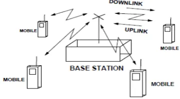
Figure 2. Uplink and downlink channels and system configurations
There are two types of wireless links based on the direction of transmission. The uplink is the link from the mobile (cell phone) transmitter to the base-station receiver and the downlink is the link from the base-station transmitter to the mobile cell phone receiver
(Figure 4). There are differences in the way the uplink and the downlink are modeled, both in terms of channel properties and the algorithms used.
The multi-user detection and synchronization algorithms in the base-station receiver have knowledge of the spreading sequences of all the users. The algorithms used in the mobile receiver are typically “blind" (i.e. they can work without the need for the knowledge of the spreading sequences of the other users). The blind schemes are also required to be computationally less demanding due to the limited processing power in the mobile unit.
IV.
SIMULATION RESULTS
This section presents the simulation results for the WCDMA system at different channel conditions. Simulation results include BER/Frame Error Rate (FER) vs Eb/N0 and BER vs Number of interferers. Improvement in BER due to error correction coding scheme is shown for a 9.6 kbps uplink service.
Uplink Simulation Results
The following figures show the BER vs Eb/N0 curves for different number of users. The
Figure 3. BER vs Eb/N0 at the WCDMA Uplink for Indoor Channel.
spreading factor at the data channel is 32. The channels are Indoor channel and Vehicular A Outdoor Channel. The simulation resolution is 5 samples per chip. We assume that the received signals from all the users at the base station have equal power, i.e. we have perfect power control.
34
Figure 4. BER vs Interferers at the WCDMA Uplink for Indoor Channel. (Eb/N0 is 12 dB)
We can observe from the figures that as the system load reach 50%, the BER approaches to 10% which obviously is unacceptable. However with error correction coding and antenna diversity schemes, the BER can be pushed back to an acceptable limit.
Downlink Simulation Results
BER performance at the downlink is presented in this section. The following figures illustrate the BER vs Eb/N0 curves at the downlink for different number of interfering users. The simulation resolution is 5 samples per chip. BER for both Indoor channel and Vehicular A Outdoor channel is shown. The spreading factor is 32. We assume that the signals for all the users are transmitted at equal power.
Figure 5. BER vs Eb/N0 at the WCDMA Downlink for Indoor Channel.
Figure 6. BER vs Eb/N0 at the WCDMA Downlink for Vehicular A Outdoor Channel
V. CONCLUSION
We implemented a signal simulator according to the physical layer specification of the IMT-2000 WCDMA system. The data is transmitted in a frame by frame basis through a time varying channel. The transmitted signal is corrupted by multiple access interference. The signal is further corrupted by AWGN at the front end of the receiver. Simple rake diversity combining is employed at the receiver.
We investigated the bit error rate at both uplink and downlink for two different time varying channels. As expected the system is interference limited for higher number of users.
We observed that without any channel coding schemes and antenna diversity techniques, the BER approaches to 10% as the system load goes beyond 50%. This is not an acceptable performance. However the BER can be pushed back to an acceptable limit with channel coding and antenna diversity techniques.
35
REFERENCES
[1] T S Rappaport, B D Woerner, and J H Reed,
Wireless Personal Communications, Kluwer Academic
Publishers, 1996.
[2] Raymond L. Pickholtz, Donald L. Schilling, and Laurence B. Milstein, “Theory of Spread Spectrum Communications - A Tutorial," IEEE trans.
Communications, vol. COM-30, no. 5, pp. 855-884, May
1982.
[3] Joseph Cavallaro and Behnaam Aazhang, “Development of a Testbed for Wireless Multiuser Communication Systems," Project Definition Document (See CMC Web Page), 1998.
[4] WINLAB at Rutgers Univ., “Wireless Propagation and Protocol Evaluation Testbed (WiPPET)," Website - http:// www.winlab.rutgers.edu/ pub/projects/ Fall98/ Modeling and Simulation.html, 1998.
[5] Hewlett Packard Labs, “Simulated BER Performance of, and Initial Hardware Results from, the Uplink in the U.K. LINK-CDMA Testbed," Tech. Rep. http://www.hpl.hp.com/techreports/96/HPL-96-80.html, May 1996.
[6] Center for Multimedia Communications at Rice University (C M C) “http://www.ece.rice.edu/COMM," C M C Web Page, 1999.
[7] Shimon Moshavi, “Multiuser Detection for DS-CDMA Communications," IEEE Communications
magazine, pp. 124-136, Oct. 1996.
[8] Kurt Matis, “Design, Simulation, Analysis of CDMA Communication Systems," Tech. Rep., ICUCOM Corporation, 1997.
[9] Cadence Inc. Alta Group, “Signal Processing Work
system (SPW) at http://www.cadence.com/alta/products/," Cadence
Website, 1997.
[10] Synopsys Inc., “COSSAP http://www.synopsys.com/products/dsp/dsp.html,"