http://www.sciencepublishinggroup.com/j/ajwse doi: 10.11648/j.ajwse.20190501.15
ISSN: 2575-1867 (Print); ISSN: 2575-1875 (Online)
The Research of the Flow Characteristics in Spiral
Membrane Separator
Zhou Xiantao
*, Liu Hui, Wan Xuhui
Institute of Chemical Machinery, East China University of Science and Technology, Shanghai, China
Email address:
*Corresponding author
To cite this article:
Zhou Xiantao, Liu Hui, Wan Xuhui. The Research of the Flow Characteristics in Spiral Membrane Separator. American Journal of Water Science and Engineering. Vol. 5, No. 1, 2019, pp. 29-36. doi: 10.11648/j.ajwse.20190501.15
Received: January 24, 2019; Accepted: March 17, 2019; Published: April 8, 2019
Abstract:
The spiral membrane separator is a novel module proposed for reducing the concentration polarization and membrane fouling of membrane separation process. This membrane separation process benefits from dean vortices produced by centrifugal instability in enhancing fluid mass transfer. A numerical stimulation of this membrane separation is presented and used to analyze the fluid flow characteristics and thoroughly understand the separation mechanism. The numerical model consists of a spiral flow path with rectangular sector. As the simulation with infiltration, the fluid domain of the ceramic membrane tube was as a porous medium domain. The standard momentum equation, added with the momentum equation source term which composed of the viscosity loss term and the inertia loss term, are figured out through the experimental characterization. In the simulation of spiral membrane separation, the Dean secondary flow structure is identified and found to enhance fluid mass transfer and to increase the permeate flux. The critical unstable state of spiral membrane separation is accordingly De=246 without the flow permeation and De=863 with the permeation, where Dean vortices cause collisions and the mixing of fluid particles. Then in the case of permeation, the fluid in separator at De=1232 is numerically simulated to show that the higher flow velocity and a large fluctuating trend of wall shear stress near the membrane surface (inside), which mainly contributed to alleviate concentration polarization and membrane fouling.Keywords:
Membrane Separation, Secondary Flow, Numerical Simulation1. Introduction
During the pressure-driven membrane separation process, the suspension flows towards the membrane surface of the membrane where separation and a simultaneous slow diffusive flow of the particles into the other side of membrane due to a concentration difference occur. This slow transport, coupled with membrane fouling [1], is a major limiting factor in the separation process. A series of methods to reducing the concentration polarization and the deposit, such as feed liquid pretreatment, membrane material selection and modification, mechanical washing and enhanced mass transfer, can be very effective in improving the permeate flux.
There are some studies on the pretreatment feed and membrane material selection and modification have been conducted. Liu Zhongzhou et al. [2] used them to mitigate and control membrane fouling in the microfiltration and
membrane fouling reduction.
However, some pioneering work on the research of mass transfer improvements in pressure-driven membrane applications was performed by Liu Yuanfa [7] and so on. Liu has introduced several methods to suppress membrane fouling from the perspective of enhanced mass transfer and then proposed that strengthening will cause greater energy consumption and it is necessary to evaluate the strengthening method from two indexes: membrane flux and energy consumption. T. Lohaus [8] showed that a local temperature gradient is induced by heating a novel conductive film to cause convection perpendicular to the film, and a convective vortex having a significant shear velocity is formed in the vicinity of the membrane surface such that the accumulated solute is away from the membrane. Takaaki et al. [9], in their experiments installing a spiral baffle around the membrane, obtained a flux increase with respect to membrane without the baffle in the wide feed flow rate range. They indicated that, the swirling motion produced by the spiral baffle around the membrane becomes more dominant at a smaller aperture ratio of the cross-sectional area. Through characterizing the intensity of the fluid motion by the number of vortices, they found that high separation performance was obtained at high vortex numbers.
In addition to these studies, many more researches on the curved membrane channels which provide a high mixing potential by secondary or Dean vortices was performed. Based on the Dean vortex theory a novel vortex-generating tubular nanofiltration element was designed by Hanuman Mallubhotla et al. [10]. They used the experimental results to confirm that the flow in the spiral tube produces Dean vortices to enhance the reverse migration of solute, which can reduce concentration polarization and membrane fouling.
Some pioneering work on the fluid characteristics of spiral membrane separation involving Dean vortices. Liu, L. [11] examined the mass transfer performance of the crimped hollow fiber membrane module by experiments and found that, on either side of the membrane, the mass transfer coefficient of the coiled module is more than 2 times higher than the one of the linear-module. Kaufhold, D. a [12] applied Dean vortices to improve the fluid transfer rate and researched how the flow rate affects mass transfer. Jie, L. [13] used the PIV technique to demonstrate the difference in intensity and distribution of the flow field/speed vector between the spiral membrane module and the flat one. The author showed that the spiral membrane produces a swirling flow near the membrane surface, increasing the shear rate/flow rate. Ph Moulin [14] proposed to calculate the wall shear stress of the non-porous wall in the process of filtration. Manno, P. [15] found that the secondary flow enhanced membrane penetrated 5 times, and further energy analysis is demonstrated that for the same energy consumption, the permeate flux obtained in the coiled module was still much larger than the permeate flux in the straight module. Bubolz, M [16] indicated that the Dean vortices enhance the filtration flux and efficiency of the crossflow microfiltration process in the spiral coil film, revealing that the increased wall shear stress leads to the
reduction of particle deposition and the increase of mass transfer.
Some other researchers have studied the effects of different conditions on secondary flow. R. moll [17] calculated the corresponding three-dimensional velocity field to study the velocity profile and local wall shear stress for permeable and impermeable fibers. Seyed Pouria Motevalian [18] simulated the flow of twisted elliptical fibers and spirally coiled cylindrical fibers during membrane filtration.
It can be noted from this brief literature review that, so far, major attempt has been made to demonstrate the flow characteristics of spiral membrane separation with circular section. The work of this paper aims to study the fluid flow characteristics of spiral membrane separator and complements the missing numerical simulation work in spiral membrane modules with rectangular section.
2. Dean Secondary Flow Phenomenon
The fluid in the curved pipe pushed by the centrifugal force flows from the inner side wall of the pipe to the outer side wall surface with forming the low-pressure area inside the elbow and then flows reversely under the effect of pressure difference with forming a pair of counter-rotating symmetric vortices which is perpendicular to the cross section, that is, Dean secondary flow. The Dean eddy currents were firstly discovered in 1927 by Dean WR who pointed out that the generation of the Dean secondary flow attributed to the interaction of centrifugal and viscous forces of the tube fluid and proposed the dimensionless number De to measure the intensity of the Dean vortex. Defined as
= (1)
Where Re is the Reynolds number, Dh is the curved channel hydraulic diameter, and Dc is the diameter of curvature of the curved pipe. According to the study of David [19], the Dean number of spiral flow features can be calculated according to the following equation for a spiral flow with rectangular cross-section:
= (2)
Where R is radius of the spiral pipe, K = P/2π, P is the screw pitch.
From the flow characteristics of the spiral flow, it can be shown that the reduction in both the concentration polarization and the membrane fouling, and the increase in the permeation flux can be predicted in the spiral membrane separation process.
3. Introduction of New Spiral Membrane
Module Structure
deflector) with a rectangular-section spiral channel surrounded by these parts. The suspension accomplishes separation process in this spiral path where the filtrate continuously permeates through the ceramic membrane tube under a certain operating pressure while the solid particles move to the outside of the tube by the centrifugal force with
less deposition of solid particles on the membrane surface. Besides, Dean secondary flow cause by fluid flow instability in the spiral channel further strengthens the membrane separation process and reduces concentration polarization and fouling.
Figure 1. Spiral membrane module diagram.
This paper is to develop a numerical model of membrane separation and to use this model to investigate its separation mechanism.
4. Experimental Characterization of
Porous Medium Characteristic of
Ceramic Membrane Tubes
4.1. Porous Medium Characteristic of Ceramic Membrane Tubes
The Fluent often treats the membrane part as a porous medium area and the role of the solid structure in the fluid zone as attaching distribution resistance to the fluid during the simulation of membrane separation. The momentum equation of the porous medium model is to increase the momentum equation source term which composed of the viscosity loss term (Darcy) and the inertia loss term in the standard momentum equation:
= ∑ ∑ | | " (3)
Where Si is the source term of the momentum equation, |v| is the velocity magnitude, µ is the fluid viscosity, ρ is the fluid density, and D and C are the matrices. The source term of the momentum equation has an effect on the pressure gradient in the porous medium region with creating a pressure drop proportional to the velocity (or velocity squared). Then the momentum equations can be reduced to pressure drop and momentum source terms:
#p = (4) Or Δp = Δ& (5)
Where ∆n is the actual thickness of the porous media.
For isotropic porous media, the formula can be simplified to:
= *+ | | " (6)
Where 1/α is the viscous drag coefficient and C2 is the inertial drag coefficient.
4.2. Experimental Procedure Characterizing the Porous Media of Ceramic Membrane Tubes
The experimental data of pressure drop and velocity can be used to obtain.
The viscous drag coefficient and inertial drag coefficient of the porous media region on basis of the above discussion. The experimental principle diagram is as follows:
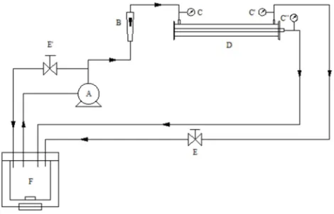
Figure 2. Schematic representation of experimental apparatus.
A. Pump; B. Flowmeter; C, C’, C”. Pressure gage; D. Module; E, E’. Valve; F. Groove
through the membrane module (D) and returns as filtrate and retentate to the water tank to maintain its stability of the water level. The inlet flow rate of the membrane module is controlled by the bypass valve (E‘) and the valve (E) at the outlet of the retentate is gradually closed to adjust the filtration pressure of the membrane module. The inlet pressure and outlet pressure are measured by the pressure gauges C and C’ respectively with the outlet pressure of the filtrate being measured by the pressure gauge C” . The pressure drop of water permeating the ceramic membrane tube is
approximately ∆p =, ,- C". The flux of the filtrate was measured by the measuring cylinder and stopwatch indirectly and then the flow velocity of the filtrate was calculated based on the membrane area and the flux with the water temperature remained at approximately 20°C.
4.3. Characterization of Porous Media Characteristics of Ceramic Membrane Tubes
The flow rate and pressure drop of the filtrate through the ceramic membrane tube are shown in Table 1.
Table 1. Filtrate flow rate and pressure drop through the ceramic membrane tube.
Velocity/(m/s) Pressure drop/(Pa) 5.50 3 1056 4000
6.70 3 1056 5000 7.05 3 1056 5800 8.29 3 1056 7800
A “velocity-pressure drop” curve can be fitted in the data in the above table. The equation can be calculated with the correlation R=0.996:
∆P 8.5532 3 10< 2.18919 3 10= (7)
The ceramic membrane tube thickness in the experiment is ∆n 3mm, the water density at 20°C is ρ 998.2kg/B , the dynamic viscosity is μ 1.003 3 105 DE ∙ G. Based on the formula (5), (6) and (7), the viscous drag coefficient and the inertia drag coefficient can be calculated as
+ 7.2973 3
10 , C 5.7021333 3 10<.
The characteristics of the porous media of the ceramic membrane tube obtained through the experimental characterization—the viscous drag coefficient and the inertial drag coefficient will be used as the viscosity loss term and the inertia loss term coefficient of the momentum equation’s source term in the porous media model when simulating the membrane separation.
5. Numerical Simulation of Flow in
Separation Process of Spiral
Membrane
5.1. Physical Model
The rectangular section spiral channel is surrounded by
outer tube, ceramic membrane tube and rectangular cross-section deflector. The inner and outer diameters of the outer cylinder were 44mm and 50mm. The inner and outer diameters of the membrane tubes were 24mm and 30mm, and the length was 1000mm. That the spiral deflector in 15mm pitch, 60 turns, 7mm width and 2mm thickness forms a spiral flow path with a spiral radius of 18.5mm and a pitch of 15mm (13:7 section ratio).
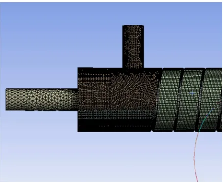
5.2. Meshing and Simulation Methods
The fluid flow in the spiral channel with rectangular cross-section was numerically simulated by the Fluent with regarding water as the fluid medium. The meshing is shown in Figure 3 divided by the meshing platform in ANSYS Workbench 12. Considering the complex geometric structure, the segmentation method is adopted, which the flow field in different areas is divided into different methods and the adjacent face of the connection block is set as an interface to ensure that the flow field calculation domains of different parts can be connected. For considering the computer load and the calculation accuracy requires that the grid size is 1mm and there is a boundary layer. Model selection: The Reynolds number can be calculated by boundary conditions (turbulence Re>3 000) and further used to choose the laminar flow model or the Reynolds stress model (which can simulate strong swirling flow well, curved wall flow, etc.); boundary condition setting: The operating conditions are standard atmospheric pressure; solution method: The SIMPLEC algorithm is used to solve the velocity-pressure field with adopting the finite-volume method to discretize the control equations in the QUICK format, and other equations is in the second order upwind where the calculation accuracy residual is as 10-3.
Figure 3. Spiral membrane separator fluid channel mesh.
As the simulation with infiltration, the fluid domain of the ceramic membrane tube was as a porous medium domain with a porosity of 0.4, followed several assumptions were made in the infiltration model:
axial direction of the membrane tube in the porous media of the ceramic membrane, only the percolation flow of the fluid in the radial direction is considered with the ceramic membrane as an isotropic porous media;
(2)neglecting the influence of gravity on the infiltration process;
(3)Assume that the fluid temperature keeps constant during the separation process.
5.3. Numerical Simulation Reliability
The reliability of the simulation in this paper is mainly verified by the relationship between the inlet velocity and the pressure drop of the model without regarding to infiltration. Figure 4 shows that the simulated pressure drop has the same trend as the experimentally measured pressure drop, which indicates that the experimental results are in good agreement with the simulation results and the simulation results have a certain degree of confidence.
Figure 4. The pressure drop of model with different flow velocity.
6. Results and Discussion
6.1. Critical Operating State of the Spiral Membrane Separator
6.1.1. The Rectangular Spiral Flow Without the Permeate Flow
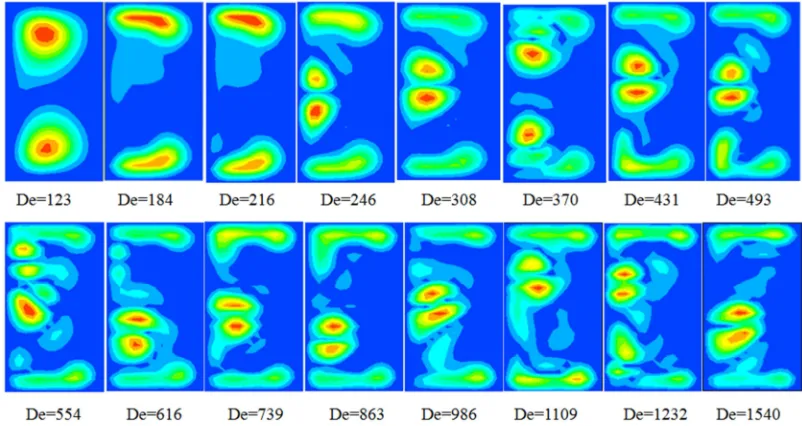
This simulation result uses the flow visualization method of Fellouah [20] to show the secondary flow phenomenon with the helicity outline. The helicity is the dynamic characteristic physical quantity that characterizes the movement of the fluid rotate as well as move in the direction of rotation, as:
H J# 3 KLMNKLM (8)
Figure 5 depicts the distribution of helicity on the rectangular cross-section of the spiral flow without permeate flow. All colors in Figure 5 and Figure 6 indicate that the intensity of the secondary flow where the lighter color features the weaker secondary flow. Initially, at very low flow rates, there are only a pair of angular vortices generated by the curved wall effect and called Ecman vortex; for the case of De = 246, there is another pair of vortices, that is the Dean secondary flow which is formed by the destabilized flow and whose central position is always close to the concave side of the curved pipe wall (left side of the figure). Again, it may be limited to the rectangular cross section (section ratio), there is only one pair of Dean secondary streams with the increase of the Dean's number. However, the additional vortex pairs will account for violent collisions and the mixing of fluid particles, more violent momentum transfer, and relative movement between fluids, which will further increase the energy consumption and pressure drop. However, the trends of both the flow rate and the pressure drop in Figure 4 has no obvious abrupt change point which demonstrates that the fluid flow in the separation of the spiral membrane has caused instability within the above flow rate range.
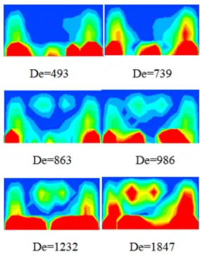
6.1.2. The Spiral Membrane Separator with the Permeate Flow
Under the influence of permeate flow, weakening the flow field, the number of De of the fluid flow instability point in the spiral membrane separation is greater than 246. Figure 6 shows the permeate flow has a significant weakening of the spiral flow field and then the Dean secondary flow is produced at the center of spiral flow between De=739 and De=863. Therefore, the permeate flow accounts for the weaker Dean Secondary flow intensity and then the critical unstable state, that is, the minimum working state of the spiral membrane separator is about De=863.
Figure 6. The spiral contour of the rectangular section spiral flow with permeation.
Besides, as the flow permeate, a secondary flow is formed in the vicinity of the membrane surface due to a part of the fluid moves radially outward under the centrifugal force of the curved flow path and simultaneously moves radially inward under the transmembrane pressure difference. Therefore, the effect of permeation is clearly evident on the inhibition of concentration polarization and fouling in membrane separation.
6.2. Flow Characteristics of Fluid in Spiral Membrane Separator
The fluid with permeation in separator at De=1232 which fully ensuring the fluid flow instability is numerically simulated to analyze separation mechanism from the following aspects:
6.2.1. Speed Distribution Characteristics
This article analyzes the characteristics of velocity distribution near the inner and outer side wall surfaces at 0.5 mm and at the middle diameter:
(1) Axial velocity distribution: Figure 7 indicates that the axial velocity of the fluid near the membrane surface (r=15.5mm) is significantly higher than the axial velocity of the outside fluid (r=21.5mm) and the axial velocity of the inner fluid particle as a near sine distribution, where part of fluid particles’ axial velocity is in the opposite direction, forming a
reversed erosion to the membrane surface. Due to the fluid axially scours the inner wall surface at high speed, the concentration polarization of the membrane module and membrane fouling is largely reduced.
Figure 7. Different radius of axial velocity along the axial position.
(2)The circumferential velocity distribution: Figure 8 shows that the circumferential velocity near the film surface (r=15.5mm) is greater than the circumferential velocity near the outside wall surface (r=21.5mm) doe to the Dean Secondary flow. The suspension particles in the spiral membrane separator will be subjected to centrifugal force due to their density difference and move outward in the radial direction under the action of centrifugal force, so that the concentration of suspension particles near the surface of the film is lower than the one near the outer sidewall surface. Since the membrane separation performance is greatly reinforced by the changed concentration distribution of the suspension, the membrane tube is placed inside the deflector.
Figure 8. Different radius of circumferential velocity along the axial position.
6.2.2. Wall Shear Stress Distribution Characteristics
according to the steady flow penetration theory [21], the permeation flux has a positive exponential relationship with the wall shear stress, which means that the higher wall shear stress will lead to the higher permeation flux. Figure 9 presents that the shear stress near the membrane surface (inside) has a large fluctuating trend due to the angular vortex generated by the wall bending effect and secondary flow on the membrane surface, and the shear stress of the inner sidewall surface is greatly improved.
Figure 9. The inside and outside wall shear stress.
6.2.3. Internal and External Wall Pressure Distribution Characteristics
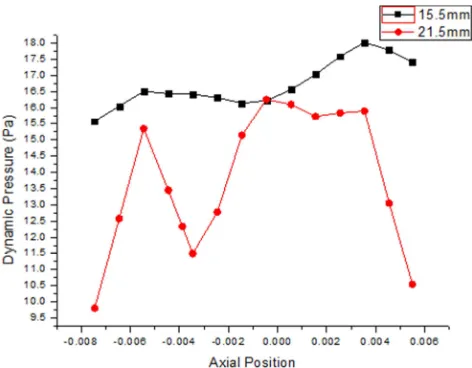
Dynamic pressure and total pressure distribution in the axial direction at a radius of 15.5 mm and 21.5 mm near the wall surface are shown in Figure 10 and Figure 11 respectively: near the film surface (r=15.5mm) the dynamic pressure energy is higher than the one near the outside of the wall, but the total pressure is just the opposite. And the secondary flow makes the internal and external wall pressures both fluctuate, which is beneficial to the reduction of the concentration polarization in membrane separation.
Figure 10. The inside and outside wall dynamics pressure.
Figure 11. The inside and outside wall.
7. Conclusion
The numerical simulations’ results showed that the flow instability occurs around De 246 in spiral flow with rectangular cross section (section ratio of 13:7) and there are no more pairs of Dean secondary flows even if the flow velocity increased. However, the critical working state of the spiral membrane separation with permeate flow is around as high as De 863.
The separation performance of the spiral membrane separator depends on its unique flow field characteristics. And then the concentration polarization and membrane fouling produced during membrane separation are inhibited by the Ecman angular vortex caused by the curved wall effect and the Dean secondary flow caused by the flow instabilities so that the fluid can flush axially the membrane surface and the process can further continue effectively.
References
[1] Zheng Cheng (1997). Membrane pollution and its prevention. Membrane Science and Technology 17, 5-14.
[2] Liu Zhongzhou, Xu Shuguang and Li Suoding (1997). Membrane fouling and cleaning in UF and MF. Technology of Water Treatment 23, 187-192.
[3] J. G. Herterich, I. M. Griffiths and D. Vella (2019). Reproducing the pressure-time signature of membrane filtration: The interplay between fouling, caking, and elasticity. Journal of Membrane Science 577, 235-248.
[4] Wang Xiaolin (2001). Fouling and degradation of membranes and their prevention and control. Industrial Water Treatment 21, 1-5. [5] Liu Zhongzhou, Zhang Guojun and Ji Shulan (2006). Methods
[7] Liu Yuanfa, He Gaohong and Li Baoyu (2006). Research developments of flux enhancement in membrane process. Chemical Industry and Engineering Progress 25, 30-34. [8] T. Lohaus, N. Herkenhoff, R. Shankar and M. Wessling (2018).
Feed flow patterns of combined Rayleigh-Bénard convection and membrane permeation. Journal of Membrane Science 549, 60-66.
[9] Takaaki Akagi, Takafumi Horie, Hayato Masuda, Keigo Matsuda and Yushi Hirata (2018). Improvement of separation performance by fluid motion in the membrane module with a helical baffle. Separation and Purification Technology 198, 52-59.
[10] Hanuman Mallubhotla, Sven Hoffmann, Meike Schmidt, Johan Vente and Georges Belfort (1998). Journal of Membrane Science 141, 183-195.
[11] Liu, L., Li, L., Ding, Z., Ma, R. and Yang, Z. (2005). Mass transfer enhancement in coiled hollow fiber membrane modules. Journal of Membrane Science 264, 113-121. [12] Kaufhold, D. a, Kopf, F. b, Wolff, C. c, Beutel, S. c, Hilterhaus,
L. a, Hoffmann, M. b, Scheper, T. c, Schlüter, M. b and Liese, A. a (2012). Generation of Dean vortices and enhancement of oxygen transfer rates in membrane contactors for different hollow fiber geometries. Journal of Membrane Science 423-424, 342-347.
[13] Jie, L., Liu, L., Yang, F., Liu, F. and Liu, Z. (2012). The configuration and application of helical membrane modules in MBR. Journal of Membrane Science 392-393, 112-121. [14] Ph Moulin, D Veyret and F Charbit (2001). Dean vortices:
comparison of numerical simulation of shear stress and improvement of mass transfer in membraneprocesses at low permeation fluxes. Journal of Membrane Science 183, 149-162.
[15] Manno, P., Moulin, P., Rouch, J. C., Clifton, M. and Aptel, P. (1998). Mass transfer improvement in helically wound hollow fiber ultrafiltration modules Yeast suspensions. Separation and Purification Technology 14, 175-182.
[16] Bubolz, M., Wille, M., Langer, G. and Werner, U. (2002). The use of dean vortices for crossflow microfiltration: Basic principles and further investigation. Separation and Purification Technology 26, 81-89.
[17] R. Moll, D. Veyret, F. Charbit and P. Moulin (2007). Dean vortices applied to membrane process: Part II: Numerical approach. Journal of Membrane Science 288, 321-335. [18] Seyed Pouria Motevalian, Ali Borhan, Hongyi Zhou and
Andrew Zydney (2016). Twisted hollow fiber membranes for enhanced mass transfer. Journal of Membrane Science 514, 586-594.
[19] David L (2001). Series solution of low Dean and Germano number flows in helical rectangular ducts. International Journal of Thermal Sciences 40, 937-948.
[20] Fellouah H (2010). The Dean instability in power-law and Bingham fluids in a curved rectangular duct. Journal of Non-Newtonian Fluid Mechanics 165, 163-173.