73 | P a g e M11-1-1-4-2014
Journal homepage: www.mjret.in
ISSN:2348 - 6953
Prasad Phad
Department of Electrical Engg. K.J. College of Engineering
Pune,India
Minimizing the Penalty in Industrial
Sector by Engaging the Automatic
Power Factor Correction Panel using
Microcontroller
Pranav UkkadgaonkarDepartment of Electrical Engg. K.J. College of Engineering Pune, India
Sagar Jundare
Department of Electrical Engg. K.J. College of Engineering Pune, India
Abhijeet Borse
Department of Electrical Engg. K.J. College of Engineering Pune,India
Abstract
In the industrial sector the various motoring loads are continuously running and generating the inductive load. So the power factor in this system gets reduced due to the inductive reactive power. But the electricity board has a standard limits regarding the power factor values and if the power factor goes below the specified limit; the electricity company charges the penalty to the industrial consumers. The automatic power factor correction panel provides the required compensation to overcome the inductive reactance by using the power capacitors. The microcontroller 8051 receives current signal from current transformer and simultaneously gives the signals to the various contactors to connect the capacitors in the line for the compensation. Thus by adding the capacitor to the line will compensate the reactive power and maintains the power factor near to unity. This will avoids the penalty to the industrial consumers and may get the incentives. In the conventional methods we were using the fixed capacitor for compensation. But these were leading to excessive charging of the capacitors causes the voltage surges. Thus it becomes difficult to main power factor near unity by on and off operation of fixed capacitor. The contactor switched capacitors are connected and disconnected automatically eliminating the previous problem.
74 | P a g e M11-1-1-4-2014
1. INTRODUCTION
The low power factor leads to the increase in the load current, increase in power loss, and decrease in efficiency of the overall system. The various conventional methods for the power factor correction are the using static capacitors, synchronous condensers, phase advancers, etc. in all these methods, the switching of the capacitor or variation of the capacitance is manual. In this paper we are using a method of the reactive power compensation by capacitor switching with automatic control using microcontroller 8051.
2. POWER FACTOR THEORY
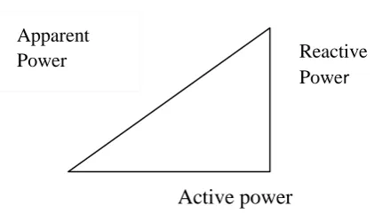
Active power
Fig. 1. Power triangle
The power factor is the ratio of the active power to the apparent power i.e. KW/KVA. The active power is the real power delivered to the loads such as motors, lamps, heating loads, etc. The reactive power is used just for the purpose of producing magnetic field for the flow of active power. The apparent power is the vector combination of the active and reactive power. The load current of any motor consist of the resistive component and inductive component. The inductive component consists of leakage current and magnetizing current. The leakage current is totally dependent on the load current but the magnetizing component is nearby 20% to 60% of the full load current. The capacitors are employed to reduce inductive reactance in the induction motor thereby reducing losses in the supply.
Apparent
Power Reactive
75 | P a g e M11-1-1-4-2014
Fig.2 inductive current vector diagram.
3. MODULES OF THE AUTOMATIC POWER FACTOR CORRECTION
PANEL (APFC)
The various modules in the APFC panel are
Power supply
Transformer
Rectifier
Voltage regulator
Microcontroller (8051)
LCD display
Capacitor bank
Current transformer
Potential transformer
Zero crossing detector
76 | P a g e M11-1-1-4-2014
Fig.3 block diagram of the APFC panel
Power supply:-
Transformer:-
The main function of the transformer I the APFC panel is to step down the input
AC 230V voltage. Then this output voltage is given to the rectifier unit.
Rectifier:-
The main function of the rectifier is to convert the AC voltage into the DC output.
In the APFC panel we are using the bridge rectifier.
Voltage regulator:-
The main function of the voltage regulator is to convert the variable output DC
77 | P a g e M11-1-1-4-2014
a voltage regulator. It gives the two different DC supply for the working of
microcontroller and LCD display.
Microcontroller:-
8051 microcontroller is used in Automatic Power Factor Correction panel. The
microcontroller receives the load current in the line and gives the signal to the relay
driver and simultaneously connects the capacitors as per the requirement.
Steps of automatic operation:-
1) Two signals (voltage & current) are introduced in Microcontroller from line by using C.T and P.T
2) Microcontroller calculates phase angle between this two signals by measuring time interval using timer.
3) Microcontroller calculates the power factor by formula (Cos X phase angle)
4) Then it calculates the required compensation.
5) From given compensation it gives signal to Relay.
6) Then Contactors operate on the relay signal.
7) And required capacitors are added in system.
8) As capacitors are added, power factor gets increased.
9) Power factor is displayed on display of panel.
78 | P a g e M11-1-1-4-2014
Current transformer: The main function of the current transformer is to step
down the current in a measurable value. Basically the C.T. senses the load current in the line. The part of the C.T. is its transformation ratio on which it will transform the current. These ratios are such as 100A/10A, 50A/5A, etc. then this C.T sends the signal to the microcontroller.
Zero crossing detectors: The zero crossing detectors are a sine-wave to
square-wave converter. The reference voltage in this case is set to zero. The output voltage waveform shows when and in what direction an input signal crosses zero volts. If input voltage is a low frequency signal, then output voltage will be less quick to switch from one saturation point to another. And if there is noise in between the two input nodes, the output may fluctuate between positive and negative saturation voltage Vsat. Generally IC 311 is used as a zero crossing detector.
79 | P a g e M11-1-1-4-2014
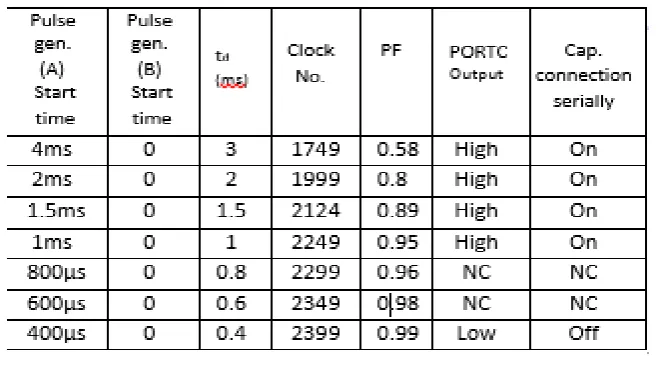
Table 1: Result table
The above table shows that as we reduce down the start time for the pulse generator, the delay time also gets reduced and thus the power factor simultaneously increases and the capacitors are added respectively.
5. CONCLUSION
This paper has proposed the advanced method of the power factor correction by using the microcontroller which has the many advantages over the various conventional methods of the power factor compensation. The switching of capacitors is done automatically by using the contactors and thus the power factor correction is more accurate. Thus we have presented the possible advanced method for the correction of the power factor.
6. ACKNOWLEGEMENT
Each and every effort requires a positive support from the many peoples and areas. We would like to thank our respected HOD Prof. N. M. LOKHANDE. Who permitted and allowed us to carry out project work using the facilities available in the department.
We wish to extend our thanks to the guidance which we receive from our project guide Prof.
SACHIN L. SARAWADE.
7. REFERENCES
[1]. V.K Mehta and Rohit Mehta,“Principles of power system”,S. Chand & Company Ltd, Ramnagar, Newdelhi-110055,4th Edition, Chapter, 6.
[2]. W.Mack Grady and Robert J. Gilleskie , “Harmonics and how they relate to power factor”, Prof. of the EPRI power quality issues & opportunities conference (PQA’93),San Diego ,CA, November 1993.
[3]. P. N. Enjeti and R Martinez, “A high performance single phase rectifier with input power factor correction,”IEEE Trans. Power Electron...vol.11,No.2,Mar.2003.pp 311-317
[4]. J.G. Cho, J.W. Won, H.S. Lee, “Reduced conduction loss zero-voltage-transition power factor correction converter with low cost, ”IEEE Trans.Industrial Electron..vol.45,no 3,Jun. 2000,pp395-400