New presentation - see History box
T
ECHNICAL
November 1992R
EPORT
Source: ETSI TC-RES Reference: DTR/RES-00-03
ICS: 33.060
Key words: Site engineering, radio, mobile service
Radio Equipment and Systems (RES);
Radio site engineering for radio equipment and systems in
the mobile service
ETSI
European Telecommunications Standards Institute
ETSI Secretariat
Postal address: F-06921 Sophia Antipolis CEDEX - FRANCE
Office address: 650 Route des Lucioles - Sophia Antipolis - Valbonne - FRANCE X.400: c=fr, a=atlas, p=etsi, s=secretariat - Internet: [email protected]
Tel.: +33 92 94 42 00 - Fax: +33 93 65 47 16
Copyright Notification: No part may be reproduced except as authorized by written permission. The copyright and the foregoing restriction extend to reproduction in all media.
Whilst every care has been taken in the preparation and publication of this document, errors in content, typographical or otherwise, may occur. If you have comments concerning its accuracy, please write to "ETSI Editing and Committee Support Dept." at the address shown on the title page.
Contents
Foreword ...7
Introduction ...9
1 Scope ...11
2 General...11
2.1 Symbols and abbreviations...11
2.2 Definitions ...13
3 Interference generated on site ...13
3.1 Generation of unwanted products...13
3.1.1 Broadband noise and spurious products of transmitters...14
3.1.1.1 Noise considerations ...14
3.1.1.2 Spurious considerations ...15
3.1.2 Intermodulation products between several source frequencies ...15
3.1.3 Intermodulation products caused by external effects...16
3.2 Intermodulation and blocking effects in receiver systems ...16
3.2.1 Intermodulation between received signals ...17
3.2.2 Saturation of receiver front end ...18
3.2.3 Selectivity of the receiver...18
3.2.4 Spurious response of the receiver...18
3.3 Technical responsibility of the site operator...19
4 Choice of site...19
4.1 General ...19
4.2 Radio site selection criteria ...20
4.2.1 Location chosen by propagation analysis...20
4.2.2 Availability of capacity on existing sites ...21
4.2.3 Compatibility ...21
4.2.4 Environmental and planning considerations...21
4.2.5 Ambient RF noise levels...22
5 Installation recommendations ...22
5.1 Support structure and mechanical considerations...22
5.1.1 Structural integrity...22
5.1.2 Wind loading...23
5.1.3 Protective coatings ...23
5.1.4 Use of dissimilar metals ...23
5.2 Equipment room ...23
5.2.1 Equipment arrangements ...24
5.2.2 Environment ...24
5.3 Electrical supply, protection and lightning protection ...24
5.3.1 Electrical supplies...24
5.3.2 Lightning effects, protection and responsibilities...25
5.3.3 Earthing of antenna support structures ...26
5.3.4 Earthing of antennas, feeders and associated plant ...26
5.4 Antennas and feeders...26
5.4.1 Choice of antenna type...26
5.4.2 Antenna specification ...27
5.4.3 Location of antennas ...28
5.4.4 Radiation pattern ...28
5.4.5 Gain ...28
5.4.6 Cross-polar performance ...28
5.4.7 Voltage standing wave ratio ...29
5.4.8 Wind vibration...29
5.4.10 Cables, cable routes and connectors ... 30
5.4.11 Feeder identification, terminations and earthing... 30
5.4.12 Sealing ... 31
5.4.13 Inspection for moisture ... 31
6 Avoiding radio frequency problems ... 31
6.1 Antenna distribution networks ... 31
6.2 Receiver distribution networks ... 31
6.3 Filters and couplers ... 32
6.3.1 Control of unwanted products... 32
6.3.2 The ferrite circulator... 32
6.3.3 The cavity resonator ... 32
6.3.4 The spectrum dividing filter... 32
6.3.5 Control of intermodulation, cross modulation and blocking effects in receiver systems by filter protection ... 33
7 Environmental effects ... 33
7.1 Standards ... 33
7.2 Corrosion and climatic effects ... 33
7.3 Ultraviolet degradation ... 34
8 Maintenance recommendations ... 34
8.1 Support structure... 34
8.2 Equipment room... 35
8.3 Electrical supply and lightning protection ... 36
8.4 Antennas and feeders ... 36
8.5 Filters and couplers ... 37
9 Site administration ... 38
9.1 Site discipline ... 38
9.2 Site records ... 38
9.3 Orientation of support structure and antennas... 39
9.4 Working arrangements... 39
10 Health and safety ... 39
10.1 Introduction... 39
10.2 Radio frequency radiation ... 39
10.3 Electrical safety ... 39
10.4 Physical safety... 40
10.5 Fire hazards ... 40
11 Troubleshooting on radio sites... 41
11.1 Method of approach ... 41
11.2 Case studies... 41
11.2.1 Cases where the use of cavity resonators, bandpass filters or ferrite isolators provided a cure... 42
11.2.2 Case where the problem is related to equipment alignment ... 43
11.2.3 Cases where the problems are related to broadcast transmitters ... 43
11.2.4 Cases where the problems are related to cables and connectors... 45
11.2.5 Cases where the problems are related to site maintenance ... 45
11.2.6 Cases where the problems are related to faulty equipment ... 46
11.2.7 Case where the problem is related to site modifications ... 46
11.2.8 Case where the problem is related to equipment screening ... 47
11.2.9 Accidental operation of discarded equipment... 47
11.2.10 Examples of lack of isolation between systems ... 47
Annex A (informative): Protection ratios and minimum field strengths required in the mobile services. 48 Annex B (informative): Spectral parameters for TX-RX compatibility ... 55
Annex C (informative): Control of precipitation noise ... 58
Annex E (informative): The position of metals in the galvanic series...60
Annex F (informative): Equipment arrangements ...62
Annex G (informative): Typical example of good earthing practice ...63
Annex H (informative): Common antenna configurations ...64
Annex J (informative): Stacking and baying data ...65
Annex K (informative): Isolation between antennas...67
Annex L (informative): Achieved Cross Polar Discrimination (CPD) for antennas mounted at an angle to precise horizontal and vertical frames of axes ...68
Annex M (informative): Antennas and feeders ...69
M.1 Calculation of system reflection performance ...69
M.2 Points of note concerning the reflection performance of RF systems...70
M.3 Calculation procedure for system reflection performance...70
M.4 Reflection performance calculations for radio site designers...70
M.4.1 Voltage reflection coefficient method...70
M.4.2 Recommended procedure ...70
M.4.3 Calculation example...71
M.5 Reflection performance calculations for radio site engineers ...72
M.5.1 Return loss method...72
M.5.2 Recommended procedure ...72
M.5.3 Example calculations ...73
Annex N (informative): Characteristics of distribution amplifiers...77
N.1 Receiver distribution amplifier system...77
N.2 Receiver distribution amplifier in a 4 way multicoupler system ...78
Annex P (informative): Interference due to intermodulation products in the land mobile service between 25 and 1 000 MHz...79
Annex Q (informative): Sources of unwanted signals in multiple base station sites in the land mobile service ...86
Annex R (informative): Intermodulation interference...89
Annex S (informative): Ferrite isolators and circulators ...94
S.1 Introduction...94
S.2 General...94
S.3 Typical applications ...94
S.4 Ferrite isolator construction ...97
Annex T (informative): Cavity resonators...98
T.1 Introduction...98
T.3 Typical applications ... 98
T.4 Cavity resonator construction ... 100
T.5 Alignment... 101
Annex U (informative): Typical filter system ... 103
Annex V (informative): Trunking combiner ... 108
V.1 UK Band III trunking combiner... 108
V.2 TX/RX Trunking Combiner ... 109
Annex W (informative): Transmitter noise measurement... 110
W.1 Introduction ... 110 W.2 Measurement system ... 110 W.3 Measurement accuracy ... 111 W.4 Results... 111 W.5 Explanation of plots ... 117 W.6 Conclusions ... 117
Annex X (informative): Bibliography ... 118
Foreword
This ETSI Technical Report (ETR) has been prepared by the Radio Equipment and Systems (RES) Technical Committee of the European Telecommunications Standards Institute (ETSI).
The growth of radio services has resulted in an increase in the number of radio sites required and in the number of users sharing their facilities.
The radio frequency spectrum is a finite natural resource for which there are many competing demands, therefore radio systems must be designed so that individual systems are very efficient and operate with minimum interference to other systems.
The aesthetic impact of radio structures provides an increasing constraint on the development of further radio sites. It is essential, therefore, to obtain the support of the community with regard to environmental issues. Consequently it is necessary to demonstrate that the optimum use will be made of the proposed installation.
In granting building permission for a radio structure, local authorities expect radio system users to operate the maximum number of systems from existing structures before giving consideration to an application for another structure in the same area.
Whilst this ETR has been prepared to assist radio system designers to obtain optimum use of radio sites and the radio spectrum, it is also intended for the guidance of those site operators and maintenance organisations who do not have ready access to radio systems engineers.
Accordingly the document sets out methods and design solutions which are achievable without extensive resources.
ETRs are informative documents resulting from ETSI studies which are not appropriate for European Telecommunication Standard (ETS) or Interim European Telecommunication Standard (I-ETS) status. An ETR may be used to publish material which is either of an informative nature, relating to the use or application of ETSs or I-ETSs, or which is immature and not yet suitable for formal adoption as an ETS or I-ETS.
Introduction
Radio equipment for the mobile and fixed services is built to standards which are directed to ensure the efficient use of the radio spectrum. One set of parameters control bandwidth and the level of out of band radiation, which will cause interference to other users, and will specify the receiver sensitivity and limits to the levels of spurious emission from receivers. Another set of parameters define conditions which make a system less susceptible to interference by others; they include receiver selectivity, dynamic range and blocking characteristics. Good installation design ensures that as far as possible the performance of a complete installation preserves the professional characteristics of the components, laying down the intended field strength in the designated area, avoiding the radiation of spurious emissions and preserving the sensitivity of receivers.
The objectives are as follows:
a) to obtain the coverage required from the chosen site in a precise and well defined manner; b) to minimise spectrum pollution to other users on adjacent sites;
c) to minimise interference to other co-sited users;
d) to operate the system with the effective radiated power (erp) and optimum spectral efficiency compatible with providing the required service;
e) to minimise the effects of lightning.
To fulfil the requirements of all relevant legislation and recommendations, the above criteria should be met for the whole of the working life of the installation and should allow for future expansion. The quality of service is largely dependent on the planning of the system and considerable guidance on the topic is given in Annex A.
The layout of this ETR follows the logical approach that would be adopted in the provision of a new radio site, from the selection of a suitable geographic location to the installation and maintenance of radiocommunications equipment. It must be stressed that the order in which these subjects are discussed is not in order of importance. It is therefore essential to read the ETR in its entirety after which it may be used as a reference document.
Preventive maintenance and repairs will be required to ensure that the installation continues to meet the performance criteria described; good engineering design will allow these activities to be carried out safely and with minimum loss of service.
1
Scope
This ETSI Technical Report (ETR) provides guidance for engineers concerned with the design, specification, installation, operation and maintenance of radio systems. It is particularly directed towards systems working in the VHF and UHF bands with a measurement range between 9 kHz and 4 GHz where co-sited operation of many different users' equipment has become common. It does not specifically cover the technology associated with microwave systems.
The ETR examines the objectives of good design and the effects of common deficiencies. It provides recommendations designed to ensure that users avoid interactions which result in mutual interference, spectrum contamination, or danger to personnel or equipment. References and annexes are provided for further reading by engineers who are new to the field or are encountering the problems which are described for the first time.
This ETR also includes information relating to the safety precautions required when dealing with non-ionising radiation.
The contents of this ETR have been arranged to identify the source of the problems found on radio sites and recommendations are made for the control of these problems.
2
General
2.1 Symbols and abbreviations
For the purposes of this ETR, the following abbreviations apply:
ABS Acrylonitrile Butadiene Styrene
ac alternating current
AF Audio Frequency
CCIR Comité Consultatif International des Radiocommunications
CCITT Comité Consultatif International Téléphonique et Télégraphique
C/I Carrier to Interference ratio
C/N Carrier to Noise ratio
CPD Cross Polar Discrimination
dB decibel
dBc decibel relative to carrier
dBd decibel relative to a half wave dipole
dBi decibel relative to an isotropic radiator
dBm decibel relative to one milliwatt
dc direct current
ELCB Earth Leakage Circuit Breaker
EPIRB Emergency Position Indication Radio Beacon
ETR ETSI Technical Report
ETS European Telecommunication Standard
ETSI European Telecommunications Standards Institute
GHz Gigahertz Hz Hertz IF Intermediate Frequency Intermod Intermodulation kHz kilohertz km kilometre kW kilowatt MHz Megahertz m metre mm millimetre
MTBF Mean Time Between Failure
mW milliwatt
NRJ Non-Reciprocal Junction
PA Power Amplifier
PIB PolyIsoButylene
PMR Private Mobile Radio
PVC PolyVinylChloride
RCCB Residual Current Circuit Breaker
RCD Residual Current Device
RF Radio Frequency
RX Receiver
TC-RES Technical Committee-Radio Equipment and Systems
TX Transmitter
UHF Ultra High Frequency
V Volt
VHF Very High Frequency
VSWR Voltage Standing Wave Ratio
2.2 Definitions
Communal site: is a location at which there is more than one fixed transmitter. There are two types of
communal site; one having separate equipment and antennas but housed in a common equipment room, and the other having an engineered system employing common antenna working where the isolation between equipments is determined by the filter system.
At all communal sites equipment installed on the site must meet the limits as specified in the relevant standards.
Single fixed station: only one Radio Frequency (RF) carrier can be radiated at any one time; the fixed
station equipment is only required to meet the limit specified for intermodulation attenuation. All other limits in the relevant standard should be met.
Multiple fixed station: when two sites are in close proximity the decision governing when they should be
classed as a single site or two sites shall be decided by the RF isolation between them. The limiting minimum figure shall be 60 dB but this figure should ideally exceed 70 dB at all frequencies of operation. In any case any signal received from a neighbouring site should not exceed - 20 dBm and ideally - 30 dBm.
Spurious emissions: spurious emissions are emissions at frequencies other than those of the carrier and
sidebands associated with normal modulation.
3
Interference generated on site
The rapid development of mobile radio, particularly within large cities in Europe, produced a wide range of technical and operational problems as a direct result of hurried and badly thought out arrangements on radio sites.
A particularly significant factor was the almost total disregard for technical co-ordination between users on radio sites, and indeed many installations were provided without thought for adjacent systems.
There was also the primitive instinct to provide the highest possible antenna position for each and every system and a separate antenna for every transmitter. These antennas were often fed by poor quality and badly arranged feeder cables which were terminated in a careless way using cheap connectors.
The results merited a great deal of rectification in the 1980s' and one of the major factors that brought about improvements was the proliferation of interference causing loss of service in nearly all the mobile radio bands. This ETR highlights the sources of interference and offers solutions that are practical and effective.
3.1 Generation of unwanted products
Three main sources of radiated products are capable of disturbing other equipments on the same site or on another in close proximity:
a) broadband noise and spurious products of transmitters; b) intermodulation products between several source frequencies; c) intermodulation products caused by external effects.
The apparent nature of the disturbance may be:
1) unwanted received signals which do not result from transmissions on that frequency by the intended user or any other operator sharing the frequency. The signals may or may not contain modulation although in many cases they are overmodulated (distorted) and they may contain a composite of the modulation from several sources; or
Disturbances of type 1) may be identified with relative ease since the unwanted signals are heard in between wanted transmissions or they are of sufficient magnitude that wanted signals are occasionally obliterated. Disturbances of type 2) are more insidious since they cannot be heard by the operator. The effect causes a degradation of receiver sensitivity and a reduction in effective range. The operator may not notice the change or he may mistakenly blame poor propagation conditions.
All these problems show the importance of having adequate isolation between equipments and sites. The ultimate design aim is to preserve the quality of service from the site by eliminating, or at least minimising, receiver disturbance.
It is usual to decide a system target figure for the sensitivity degradation of the base station receiver which is acceptable when caused by the operation of co-located or neighbouring transmitters. For example, it may be decided that a 1 dB sensitivity degradation is acceptable for any one transmitter operating alone, or 3 dB for the worst multiple transmitter combination.
3.1.1 Broadband noise and spurious products of transmitters
All practical transmitters generate unwanted outputs as well as the wanted carrier frequency. Internally generated broadband noise may occupy a significant bandwidth on both sides of the carrier frequency (fc) while spurious outputs may be found at the harmonic frequencies 2fc, 3fc, 4fc...
Frequencies which are not harmonically related may be affected by spurious emissions from some transmitter designs. For transmitters which generate the final carrier frequency (fc) by frequency multiplication of a lower fundamental frequency (fx) the frequencies fc + fx and fc - fx are particularly at risk. The current technologies applied to transmitters give reasonable performances compared to the limits of standards but, at radio sites where many equipments may be co-located, a specific analysis must be performed to decide whether additional measures are necessary to avoid disturbances to receivers.
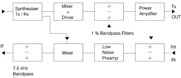
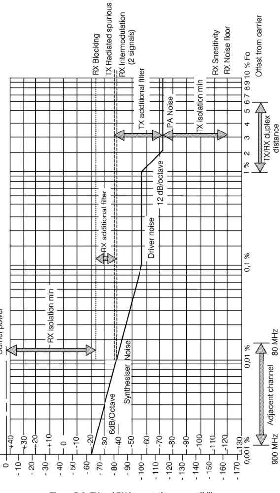
The minimum isolation required between equipments, or the requirements for additional filtering to transmitters, is calculated by the comparison of transmitter noise and spurious emissions with the usable sensitivity and noise floor of receivers.
The notes that follow give an example of the parameters that will apply (see Annex B for more detail).
3.1.1.1 Noise considerations
In considering the effects of noise, receiver bandwidth must be taken into account. For the equipment in use for mobile radio, the worst degradation of sensitivity is obtained for the 12,50 kHz channel spacing standard having a usable bandwidth of 7,50 kHz.
Typical modern receivers for the 12,50 kHz channel spacing standard have a usable sensitivity of - 110 dBm, corresponding to a signal to noise ratio of 10 dB and a noise floor of - 120 dBm.
Additional noise power from external sources of - 120 dBm in the 7,50 kHz bandwidth will degrade the receiver sensitivity by 3 dB.
For 1 dB degradation of sensitivity the noise power from external sources cannot exceed - 126 dBm in 7,50 kHz.
The noise floor of the present generation of transmitters may be expected to be approximately - 140 dBc/Hz within 1 % of fc and - 150 dBc/Hz elsewhere.
The Transmitter (TX) power relative to carrier in the usable bandwidth of 7,50 kHz (+ 39 dB relative to 1 Hz) therefore approximates to - 140 + 39 = - 101 dBc within 1 % of fc or - 150 + 39 = - 111 dBc elsewhere.
Assuming the maximum power of transmitters to be + 43 dBm (20 Watts) the noise power generated by a single transmitter, measured in the 7,50 kHz Receiver (RX) bandwidth, may be expected to be - 101 + 43 = - 58 dBm within 1 % of fc or - 68 dBm elsewhere.
It follows that to safeguard a receiver from a single transmitter by ensuring that the sensitivity degradation during transmission is less than 1 dB, where the frequency separation is within 1 % of fc, requires a minimum isolation of - 126 - (- 58) = 68 dB.
For multiple transmitters the noise power is additive therefore the noise power of N identical transmitters at the same frequency spacing from the carrier is greater by a factor of 10 log (N) dB (e.g. the noise power from four 20 Watt transmitters within 1 % of fc is - 58 + 6 = - 52 dBm and the minimum isolation required in the above example would then be 74 dB).
3.1.1.2 Spurious considerations
Where the disturbance to a receiver is a discrete signal such as in the case of a spurious emission, the required RF carrier to interference ratio for satisfactory operation is 14 dB.
For the typical 12,50 kHz channel spacing receiver previously described, having a usable sensitivity of - 110 dBm, this equates to an unwanted input signal level of - 124 dBm.
The limits defined by ETSI in ETS 300 086 [5] state maximum levels for transmitter spurious emissions of - 36 dBm in the frequency range up to 1 GHz and - 30 dBm above that frequency.
Assuming the above receiver is operating at a frequency below 1 GHz, the minimum isolation required from a transmitter having an on channel spurious emission at the maximum allowable level is - 36 - (- 124) = 88 dB. The design of radio equipments is generally such that direct degradation of the receiver by a companion transmitter is avoided when a moderate amount of antenna isolation is provided and if a sensible frequency separation is chosen during frequency planning. For a single fixed station it is usually only necessary to check the isolation from neighbouring sites.
For multiple fixed stations it is necessary to check the isolation from both co-sited transmitters and from those of neighbouring sites. In this case the use of combining systems to communal antennas, offering 10 to 15 dB minimum isolation improvement by filtering, gives total isolations in the region of 70 dB. This figure is generally adequate to avoid spurious problems and allow the simultaneous transmission of 10 to 20 signals each at a power of + 43 dBm.
3.1.2 Intermodulation products between several source frequencies
These products are caused by the mixing of two or more source frequencies which produce well defined signals which may be of a high level. They are usually the result of inadequate isolation between transmitter output stages, which allows coupling of RF energy between them and the generation of products by a mixing process.
The intermodulation factor has been adopted as a standard by which the immunity to these effects may be judged. It may be considered to be the ratio in dB between the unwanted coupled signal level and the level of the third order intermodulation products which are produced by the mixing process.
The applicable limits for intermodulation factor result from the interpretation of existing standard (ETS 300 086 [5]) for fixed stations. The limits are set according to the intended use of the equipment which may fall into one of two categories:
a) normal - use as a single base station operating alone, for which the intermodulation factor is a minimum of 10 dB;
b) special - use at communal sites where many units may be co-located, for which the intermodulation factor is a minimum of 40 dB.
The intermodulation factor facilitates a simple calculation method to determine the level of third order intermodulation products which can be obtained as a result of transmitter coupling.
Example: Two transmitters each having a power output of + 43 dBm are operated on neighbouring sites with a total port to port isolation of 70 dB. The output stage of each therefore receives an unwanted signal of + 43 - 70 = - 37 dBm.
The level of the resulting third order intermodulation products is therefore: - for "normal" intermodulation factor: - 37 - 10 = - 47 dBm;
- for "special" intermodulation factor: - 37 - 40 = - 77 dBm.
Assuming that a receiver exists in the vicinity, tuned to the frequency of one of these products, and if the antenna isolation between the transmitter and receiver is also 70 dB:
- the "normal" transmitters give a disturbing product of - 47 - 70 = - 117 dBm; - the "special" transmitters give a disturbing product of - 77 - 70 = - 147 dBm.
Comparing these levels with a receiver having a usable sensitivity of - 110 dBm for 10 dB RF signal/noise ratio it is evident that the product of the "normal" transmitters will exceed low level wanted signals on that frequency and will give unacceptable disturbance. The products of the "special" transmitters are well below the receiver noise floor and will have no discernible effect.
This short calculation, which has been applied to identical signal levels, can also be applied to transmissions of any signal level. It shows the importance of intermodulation problems which must be carefully examined when determining frequency planning.
3.1.3 Intermodulation products caused by external effects
The metallic contacts in masts and antenna hardware can be a source of problems when high field strengths occur on the site and cause them to radiate intermodulation products which disturb equipments at the same site, or at a neighbouring site.
No standards exist that are able to specify reasonable limits for such effects. The intermodulation factors used to make these calculations are affected by many parameters and they also depend on electrical resonances in the components which make up the mast and antenna arrays.
The only way to minimise these problems is to follow the guidelines presented elsewhere in this ETR and should problems occur, to make measurements to locate the origin and establish the necessary modifications to effect a cure.
3.2 Intermodulation and blocking effects in receiver systems
These problems are usually a result of large signals at the input of a receiving system which cause non-linearity. There are four different sources:
a) intermodulation between received signals; b) saturation of receiver front end;
c) inadequate receiver selectivity; d) receiver spurious responses.
Although all operational parametres for receivers are well defined by existing ETSs and I-ETSs used in the Land Mobile Service (LMS), the effect of receiver distribution amplifiers must be considered in addition to
these traditional standards since the amplifiers often operate in a hostile RF environment on densely utilised sites.
There is a need to define two bandwidths in the receiving system:
1) the usable bandwidth of the receiver when properly aligned on the allocated channel;
2) the RF front end bandwidth of the receiver system whether this is the preselector filter of the receiver RF amplifier or the input filter of an RX distribution system.
3.2.1 Intermodulation between received signals
The reception of high level signals, within the bandwidth of the first RF filter, is the worst case of intermodulation in a receiver system. The bandwidth and out of band attenuation of this filter is therefore very important.
On a communal site, a high performance preselector filter is generally placed at the antenna input to the distribution amplifier to define the operational frequency band.
For angle modulation systems, receiver intermodulation performance is defined by the existing standard ETS 300 086 [5] as a ratio between an on-frequency wanted test signal of - 107 dBm and two off-frequency unwanted signals at 70 dB above this level displaced to cause a third order intermodulation product on the wanted channel. Under these conditions an audio output approximately equivalent to a 7 dB RF carrier to interference ratio at the receiver input must be obtained. This definition therefore accepts that in the presence of the off-frequency signals, the receiver sensitivity required by standards may be degraded by 3 dB.
The practical result of this definition is that for unwanted input signals at third order related frequencies, the receiver which just meets intermodulation standards experiences a 3 dB sensitivity degradation when the unwanted signals exceed - 107 + 70 = - 37 dBm. This represents a minimum isolation from other 20 W or + 43 dBm transmitters of 80 dB.
In the case of receivers which exceed the minimum sensitivity required by standards, the degradation caused by intermodulation may be much higher. For example, a receiver with a sensitivity of - 110 dBm which just meets the intermodulation standard at - 107 dBm, has in fact been degraded by approximately 6 dB.
Considering the RF level of the product as a signal at the receiver input, the 7 dB carrier to interference ratio relative to a - 110 dBm wanted signal represents an equivalent interfering signal level of - 117 dBm.
Since the receiver encounters an intermodulation product as a discrete frequency and not as simple wideband noise, the required RF carrier to interference ratio for a 1 dB degradation of sensitivity is identical to the case of transmitter spurious and must be 14 dB or greater, dictating a maximum equivalent interfering signal of - 110 - 14 = - 124 dBm.
For a design aim of 1 dB sensitivity degradation due to intermodulation, to a receiver of sensitivity - 110 dBm, the equivalent interfering signal level suggested by standards is too high by 10 dB.
Due to the cubic power law of intermodulation products, the level of the actual unwanted signals is therefore too high by at least 10/3 or 3,33 dB, requiring isolation from the culprit transmitters of 80 + 4 = 84 dB when rounded to the nearest whole number.
When considering transmitters on the same site, appropriate frequency planning in conjunction with filtering can achieve the isolation figures required by the design aim.
The isolation figure is also achievable from mobiles when sites are situated away from busy roads or other areas having a high concentration of mobile transmitters.
Difficulties may arise when considering isolation from other sites if the physical separation or the frequency planning of neighbouring sites are inadequately co-ordinated.
This results in the necessity for critical attention to the bandwidth of the receiver systems at radio sites. Receiver distribution amplifiers must be arranged with precisely defined bandwidths and they must have an intermodulation performance at least 10 dB better than that required by standards. For example, two input signals of - 30 dBm produce third order intermodulation products of - 120 dBm equivalent to a third order input intercept point of + 15 dBm for a unity gain system.
The design aim in receiver distribution systems should always be that the performance is limited by the performance of the receivers themselves rather than the distribution amplifier.
Fulfilling the above criteria should ensure that intermodulation problems do not originate in the site receiver system but probably in the neighbouring transmitters themselves. Careful frequency planning and site engineering, if applied to all sites, should minimise these difficulties.
3.2.2 Saturation of receiver front end
The consequence of very high level received signals will be that the front end active devices of the receiver will have a gain reduction resulting in a degradation of sensitivity.
This situation is generally qualified in the existing standards by the blocking performance. The acceptable limits are defined in the same way as for intermodulation which means that the limit stated corresponds to a received signal of - 23 dBm or an isolation of at least 66 dB between source and receiver (assumes + 43 dBm source).
Since this problem is independent of frequency great care should be taken to identify all critical signals within the response of the front end filter of the equipment by monitoring.
This problem highlights the importance of having sufficient isolation between sites in the same frequency bands.
3.2.3 Selectivity of the receiver
This parameter defines the ability of a receiver to reject signals at unwanted frequencies. The selectivity figure not only depends on the characteristic of the intermediate frequency filter but also on the spectral performance of the local oscillator.
The existing standards define a two signal method of measurement taking all these problems into account by looking at sensitivity degradation. The limits refer also to a wanted signal of - 107 dBm and are 60 dB above for the worst case (12,50 kHz channel spacing). This means that great care should be taken with the frequency planning to avoid having signal levels higher than - 47 dBm on adjacent channels in this case and - 37 dBm in a close frequency proximity (up to 5 x channel spacing).
These limits should be reduced by at least 3 dB in the case of using the full sensitivity performance of a site (i.e. - 50 dBm on adjacent channels and - 40 dBm in close frequency proximity).
3.2.4 Spurious response of the receiver
All receivers have their own frequency conversion plan which can be in either upper or lower mode. The result of this process added to the RF filtering response and to the possible spurious signals of the local oscillators used may be the source of other spurious responses at the RF input, resulting from the complex mixing of signals. The latest ETS standards give well defined methods of measurement for these spurious responses and the calculation of frequencies at which they can occur, (including duplex mode) by taking into account all local oscillator sources.
The limits considered are referred to a - 107 dBm wanted signal and 70 dB above. They are identical to intermodulation limits and the same comments should apply regarding suitable response of all RF filters.
3.3 Technical responsibility of the site operator
It is essential that the site operator is able to quantify any unwanted products which give rise to unreasonable degradation of service to co-sited installations.
Some solutions to the problems arising from unwanted products are offered in Clause 6. There is a need for further procedures to control the lack of co-ordination that often exists between the site operator, the users and the licensing authority.
4
Choice of site
4.1 General
For a proposed service, sites are chosen for their ability to provide coverage of the required service area. Buildings or other existing structures can be used providing a suitable antenna system can be erected. In deciding the suitability of sites, the effects on coverage of local physical obstructions must be taken into account. The final antenna height must be sufficient to clear obstructions if a good radiation pattern is to be achieved.
Preference is usually given to sites centrally located within the required service area so that maximum coverage is achieved with an omni-directional radiation pattern. In the event that no suitable locations can be found it may be necessary to utilise sites on the periphery of the service area. In these circumstances directional antennas would normally be employed to limit radiation to the desired area.
The use of the highest available site is not always the best decision. As more users occupy the available radio spectrum there is an increasing need to share frequencies. The use of an unnecessarily high site may provide degraded service due to co-channel users. Modern systems are frequently designed on an interference limited, rather than a noise limited criteria.
When locations have been identified which meet the coverage requirements, determined attempts should be made to share existing sites with other users. The site sharing decision will be influenced by the availability of sites, their coverage potential and whether RF compatibility exists with the other users' equipment.
If the construction of a new site is necessary the location should be carefully chosen both from the coverage and the environmental and planning aspects. Other radio users should always be informed of the proposals as a large number may wish to expand their systems and share the new facility if it offers significant advantages.
It is essential that all potential users are taken into account in the initial planning of a site. There have been many cases in the past where a multitude of small sites have been erected in close proximity due to lack of early consultation. Co-operation to build a single large structure would mean users could share costs and all would benefit from increased performance of the facility.
To design installations which meet the user's expectations the requirements must be understood and interpreted with the propagation parameters of the frequencies to be used. In certain environments it may be extremely difficult to provide a clear path for the required radiation pattern. The choice of site may be a compromise between radio coverage requirements, technical considerations and economic or planning constraints.
The fundamentals to the choice of radio sites may be summarised as follows:
a) examination of user requirements, service area, frequency, licence power limits, modes of operation; b) inspection of service area to identify preferred locations for sites;
c) search for existing sites in the preferred areas;
e) formulate proposals for new sites where necessary.
The choice of sites is an iterative process that may have to be repeated several times to produce the optimum choice of sites. Where compromises are necessary it is essential that the user is given the opportunity to consider what effects coverage irregularities will have on the service.
4.2 Radio site selection criteria
Radio site selection criteria can be classified as follows: a) location chosen by propagation analysis;
b) availability of capacity at existing sites; c) site compatibility;
d) environmental and planning considerations.
4.2.1 Location chosen by propagation analysis
Propagation analysis is necessary to decide in which areas to search for radio sites, to check the suitability of an existing site, or to decide the exact location for the construction of a new radio site.
Propagation information must be related not only to the site location but also to the power, frequency band, antenna height and type of the system in use. It must account for the screening effects of terrain and clutter e.g. buildings and trees. It must also consider the reception environment of the mobile station which may suffer from man made noise or multi-path fading due to signal reflections.
Propagation information can be obtained by several methods as follows:
a) information from site operators based on their experience of existing sites;
b) manual calculations by an experienced propagation engineer based on map information of terrain height and features;
c) computer field strength predictions generated by evaluating radio path loss from a database of terrain height and feature data;
d) radio survey by the establishment of a test station at the proposed location for the purpose of carrying out coverage measurements.
To identify the areas of search for radio sites, manual calculations from maps are the most appropriate. These may also be adequate to check the suitability of an existing site when they are examined along with the past experiences of other site users.
To decide the location of a new site computer predictions are strongly advised. These are available from a number of commercial organisations. However, it should be appreciated that they are statistical in nature and subject to local variations. The magnitude of the variations is dependent on the accuracy and resolution of the terrain database used to generate the predications, and the quality of the propagation model.
The most reliable information is obtained by the establishment of a test station and measurement of signal strength across the area of interest. Such tests must be carefully executed to simulate the user's final operational conditions.
4.2.2 Availability of capacity on existing sites
When a suitable existing site has been located there are several options available to the new user and these are as follows:
a) to share an information channel on an existing system;
b) to share a frequency division filter system on an existing antenna;
c) to share the equipment accommodation and install a new antenna on the structure; d) to provide separate equipment accommodation and install a new antenna on the structure.
Each possibility must be evaluated against the users' requirements. The proposals will be affected by various technical and economic limitations.
In the event that there are serious shortcomings in equipment room accommodation, antenna mounting positions or antenna structure load bearing capability a complete site redevelopment may be required. It may be concluded that site sharing is not viable and that an alternative site should be sought elsewhere.
4.2.3 Compatibility
For satisfactory performance of the installed system, radio site compatibility is essential. This covers all RF aspects which may cause interference to or from the proposed system. Compatibility with other users of the same or adjacent sites must be ensured.
Wherever possible the location of a radio structure should be chosen with reference to its isolation from other radio transmission activity. It should preferably be at least 500 metres from a busy road. This is to avoid the reception of vehicle ignition noise and to prevent interference from passing mobile radio transmitters.
The ambient noise level, particularly at urban sites in the lower VHF bands, will have a limiting effect on receiver sensitivity and therefore receiver range and performance. Ambient RF noise includes atmospheric noise and man made electrical noise. Care should be taken to avoid areas of high level man made noise either from industrial or domestic sources. The increased processing speed and greater number of computing equipments in recent years has proved to be a virulent source of radio noise in some cases even affecting the UHF bands. Annex A gives guidelines for ambient noise levels for various frequencies and environments.
The possibility of RF breakthrough into other electronic equipment should be considered. In the past cases of breakthrough to audio and video equipment have been reported due to the siting of radio installations in residential areas. It is important to realise that there are no actions that can be taken at the radio site to eliminate high ambient noise levels and RF breakthrough effects. These can only be reduced by measures which would also drastically affect the wanted coverage area.
Inability to achieve compatibility with local factors or with existing site users may cause the site to be rejected in favour of an alternative site offering better compatibility.
4.2.4 Environmental and planning considerations
Radio sites are prominent features of the landscape. It is therefore understandable that many Building Authorities pay particular attention to applications for new sites and for redevelopment of existing sites. There are also organisations and individuals who will raise objections to any application. Objections will be more numerous where the site is located in a National Park, Area of Outstanding National Beauty or Area of High Landscape Value.
It is important that these aspects are carefully considered at the planning stage of any new site or redevelopment. Applications prepared without due consideration will result in refusal which may be impossible to overturn.
Whilst the site must have sufficient capacity for the foreseeable requirements, it should create the minimum impact on the environment. For example:
a) relocating the site a small distance without changing the performance may drastically reduce the impact on the surroundings;
b) minimisation of the number of antennas, careful choice of antenna types and their arrangement in a symmetrical form, subject to a satisfactory RF performance, will provide a better appearance;
c) an alternative type of support structure may present a more acceptable profile;
d) varying materials, styles and colours for construction of equipment buildings may result in a more acceptable appearance;
e) landscaping of the compound with the addition of trees and shrubs will improve the visual impact of the site.
4.2.5 Ambient RF noise levels
It is recognised that any ambient RF noise measurement is only an approximate indication, since it is strictly applicable to the antenna employed and the noise conditions at the time. The ambient noise level particularly at urban sites in the lower VHF bands, has a major influence on system range and performance.
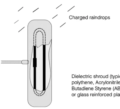
Precipitation static noise, caused by the exchange of static charges between raindrops and the antenna system, is a significant source of noise at frequencies below 150 MHz. It may be controlled by the fitting of insulating shrouds to antenna elements (see Annex C).
Ambient RF noise includes atmospheric, sky noise and man made electrical noise. In general this is beyond the control of the site operator (see Annex D).
On a remote green field site it may be possible to operate receivers in the VHF band at levels below - 110 dBm. However in a more realistic situation the minimum usable signal will be typically - 107 dBm.
5
Installation recommendations
5.1 Support structure and mechanical considerations
During the design and construction of support structures the following processes will need to be considered. For each of these processes compliance with the relevant National Standards should be achieved:
a) design of structural components; b) hot dip galvanising of steel components; c) spin galvanising of steel threads;
d) use of lock nuts, spring washers and other locking devices; e) anodising of aluminium components;
f) use of protective paints.
NOTE: The anodising on aluminium is likely to insulate the components and thus produce difficulties in terms of earthing and conductivity of the structure.
5.1.1 Structural integrity
The structural integrity of the mast or tower must be established by a competent structural engineer, the analysis must include the loads imposed by each antenna system.
5.1.2 Wind loading
The structural design should take into account the wind loading of all the components on the structure, e.g. antennas, feeders and associated hardware. Twist and tilt limitations for parabolic antennas may also have a bearing on design or reinforcement.
The design or selection of a suitable support must be by qualified structural engineers. The design of new structures should where possible take into account the probability of future development.
5.1.3 Protective coatings
The cutting or drilling of protective coated items should not be permitted during installation. On the occasions when cutting or drilling is unavoidable, consideration should be given to possible structural weakening, and the affected areas must be treated with a recommended protective coating. The painting of structures should be considered as an essential part of the post installation programme. A well defined schedule of time scale and of the exact process should form part of the design of the structure and must be implemented rigorously.
In the case of a galvanised structure there will be a recommended period after which a paint process should be applied.
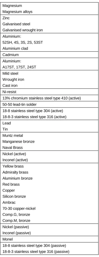
5.1.4 Use of dissimilar metals
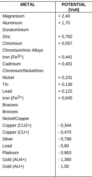
It should be carefully noted that wherever possible all metals used in contact with each other shall be in the yellow metal series, i.e. copper, brass, silver, nickel, or gold. The iron and steel part of the metals table should be avoided at all times as their oxides form nonlinear junctions and can cause intermodulation. The ideal combinations are silver/brass to copper using nickel plated nuts and bolts.
Structure design must take particular account of corrosion between dissimilar metals: electrolytic contact potentials between metals in contact in outdoor exposure must be less than 0,25 V, and in indoor situations should be less than 0,50 V. Annex E gives further information on the position of metals in the galvanic series and the potential differences that will exist.
5.2 Equipment room
There are several fundamental requirements for equipment rooms on radio sites which must be given full attention prior to the commissioning of the site. These are as follows:
a) the construction of the installation must provide security against vandalism and casual attack by intruders;
b) if services are to be provided on the site which warrant a high degree of security, then alarm systems must be fitted;
c) the cables in and out of the equipment room must be hidden or protected in such a way that they cannot be easily damaged;
d) the areas within the equipment room shall be divided off to allow access to individual parties as dictated by the requirements of the site;
e) that a separate area is provided for the common services facility, e.g. mains power supply, filter multicouplers and incoming feeder cable assemblies;
f) that heating and lighting be provided of a standard suitable for the environmental requirements of the site;
NOTE: The above criteria shall be judged when taking into account the climatic, access and future development conditions pertaining to each individual site. For some locations, e.g. mountain tops, it may not be possible to visit with normal vehicles during severe winter conditions. It will be necessary to provide standby and auxiliary mains power supplies for many sites where overhead power lines are provided.
5.2.1 Equipment arrangements
The equipment layouts given in Annex F are based on the assumption that a choice of position for various items within the equipment room can be achieved.
Often, however, equipment rooms are already disposed in certain aspects, e.g. the power supply arrangements and emergency batteries may already be installed and occupy a critical position adjacent to the door.
There are some fundamental rules that should apply wherever possible and these are as follows:
a) the filter couplers and associated signal distribution systems should be located in a separate area whenever possible and locked away from the transmitter and receiver equipment. This is to ensure that the filter parameters are not adjusted or interfered with by those who are not responsible for the filter performance;
b) whenever batteries or emergency supplies are involved, these should ideally be housed in a separate cubicle and ventilated to the outside atmosphere. This is to ensure that no explosive gases or corrosive fumes are present within the equipment room;
c) each frequency band will have its own cable feed and associated harness and therefore it is logical to present all the equipment in that band with adjacent racks and convenient to the cable tray;
d) it is always advisable to keep receivers and transmitters as far apart as possible and this can be arranged in separate racks within the frequency band and its associated area;
e) in some countries the common band allocations may be quite different from those shown in the diagrams given in Annex F and therefore can be interpreted separately for that country.
5.2.2 Environment
Consideration should be given to ensuring that the equipment room is kept at an ambient condition which never allows the temperature to fall below the dew point and which keeps within the specified temperature range of the equipment, or at an acceptable working temperature for personnel.
It may be necessary to provide heating, ventilation or cooling to achieve this condition. Precautions may be necessary to exclude pests and vermin from the equipment room.
5.3 Electrical supply, protection and lightning protection 5.3.1 Electrical supplies
The majority of sites will have ac power provided by the local Electricity Supply Authority. It is essential to arrange sufficiently large capacity for future expansion, and wherever possible a sub-division of the input circuits should be provided separately for each user function. This ensures that individual fuses or trips protecting sub-sections of the site installation cannot interrupt the supply of other users.
In many instances standby power supplies will be required and this should be based on the requirement of the service.
There are an increasing number of sites where dc supplies, in the form of large capacity batteries, are used to power equipment and these batteries are charged continuously by means of "float charge" systems. This has the dual advantage of automatic standby and "no-break" characteristics.
5.3.2 Lightning effects, protection and responsibilities
Radio sites can be particularly prone to lightning strikes by virtue of their normally exposed locations and the presence of relatively tall antenna support structures.
The effects of strikes on a site could comprise any or all of the following: a) death or injury to personnel;
b) damage to equipment, or loss of service; c) damage to buildings and structures; d) loss or corruption of stored data.
It is not possible to provide and guarantee complete protection from these dangers. However, they can be considerably reduced by careful attention to earthing, protection devices and the layout of the site itself. Understandably, site owners and users will be concerned with the protection of equipment to maintain the integrity of systems. However this concern must go alongside the prime consideration which is the safety of personnel.
Reference should also be made to various relevant publications. Where any site owner or site user is in doubt about the protection requirements for a particular location, the appropriate authority should be consulted.
The aims of any protection arrangements should be to provide a suitable path to earth for the lightning current, to ensure adequate bonding between structures, all metalwork on the site and the site common earthing system in order to reduce the side flashing, and to attempt to prevent the entry of flashes or surges into buildings.
Connections to site earthing systems (where corrosion may be unavoidable) should be made by means of a sacrificial anode of a material compatible with the structure being earthed.
All underground clamps on site earthing arrangements should be suitably protected by the use of non reactive, non setting pastes and tapes.
The resistance to earth should be kept to a minimum and a value of less than 10 Ω is recommended. The important feature is that the system should ideally be equipotential across the whole site.
Reference should generally be made to the appropriate National Standards for the protection of structures against lightning.
Certain authorities and service providers have their own particular practices which may have to be followed where applicable.
Arrangements will vary considerably from very simple sites to complicated sites with a multiplicity of buildings, antenna support structures and associated plant, and may involve integration with existing systems. Such systems may require upgrading.
Down conductors, bonding interconnections, earth rings and radial tapes should be of uninsulated solid copper tape of minimum cross sectional area 60 mm2 with all connection clamps and supports protected by non reactive paste or tape (aluminium conductors may be acceptable).
Where the tape may be subject to chemical attack, e.g. when in close proximity to concrete, it should be protected by the use of non reactive paste or similar.
Protected test points should be included if appropriate and sacrificial earth lugs should be clearly marked and easily accessible for periodic inspection and replacement if necessary.
5.3.3 Earthing of antenna support structures
A structure will generally act as its own lightning conductor and will not therefore require a conducting tape from the apex to its base. A lightning finial may be required to extend the zone of protection to protect equipment mounted on the top of the structure. The finial should extend to at least 1 metre above the highest equipment.
Ground mounted support structures should be connected at their base to an earth ring arrangement. This is normally by means of an anode usually in the form of a lug. Towers may require a connection from each leg. Replacement of sacrificial anodes should be part of the site maintenance programme.
An earth ring may consist of copper tape with driven earth electrodes or radial tapes round the base of the structure as close to it as possible, buried to a depth of approximately 0,60 metre where soil conditions allow. The earth rings should be connected to the main building earth by the most direct route, buried as appropriate.
Roof mounted structures should be connected to the main building earth by the most direct route using sacrificial anodes and copper tapes as appropriate.
Mast guy wires should be directly bonded at their lowest point to a suitable earth electrode or connected to the site earth by the most direct route.
5.3.4 Earthing of antennas, feeders and associated plant
All antenna feeders should be bonded to the tower at the upper and lower ends and earthed at the point of entry into the building (see Annex G). Weatherproof earthing kits are available from antenna manufacturers. Fast acting gas filled surge arrestors can be used on some systems and may provide additional equipment protection, providing that VSWR degradation is acceptable.
All gantries, fuel tanks, pipes above and below ground, fences and other metalwork within 3 metres of the support structure or building should be bonded to the earthing system by the most direct route using copper tape, buried where appropriate. This should include any reinforcing rods in foundations which are not already bonded to earth.
Ideally an earth ring should surround the building and be connected to the individual earths associated with the feeder entry, antenna support structure, building lightning conductor, equipment room, mains supply and other facilities. Each connection should be made by the most direct route to minimise interaction between the different earthing functions.
The earth ring should consist of copper tape with electrodes or radial tapes, buried to a depth of 0,60 metre and at a distance from the building preferably not exceeding 1,00 metre.
Buildings may require lightning air terminals (finials) where they are not within the zone of another protected structure.
5.4 Antennas and feeders 5.4.1 Choice of antenna type
The principle which governs the choice and siting of transmitting antennas is that only the minimum necessary erp must be radiated in each desired azimuth direction.
Omnidirectional antennas should be used only when necessary for the service requirements. The simplest examples of this class of antenna are top-mounted end-fed and coaxial dipoles, monopoles and collinear arrays. When omnidirectional characteristics are required of a side mounted array, a number of antenna elements must be placed around the supporting structures.
There are many satisfactory types of directional antennas; common examples are yagi arrays, corner reflector antennas and panel antennas.
Many antennas in common use fall between the omnidirectional and directional types described. They include simple dipoles side-mounted from support structures. Many of these antennas have ill-defined radiation pattern performance and are likely to give rise to radiation of intermodulation product frequencies originating from currents excited in the supporting structure. Their use is not recommended for multi-frequency applications.
5.4.2 Antenna specification
The following parameters must all be specified when procuring or selecting antennas. Electrical:
a) Gain
Specified either in dB relative to an isotropic radiator (dBi) or a half-wave dipole (dBd).
b) VSWR
Specify the maximum value compatible with the system being considered. c) Radiation pattern
Specify the beamwidth in the azimuth and elevation planes, together with any necessary restrictions on side or rearlobe levels.
d) Balance ratio
This parameter defines the effectiveness of the balun fitted to balanced driven elements and consequently the acceptable level of currents on the outside surface of the feeder cable. A value of 20 dB should be considered as a minimum.
e) Input power
For combined transmitter outputs specify both the mean, and peak powers. f) Intermodulation performance
The following specifications are desirable:
- for single frequency transmit and receiving applications:
- 100 dBc.
- for multiple frequency transmission:
- 130 dBc.
- for multiple frequency transmission and reception on a single antenna:
- 143 dBc.
The more severe specification will be met using all-welded construction and exceptional care in the encapsulation of antenna terminal arrangement.
g) Bandwidth
Specify the frequency band over which the antenna is to be used, over which all the parameters specified must be met. The practice of regarding the VSWR bandwidth as indicating the usable frequency band is unsound.
Mechanical:
a) structural design of antennas and supports must comply with relevant National Standards; b) electrolytic contact potentials between dissimilar metals must be less than 0,25 V even for
encapsulated assemblies;
c) conformity to a chosen environmental test specification.
5.4.3 Location of antennas
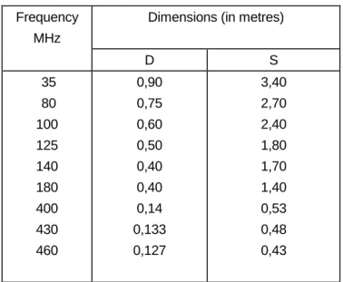
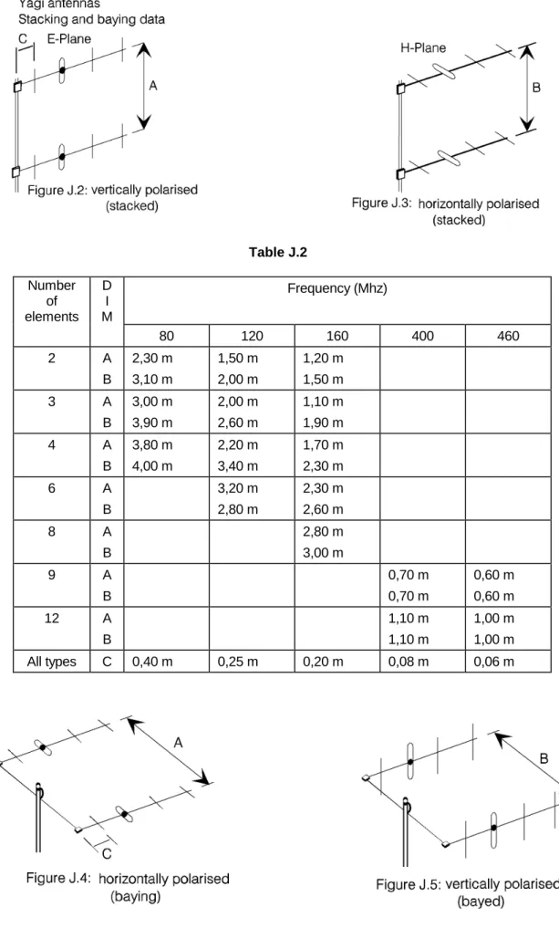
When determining the mounting positions for antennas each antenna must be mounted in a manner which does not impair its performance (see Annexes H and J). The spacing between antennas must be chosen to provide sufficient isolation to allow system intermodulation product targets to be met (see Annex K).
5.4.4 Radiation pattern
As a general rule, the less directional the radiation pattern of an antenna, the greater the influence the mounting environment has on the pattern.
Highly directional antennas such as paraboloidal dishes and antennas with large mesh reflectors have high front/back ratio and may be regarded as largely independent of what lies behind them. Antennas of moderate front/back ratio such as yagis must be mounted with their rear elements at least one wavelength from the supporting tower if optimum performance is to be achieved.
Nominally omnidirectional antennas (dipoles, stacked dipole and collinear arrays) will only achieve genuine omnidirectional performance when mounted on top of the supporting structure. When side mounted, large currents flow in the supporting structure, causing distortion of the omnidirectional pattern and the probability of intermodulation product radiation due to non-linear joints between structure members or mast sections. In practice omnidirectional azimuth patterns can be obtained only by side mounting several antennas (usually 3 or 4) firing in equispaced radial directions. Radiation patterns may be most accurately predicted when the individual units of the antenna have a large front/back ratio. As such antennas are very expensive, their use is most attractive when a number of services can be multiplexed onto a single broadband antenna system.
5.4.5 Gain
The modification of the radiation pattern of an antenna, referred to above, also implies a change in its directivity and hence its gain. In general an antenna will lose forward gain when mounted too close to the supporting tower since the side and rear lobes will be increased. These changes result in reduced forward range and reduced protection against co-channel interference.
5.4.6 Cross-polar performance
The cross-polar performance of base station antennas for the mobile service has in the past been non-critical, as all stations used vertical polarisation. An important change has taken place with the opening of services in Band III (174 - 225 MHz) to the mobile radio service in some European countries as polarisation protection is an important parameter in ensuring low interference levels caused to (and by) continuing overseas television transmissions in that band. Similar consideration will also apply in Band I (41,50 - 67 MHz).
In bands used for fixed services the cross-polar protection provided by link antennas is an important factor in frequency planning and management. The geographical separation between stations using the same
frequency can be reduced when orthogonal polarisation is used. The Cross-Polar Discrimination (CPD) achieved by a practical antenna under test range conditions will lie between 20 dB, for a simple yagi or dipole of orthodox construction, and 40 dB, for a paraboloidal reflector illuminated by a well designed feed horn. The significance of the path to CPD must be considered.
Two commonly seen faults degrade the CPD of an installed antenna:
a) if an antenna is installed in such a position that currents are induced into members of the supporting structure, these currents, flowing in arbitrary directions, will couple energy from the plane in which it was radiated into the orthogonal plane. This is a particular hazard for installations of yagi and similar antennas of moderate or low directivity;
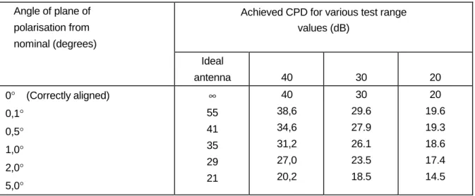
b) failure to erect antennas with the plane of polarisation aligned exactly in the required direction produces a field component in the orthogonal plane. The CPD of an ideal linearly polarised antenna falls as misalignment increases, as shown in Annex L.
5.4.7 Voltage standing wave ratio
For a transmission line to deliver RF power efficiently to a load it is necessary for the load to behave as a pure resistance equal in value to the characteristic impedance of the line. Impedance discontinuities cause RF energy to be reflected back from the discontinuity towards the input of the line.
Reflections upset the uniform distribution of RF voltage and current on the line. Standing waves are established which cause voltage and current maxima and minima to exist at intervals along the length of the line. In severe cases Standing Waves may cause transmitter shutdown or the failure of system components. There are two major causes of increased VSWR when an antenna system is mounted for use. In the VHF band, where antennas of low or moderate directivity are used, the proximity of structural or mounting components will change the antenna VSWR; this change will be of most significance when a very low antenna VSWR is needed. Above VHF (where more directive antennas are generally used) the main cause of degradation is reflection from connectors and from discontinuities in the line itself.
It should be noted that the attenuation of the antenna feeder has the effect of reducing the VSWR seen by the transmitter.
When designing or working on equipment at radio sites it is frequently necessary to calculate the reflection performance or matching condition of components in the RF system. It is often necessary for example to predict the matching condition at a certain point from specification or measurement data obtained elsewhere in the system.
Reflection calculations may be used to determine the worst-case VSWR which may occur with specified components, or to determine the component limits when the overall system performance is already determined.
Traditionally VSWR has been in common use to express the reflection performance of RF systems. In certain situations however, return loss and voltage reflection coefficient prove more useful.
Formulae for conversion between VSWR, return loss and voltage reflection coefficient and methods of calculation for reflection performance are dealt with in Annex M.
5.4.8 Wind vibration
All antennas, mounting steelwork, feeders and ancillary equipment should be securely clamped to protect feeders and other semi flexible items from damage by vibration throughout the projected life of the installation.
Manufacturers' recommended feeder clamp spacings should be observed, with particular attention to exposed areas and transitions from antenna to tower, tower to gantries and gantries into buildings. Feeders should not be laid loose on gantries. Where necessary additional protection should be provided.
5.4.9 Degradation of antenna performance
It is important to appreciate that the performance of an antenna is very dependent on the environment in which it is mounted. This is particularly true of many antenna types commonly used in the VHF and UHF bands. The data quoted by manufacturers will generally relate to parameters measured on a test-range in which the antenna is erected clear of all obstructions, using the optimum mounting arrangement. Such an environment will not normally apply at a typical user's installation, and inferior performance may result unless particular care is taken.
Annex E shows a number of common configurations and indicates their relative merits.
5.4.10 Cables, cable routes and connectors
It is recommended that wherever possible, solid, semi-rigid or double-screened cables should be used for all RF connections. This is to ensure maximum screening between adjacent cables and feeders and to reduce coupling between equipments. The use of single screened cable (e.g. UR67, UR43, RG58) should be avoided wherever possible and in particular, in cable runs where several of these conductors are brought close together.
The direct and shortest route is always the best for minimum radiation and minimum insertion loss. However it is important that transmitter cables and receiver cables should be installed as far apart as possible. It is advisable that when they cross they should cross at right angles. Cable trays carrying transmitter cables should not also be used to carry receiver path cables and it is best if cables are insulated from each other at all times. It is normal to use cables with insulated outer jackets and the only points at which earth straps and earth bonding should be employed are those specifically chosen for the purpose.
It is often convenient to break down very large feeder cables to a more convenient size and there is a tendency to place connectors just inside the equipment room when reducing the main incoming feeder to a more manageable size. It is best, however, to take the main feeder as close as possible to the equipment to which it is to be connected before interrupting its outer conductor.
The only exception to this rule is to provide an earth connection for lightning conductor purposes and this should be carried out by means of an external clamp on the outer copper conductor and this should be taken via the most direct route.
Incoming feeders must not be interconnected by a "patch panel", traditionally used in the past. The "patch panel" is a source of earth current coupling and intermodulation and should be avoided.
It is also recommended that high quality connectors be used and a minimum standard would be type N, preferably with a silver-plated finish. The use of such connectors produces maximum screening effect and gives the best RF connection between the various components of the system. Connectors such as type "UHF" have been the cause of many problems and their use should be avoided. All connectors must be fitted in conformity with manufacturers' instructions to ensure proper sealing and electrical uniformity.
5.4.11 Feeder identification, terminations and earthing
Feeder cables should be uniquely and permanen