Adaptive Load Control of Service Oriented
Architecture Server
I. Atanasov
Key Words: Service Oriented Architecture;application server; admission control; load balancing.
Abstract: This paper presents an adaptive algorithm for improving the utilization of application server for open access to network functions. This type of application server deals with differently prioritized mes-sage flows from both 3rd party applications and the network. The application server model applies admission control and distributed processing and the control strategy takes into account the different activity patterns of the service providers.
1. Introduction
The evolved packet mobile networks feature convergence between IT applications and telecommunication services. One of the main convergence enablers is the open service access. The open service access allows 3rd party applications to be able to
use network capabilities while being outside the telecom operator’s domain. A technology that provides open access to network functions is Parlay X Web Services [1]. The access is provided through application programming interfaces (APIs) which hide for application developers the underlying network specifics and protocol complexity. Parlay X APIs are defined with the intention of enabling the creation of a SOA (Service Oriented Architecture) solution.
A common problem in the deployment of SOA applications is server performance and utilization. SOA grids can be used to break the convention of stateless-only services for scalability and high availability by allowing dialogs to occur across multiple service requests as it is in [2]. Due to the great advantages that SOA offers to its adopters in almost all fields, many studies have tried to leverage it in grid computing. These studies have fo-cused on enabling easy access and flexible management to underlying grid resources [3]. However, there are still chal-lenges for traditional applications of message-oriented middleware in order to achieve high levels of quality of service (QoS) when sharing data between services over an enterprise service bus. In [4], the authors present an analytical framework to derive the response time and service availability of client/server based SOA and P2P based SOA. The study presents the impact on the response time and service availability for varying load conditions and connectivity for both client/server and P2P SOA implemen-tation. The authors of [5] suggest SOA server virtualization driven by the goal of reducing the total number of physical servers in an organization by consolidating multiple applications on shared servers. The expected benefits include more efficient server utilization, and a decrease in greenhouse gas emissions. How-ever, SOA combined with server virtualization may increase risks such as saturation and service level agreement (SLA) violations. This paper presents an adaptive load control mechanism
for SOA servers which introduces a performance improvement and thus allows an increase of its utilization.
The Parlay X gateway is a special type of SOA server which has to make the conversion between APIs and control protocols in the network. It is engaged in processing different traffic types and the traffic majority for Parlay X Web Services like Third party call [6], Payment [7], and Audio call [8], consists of messages from Service Providers (SPs) which have contracted SLAs with the network operator. For Web services like Terminal location [9], Terminal status [10], Application-driven Quality of Service [11] the traffic includes also a great deal of notification mes-sages sent by the network.
The network operator that governs the Parlay X gateway has to sign a SLA, defining the QoS parameters, with every Parlay X service provider. The main tools in order to avoid congestion are the so called admission control mechanisms. In [12], the authors propose a load control mechanism aimed at supporting constraints imposed by the distributed Parlay X gateway archi-tecture. The mechanism uses preliminary defined threshold values in order to predict the load and to decide if the message should be accepted or rejected. The results in [13] treat load control for distributed web-based applications. The authors suggest a control algorithm that self-configures a dynamic constraint on the rate of incoming new sessions in order to guarantee the fulfilment of the quality requirements specified in service level agreement (SLA). In [14], a staged event-driven architecture is proposed which decomposes a complex, event-driven applica-tion into a set of stages connected by queues. The architecture avoids the high overhead associated with thread-based concurrency models, and decouples event and thread schedul-ing from application logic. The proxy-based overload control for web applications presented in [15] is based on measurements of metrics such as response time, throughput, and resource utilization. The authors of [16] present aload control mecha-nism of Parlay X application server, using the Leaky Bucket algorithm in order to control message flows based on estimation of the queue waiting time of a newly arriving message. In [17], the authors suggest an adaptive load control of Parlay X gateway which processes traffic generated by SPs and optimizes the gateway utilization. A model of Parlay X gateway which pro-cesses traffic generated both by SPs and by the network is presented in [18]. The model is used only for estimation of gateway utilization in terms of traffic shaping and does not apply adaptive control.
The idea in this paper is to go beyond utilization estimation as it is done in [18] and to apply dynamic admission control to traffic of different priorities. The suggested control strategy takes into account the ongoing application demands and thus influ-ences the Parlay X gateway utilization.
The structure of this paper is as follows. Section 2 is dedicated to the Parlay X application server environment and
architecture description. Admission control, traffic filtering and load balancing are mathematically formalized in Section 3. The Parlay X gateway utilization function and the adaptive strategy are defined in Section 4. Section 5 presents some simulation re-sults. Conclusions are presented in the last section.
2. Model of SOA Server Structure
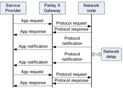
The environment of the Parlay X gateway consists of Ser-vice Providers (SPs) that host applications and a node on the network. Using Parlay X APIs, SPs generate requests to be served by the network. The Parlay X gateway communicates with the network node by a control protocol. The control protocol transfers request and answer messages and any notifications from the network.
2.1. Traffic Template
A typical message exchange template includes application generated requests for initiation and termination of its interest in observing certain conditions in the network. The initiation is depicted in figure 1 by the first four messages and the termina-tion is consisted of the last four. The notificatermina-tion phase might be periodic, on-demand or hybrid.
For example, the “Application-driven Quality of Service” (ADQ) is a Parlay X Web service that allows 3rd party applications
to dynamically control the QoS available on the user connection. During the first phase, the application sets temporary new QoS features to an active user session and subscribes to notifications about QoS events. During the notification phase, any QoS events related to the user session are reported. The application may decide to terminate the user session or to terminate the sub-scription for QoS events.
Another example is the “Terminal location” Web Service which allows the application to receive notifications when the user location is changed.
The model in [12] concerns the “Third Party call” Web Service and the respective message exchange initiated by SPs only. For the purposes of our case this is not enough because
the incoming traffic is generated by Parlay X applications hosted by SPs, and by the network. The case we investigate is when there are messages of three different classes and respectively three different priorities. These are: messages from applications related to the initial phase (start messages) with lowest priority, notification messages from the network with normal priority and messages from applications related to the third phase (stop messages) with high priority.
2.2. Abstraction Model of the SOA Server
A SLA driven architecture is considered. Each SP might include several applications but as the SLAs are agreed to between the SPs and the network operator that owns the Parlay X gateway, the number of applications is not important.
The SLA between SP and network operator defines con-straints that have to be fulfilled. The concon-straints include the peak and average number of different application requests and net-work notifications that should be accepted per time unit, and the maximum delay between application request and response.
To be able to fulfil the restrictions imposed by the network operator and to avoid congestion, the Parlay X gateway imple-ments an Admission Control/Load Balancing mechanism. The Admission Control (AC) is used to protect the Parlay X gateway when there is not enough capacity to process all requests. In this case, some of the requests are rejected according to the well-known algorithm of Token Bucket (TB), as an example. Usually the Parlay X gateway has several processing nodes (converters). In a distributed environment the traffic that has to be served is split between processing nodes equally. Different algorithms for load balancing (LB) are developed.
The Parlay X gateway system is built of n SPs and m
converters as shown in figure 2.
The admission control rejects the non-conforming mes-sages being either SP’s requests or network notifications. If a message passes the access control, it is forwarded to the appropriately selected converter over the message bus (MB1). The appropriate selection is based on load balancing that dis-tributes load uniformly between converters. Each converter
trans-Service Provider Parlay X Gateway Network node Network delay Protocol request Protocol response App request App response Protocol notification App notification Protocol notification App notification Protocol request Protocol response App request App response
lates application requests into protocol messages, and protocol notifications into application requests. We assume that all
con-verters have the same capacity. Load balancing is based on the Round Robin algorithm because of its robustness.
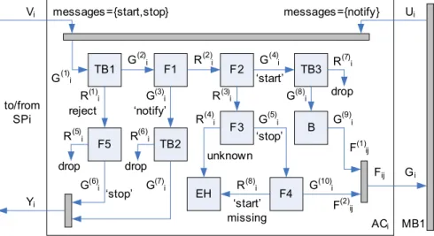
The abstract model of the i-th SP is shown in figure 3, where Vi(tk) is the number of start and stop messages within the interval [tk-1, tk]. To protect the Parlay X gateway from overload, a rough admission control is used (TB1). If a message is rejected, filter F5 passes only rejected stop messages. If a stop message is rejected, the application has to be informed. The filter F1 passes notify messages which are forwarded to the TB2 which prevents the Parlay X gateway from overloading caused by network initiated notifications. The conforming notifications are forwarded to the application. If the accepted message is not a notification message it is filtered by F2 which passes start messages. The start messages are forwarded to the TB3 which controls that the constraint of accepted number of start mes-sages is fulfilled. The accepted start message is forwarded for load balancing.
If an accepted message is neither a notification nor a start message, it is forwarded to filter F3. In the case of a stop
message filter F4 is used to correlate the stop message with the corresponding start message.
The model of the j-thconverter is shown in figure 4 where Zi(tk) is the number of all notifications sent by the network within the interval [tk-1, tk]. Parlay X gateway Service provider 1 Service Provider 2 Service Provider n Network Access Controller 1 Access Controller 2 Access Controller n Converter 1 Converter 2 Converter m MB1 MB2
Figure 2. Distributed model of Parlay X Gateway structure
MB1 MB2 Q PU messages= {notify} messages = {start,stop} messages = {notify’} converterj messages = {start’,stop’} Hj Zj G(11)j G(12)j R(9) j Fj Uji Uj drop
Figure 4. Model of j-th converter
ACi MB1 TB1 F1 F2 F3 TB2 TB3 B reject ‘stop’ ‘start’ ‘notify’ EH unknown
messages ={start,stop} messages ={notify}
F5 ‘stop’ drop drop drop to/from SPi Vi Ui G(1)i G(2)i G(3) i G(4)i G(5)i G(6) i G(7)i G(8) i G(9)i F(1)ij R(1) i R(2)i R(3) i R(4)i R(5)i R(6)i R(7)i F4 G (10) i F(2)ij R(8) i ‘start’ missing Fij Gi Yi
Each of the converters is modelled as a single FIFO buffer
(Q) with limited size. The message is fetched out of the queue,
translated by the processing unit (PU) and forwarded either to
the network or to the application.
3. Component Model
This section presents formal descriptions of mechanisms used for admission control, message filtering and load balancing.
3.1. Token Bucket Model
The message traffic is observed at regular time intervals
[tk-1, tk]. The token bucket model TB(T,ρ,μ) is characterized by
volume T, rate ρ and level μ. The equation (1) represents the
initial token level (1) μ(t0)=T.
The token level at the end of the time interval [tk-1, tk] is
(2) μ(tk) = μ(tk-1) + A(tk) – G(tk)
where A(tk) is the amount of tokens arrived within [tk-1, tk], and G(tk) is the amount of tokens given in [tk-1, tk].
By N(tk) it is denoted the number of messages arrived to
the TB within [tk-1, tk]. Then
(3) A(tk) = min(T – μ(tk-1), ρ.(tk – tk-1))
(4) G(tk) = min(μ(tk-1) + A(tk), N(tk)).
The amount of rejected messages is (5) R(tk) = N(tk) – G(tk).
3.2. Message Filter Model
By C = {cj} it is denoted the set of all classes of
mes-sages defined, K is the number of message classes, and cjis
the j-th class of messages. Then the classifier function that
checks whether given message m belongs to class cj is
pre-sented by
(6) d(m, cj) = j.I(m ∈cj)
where I is an indicator function i.e. I(s)=1 if s istrue, and I(s)=0
otherwise. The number of messages belonging to class cjand
passed by a filter is
(7) F(cj, N(tk))= I(N(tk) >0).
Σ
I (j = d(mn∈cj)). The number of messages rejected by the filter is (8) R(cj, N(tk)) = N(tk) – F(cj, N(tk)) .3.3. Load Balancer Model
The load balancer model LB(σ,M) is characterized by its
internal state σ and the set of destinations M that LB is going
to distribute the load to. Then the LB initial state is
σ(t0) = random(m) where m is the power of set M and
random(m) is uniform distribution between 0 ... m-1.
If N(tk) = 0 then σ(tk) = σ(tk-1) and the number of
messages distributed to the j-th element of M is F
i(tk) = 0. If N(tk) > 0 then the index of the element of M that is going to
be the destination for the n-th message within [t
k-1, tk] is
(9) bn = (1 + σ(tk-1) + n)mod m, n = 1...N(tk).
The number of messages addressed to the j-th destination
within the period [tk-1, tk] becomes
(10) Fj(tk) =
Σ
I (bn = j) .Combining the above cases N(tk) = 0 and N(tk) > 0 gives
the total number of messages balanced toward j-th destination
(11) Fj(tk) = I(N(tk) > 0).
Σ
I (bn = j).3.4. Converter Model
Let any message of class cjrequire w(j) amount of service
provided by the converter it is dispatched to. Then the state of the buffer can be recurrently presented as
(12) q(tk) = q(tk-1) – G(tk) + A(tk)
where G(tk) is the amount of messages fetched out of the buffer
and A(tk) is the amount of the placed ones and q(t0)= 0. Having
ζ of the total converter’s capacity dedicated to message
conver-sion and a hard limit set on the length of the buffer, denoted by Qmax, it is easy to define for G(tk) and A(tk) the following
(13) G(tk) = I(q(tk-1) + N(tk) > 0) ×
max ζ . (tk – tk-1) ≥
Σ
Σ
w(j).I(q[l]∈c j)(14) A(tk) =min(N(tk), G(tk) + Qmax – q(tk-1)).
It is trivial to observe that the amount of losses caused by finite buffer in the converter within [tk-1, tk] is
(15) R(tk) = N(tk)- A(tk).
4. SOA Server Utilization Model
Using the Token Bucket model, Filter model and Load Balancer model as component models it becomes feasible to express all the message flows in the AS abstract model and more specifically between i-th AC and j-th Converter.
4.1. Utilization Function
The following notations are used:
• N– number of SPs, respectively AC;
• M – number of converters;
• ki – capacity of i-th access controller dedicated to
access control function;
• kj– capacity of j-th converter dedicated to conversion.
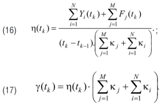
The gateway utilization and throughput in [tk-1, tk] are given
by equations (16) and (17) respectively n=1 N(tk) N(tk) n=1 n=1 N(tk) ⎧ ⎩ ⎫;⎭ m l=1j=1 m K
(16) . ). ( ) ( ) ( ) ( 1 1 1 1 1
M j N i i j k k N i M j k j k i k t t t F t Y t ; (17)(
)
(
)
.
1 1
M j N i i j k kt
t
4.2. Adaptive Control Strategy
In this section, a loss function is defined and a control policy that minimizes it is presented. The loss function for the network provider is given by
(18) ( ( ( ) .( )) ( ). 9( )), 1 8 4 ) ( 1 1 k j M j k j k p p i K k N i k i t R t t R t L
where K is the number of observed intervals.
The parameters {i, j i = 1... N, i = 1... M,} are
non-negative functions of time assigning relative weights given to various losses. The first parameter imposes a penalty on lost traffic at the admission control for the i-th TB and the second
parameter imposes a penalty on losses in the j-th converter. The
problem is to find a control policy that minimizes this function. By 2
i g
it is denoted the guaranteed rate of notification from the SLA between i-th SP and the network operator and as
it is fixed it doesn’t vary in time. The focus is set on the losses of notifications as far as the converters had spent part of their capacity to perform conversion. Thus the control policy is on the actual rate of tokens for the TB2s as follow:
(19) 2( ) 2( ) max( ( 1) 1( ),0). ( )( )( ) k i k i k i k i k k i k g k i t i t t t G t V tU tU t .
The left side of equation (19) presents the rate of tokens
that will be granted to i-th SP for the interval [t
k, tk+1] especially
for messages of notification type. The first component on the right side is the guaranteed rate of tokens from SLA, and the second component represents the part of available resources of
i-th access controller that are proportionally engaged with the
notifications flow of messages.
5. Simulation of SOA Server Behaviour
5.1. Simulation Parameters
The simulation is done on a simplified Parlay X model with three classes of messages and four converters. The parameters used are provided by a mobile operator. The capacity of the gateway is 800 requests per second which is equally distributed between the converters. The behaviour of each SP is modelled by Markov Modulated Poisson Process (MMPP). New application requests are generated according to four-state MMPP. Changes between different states are uniformly distributed and occurred according to Poisson process with mean 4s. The time intervals between start messages generated by each SP are exponentially distributed as the arrival process in the context of web services [16] with mean 150 s. During an application session the time intervals between event messages generated by the network are exponentially distributed with mean 50 s. The SPs traffic is po-liced by access controllers whose conforming outputs are mul-tiplexed between 4 converters. The token rate is equal to the guaranteed rate and the bucket size is determined by the peak rate. Initially, i(t0)= T0, qi(t0)= 0. The length of the interval for observation [tk-tk-1] is set to 100 ms. The processing time for a single request/ response in a converter is 5 ms.
The aim of this simulation is to evaluate the Parlay X gateway utilization by setting different values of guaranteed rates and fixed peak rates. The guaranteed rates for a given SP define the constraints for preventing the Parlay X gateway from over-loading (GR1), for the rate of event messages (GR2), and for the rate of start messages (GR3). The processing capacity of the Parlay X Gateway must be distributed between different types of messages, where the peak rate (PR1) must be spread between notification (PR2), start (PR3), and stop messages.
5.2. Results and Discussion
The simulation is run in a space of Ser-vice Level Agreements (SLAs) where each one is consisted of (PRi, GRi) for every TBi of given access controller. Figure 5 summarizes the outcome of the simulation. The Parlay X gate-way utilization is evaluated as a function of the number of SPs and guaranteed rates. The guar-anteed rates of messages per second as as-signed by the mobile operator are included into four different SLAs. The values of peak rates
PR1 =100, PR2 =60, PR3 =20 are limited by the converter capacity. There are no statistics about frequencies of different messages but based upon practice-driven predictions we estimate
Parlay X Gateway Utilization versus Number of Providers and Guaranteed Rates
0 0,2 0,4 0,6 0,8 1 1,2 8 9 10 11 12 13 14 15 16 17 18 19 20 21 22 23 24
Number of Service Providers
U tiliz at io n SLA1 {90,54,18} SLA2 {80,48,16} SLA3 {60,36,12} SLA4 {40,24,8}
that there will be several notifications per session from the network.
The simulation results show that the utilization depends both on the number of SPs and on the specific values of rates in SLAs. In the case when the network operator sets the conges-tion threshold value of 80%, it is most likely that the appropriate choice is to have 22 SPs applying second type or third type of SLA. Applying adaptive control leads to higher utilization than in the case without control. The average throughput gain is about 8%.
6. Conclusion
This paper presents an evaluation model of load of a Parlay X gateway with distributed architecture. The model considers processing of messages of different classes and dif-ferent priorities. An adaptive control strategy that improves the SOA application server utilization is suggested. It applies dynamic admission control based on application demands.
The simulation results can be used for setting values of quality of service parameters agreed to with the network operator.
Further extension of the case study will involve addition of limiting inequality in order to constrain the utilization at the near-congestion area.
Acknowledgement
This research is conducted within the framework of project 122pd0007-7/2012 “Adaptive Methods for Resource Manage-ment in Evolved Packet Networks” at Research and DevelopManage-ment Sector, Technical University of Sofia.
References
1. Darvishan, A., H. Yeganeh, K. Bamasian, H. Ahmadian. OSA Parlay X Gateway Architecture for 3rd Party Operators Participation in Next Gen-eration Networks, ICACT’10, 2010, 75-80.
2. Chappell, D., D. Berry. SOA - Ready for Primetime: The
Next-Generation, Grid-Enabled Service-Oriented Architecture. - SOA Magazine,
Issue X, 2007, http://www.soamag.com/I10 /0907-1.php.
3. Riad, A., A. Hassan, Q. Hassan. Design of SOA-based Grid Computing
with Enterprise Service Bus. - International Journal on Advances in
Information Sciences and Service Sciences, 2, 2010, No. 1, 71-82. 4. De, P., P. Chodhury, S. Choudhury. A Framework for Performance Analysis of Client/Server Based SOA and P2P SOA, Proc. of ICCNT’2010, 2010 ,79-83.
5. Brebner, P.; L. O’Brien, J. Gray. Performance Modelling Power Con-sumption and Carbon Emissions for Server Virtualization of Service Oriented Architectures (SOAs). Proc. of EDOCW’2009, 2009, 92-99. 6. 3GPP TS 29.199-2 Part 2: Third Party Call, Release 9, 2009. 7. 3GPP TS 29.199-6 Part 6: Payment, Release 9, 2009. 8. 3GPP TS 29.199-11 Part 11: Audio Call, Release 9, 2009. 9. 3GPP TS 29.199-9 Part 9: Terminal Location, Release 9, 2009. 10. 3GPP TS 29.199-8 Part 8: Terminal Status, Release 9, 2009. 11. 3GPP TS 29.199-17 Part 17: “Application-driven Quality of Service (QoS) , Release 9, 2009.
12. Anderson, J., M. Kihl, D. Sobirk. Overload Control of a Parlay X Application Server, Proc. of SPECTS’04, 2004, 821-828.
13. Bartolini, N., G. Bongiovanni, S. Silvestri. Self-through Self-learning:
Overload Control for Distributed Web Systems. - Computer Networks,
53, 2009, 727-743.
14. Mathur, V., S. Dhopeshwarkar, V. Apte. MASTH Proxy: An Extensible Platform for Web Overload Control, 2009, http://www2009.org/ pro-ceedings/pdf/p1113.pdf.
15. Zhang, Qi-zhi. On Overload Control of Parlay Application Server in
Next Generation Network. - Journal of China Universities of Posts and
Telecommunications, 15, 2008, issue 1, 43-47.
16. Muscariello, M., M. Mellia, M. Meo, M. Marsan, R. Lo Cigno. Markov Models of Internet Traffic and a New Hierarchical MMPP Model.
-Computer Communications, 28, 2005, Issue 16, 1835-1851. 17. Atanasov, I., D. Marinska, E. Pencheva. Load Evaluation Model of Parlay X Gateway. Proc. of IEEE International Conference TELSIKS’2011, Nish, Serbia, 1, 2011, 289-292.
18. Atanasov, I., D. Marinska, E. Pencheva. Open Service Access in Cross Layer Design, Proc. of International Workshop on Cross Layer Design IWCLD’2011, Rennes, France.
Manuscript received on 14.02.2012
Ivaylo Atanasov received M.S. degree in electron-ics from Technical University of Sofia, and PhD degree in communication networks. His current position is Associate Professor at Faculty of Tele-communications. His main research focus is de-velopment of open service platforms for next generation networks.
Contacts: Technical University of Sofia, Sofia, Bulgaria tel: 359 2 965 2050 e-mail: [email protected]