APPLICATION OF EXCEL IN THREE - PHASE CIRCUIT ANALYSIS
Darina ŠPALDONOVÁ, Milan GUZANDepartment of Theoretical Electrotechnics and Electrical Measurement, Faculty of Electrical Engineerig and Informatics, Technical University of Košice, Park Komenského 3, 043 89 Košice, Slovak Republic,
E-mail: [email protected] , tel. + 421 55 602 2578, E-mail: [email protected] , tel. +421 55 602 2706
SUMMARY
This paper illustrates the application of one component ofOFFICE package - Excel - in circuit theory and describes two special programs for the three-phase circuits in harmonic steady state analysis. In the first order it is shown how to access that the basic functions of Excel will work with complex numbers, further all two programs are described and illustrated. First of them is for the connection format of three-phase appliance Y analysis and the second for the appliance of connection format D analysis.Three-phase circuit with the appliance of connection format Yanalysismeans phase current computing,as well as the real, reactive and complex power transmitted by three-phase load and reactive and complex power on the appliance. Three-phase circuit with the appliance of connection format Danalysismeans phase and load current computing,the real, reactive and complex power transmitted by three-phase load and real, reactive and complex power on the appliance. Both these programs grant to draw the phasor diagram of voltage and current phasors as graphic representation of the results. The failure states (short connection or disconnection of some phase) analysis is also possible. These programs can be found on the http:// www.tuke.sk\fei-kteem/aei06/y.xls and http:// www.tuke.sk/fei-kteem/aei06/d.xls. Presented programs grant to do the full analysis of three-phase circuits. Our goal is to prepare studying materials for the course Theory of electrical engineering with included programs in Excel for graphical illustration of analysis results for the circuits with anharmonic sources, graphic illustration of analysis results for the simple circuits with pulse on the input, full computer processing of long distance line analysis including graphics illustration of results.
Keywords: theory of electrical engineering,three-phase circuit, three-phase load, three-phase appliance
1. INTRODUCTION
The restructuring of our university study brings the changes of contents as well as forms of study and methods of control the study results. This situation results in the requirement to prepare the new study materials. These materials are preparing in the electronic form and will be complete with some computing programs. For the easy availability of these materials we are using usual computer technique and software – operating system Windows and package OFFICE. Some kind of circuits are suitable for developing the general mathematic prescription for which is easy to make a computer program for solving inclusive of its graphic representation. The other kind of circuits is not suitable for such a general mathematic prescription, but graphic illustration of the results are also very useful. Till now developed computer programs for analysis of three-phase circuits with the appliance of connection format Y and connection format D. In this case we used one component of package Office – Excel.
2. THREE-PHASE CIRCUIT ANALYSIS
The three-phase circuit consists of three-phase source, three-phase load and three-phase appliance. The analysis of these circuits in harmonic steady state means in the first order phase and load currents calculation. These calculations were made in the complex area after the substitution the time behavior to phasor.
The three-phase appliance can be connected in the form of Y or D (Fig.1). This paper deals with both appliance connections.
In connection format Y are phase currents identical with lead currents and for their phasors is
1 ( 1 N
)
1 I = U −U Y , 2 ( 2 N) 2 I = U −U Y , (1) 3 ( 3 N) 3 I = U −U Y . 12 U 23 U 31Z
U V W 23 Z 12 Z 31 I 23 I 12 I 31 U 1 I 2 I 3 I b) N U V N I 1 Z 2 Z 3 Z N Z N U 1 U 2 U 3 U a) I1 2 I 3 I Wwhere 1 1 2 2 3 3 N 1 2 3 N UY U Y U Y U Y Y Y Y + + = + + + ; (2) 1, , 2 3
U U U is system of phase voltages and for the balanced three-phase source is defined like
0 j 1 f e V U =U ϕ , 0 j( 120°) 2 f e V U =U ϕ − , (3) 0 j( 120°) 3 f e V U =U ϕ + ; 1
Y, Y2 and Y3 are admittances of 1., 2. and 3. phase of connection format Y appliance;
N
Y is admittance of neutral wire.
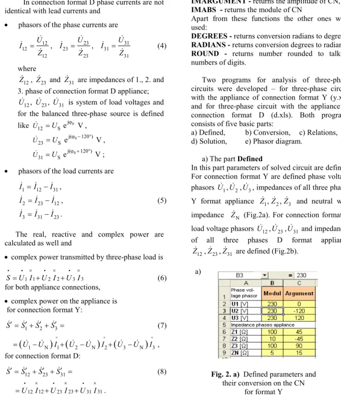
In connection format D phase currents are not identical with lead currents and
• phasors of the phase currents are
12 12 12 U I Z = , 23 23 23 U I Z = , 31 31 31 U I Z = (4) where 12
Z , Z23 and Z31 are impedances of 1., 2. and 3. phase of connection format D appliance;
12, , 23 31
U U U is system of load voltages and for the balanced three-phase source is defined
like j 0 12 Se V U =U ϕ , 0 j( 120°) 23 S e V U =U ϕ − , 0 j( 120°) 31 Se V U =U ϕ + ;
• phasors of the load currents are
1 12 31 I =I −I , 2 23 12 I =I −I , (5) 3 31 23 I =I −I .
The real, reactive and complex power are calculated as well and
• complex power transmitted by three-phase load is
1 2 3
1 2 3
Si =U Ii × +U Ii × +U Ii × (6)
for both appliance connections, • complex power on the appliance is for connection format Y:
1 2 3
S′=S′+S′ +S′= (7)
(
U1 UN)
I1(
U2 UN)
I2(
U3 UN)
I3× × ×
= − + − + − ,
for connection format D:
12 23 31 S′=S′ +S′ +S′ = (8) U12I12 U23I23 U31I31 × × × = i + i + i . 3. PROGRAM DESCRIPTION
In the first order it is necessary to access that the functions will work with complex numbers (CN). For the Excel 97 and 2000 it means to activate
Analytic Tools in the panel Tools – Accessories. This activation enables to use the functions [1]:
COMPLEX - returns CN with taking symbol of imaginary unit,
IMREAL - returns the real part of CN,
IMAGINARY - returns the imaginary part of CN,
IMSUM - returns the sum of two or more CN,
IMSUB - returns the subtraction of two CN,
IMPRODUCT - returns the product of two or more CN,
IMDIV - returns the ratio of two CN,
IMARGUMENT - returns the amplitude of CN,
IMABS - returns the module of CN
Apart from these functions the other ones were used:
DEGREES - returns conversion radians to degrees,
RADIANS - returns conversion degrees to radians,
ROUND - returns number rounded to talking numbers of digits.
Two programs for analysis of three-phase circuits were developed – for three-phase circuit with the appliance of connection format Y (y.xls) and for three-phase circuit with the appliance of connection format D (d.xls). Both programs consists of five basic parts:
a) Defined, b) Conversion, c) Relations, d) Solution, e) Phasor diagram.
a) The part Defined
In this part parameters of solved circuit are defined. For connection format Y are defined phase voltage phasors U1,U2,U3, impedances of all three phases Y format appliance Z Z Z1, 2, 3 and neutral wire impedance ZN (Fig.2a). For connection format D load voltage phasors U12,U23,U31 and impedances of all three phases D format appliance
12
Z ,Z23,Z31 are defined (Fig.2b). a)
Fig. 2. a) Defined parameters and their conversion on the CN
b) The part Conversion
Excel does not work with CN in exponential form, so it is necessary to convert all complex circuits parameters from the exponential to algebraic form. The function COMPLEX is used on this purpose and is presented in the top of Fig.3. We would like that you pay attention all functions used as illustrations of program operation are shown in the top of corresponding figure.
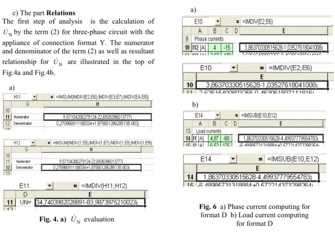
c) The part Relations
The first step of analysis is the calculation of
N
U by the term (2) for three-phase circuit with the appliance of connection format Y. The numerator and denominator of the term (2) as well as resultant relationship for UN are illustrated in the top of Fig.4a and Fig.4b.
The next step of analysis is determination of the voltages on the all appliance phases as subtractions
1 N
U −U , U2 −UN, U3−UN
in the term (1) and it is shown in the Fig.5.
The basic step of analysis is determination of phase and load current phasors for three-phase circuit with the appliance of connection format D. This step is illustrated in the Fig. 6a and 6b.
Fig.3 Conversion of input parameters to CN b)
Fig. 2. b) Defined parameters and their conversion on the CN
for format D.
a)
Fig. 4. a) UN evaluation
Fig. 5 Voltages of appliance phases computing
Fig. 6 a) Phase current computing for format D b) Load current computing
for format D a)
b)
Fig. 4. b) UN evaluation b)
The power calculations are made according to terms (6) - (8). Complex power on the appliance of format D calculation is illustrated in the Fig. 7, corresponding real and reactive power calculation is illustrated in the Fig. 8a and 8b. The functions on the top of Fig. 7 and 8 are used for calculating complex, real and reactive power on the appliance of format Y such as for format D.
d) The part Results:
The complete analysis results for the appliance of format D is in the Fig. 9a and for the appliance of format Y is in the Fig. 9b.
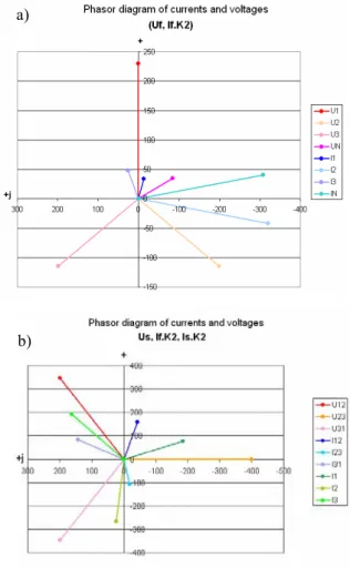
e) The part Phasor diagram
The phasor diagram of voltage and current phasors is in the Fig.10a) for the appliance of format Y and
in the Fig.10b) for the appliance of format D. Because of very different voltage and current amplitudes was the current amplitude proportional adapted (Fig.11).
CONCLUSION
Presented programs grant to do the full analysis of three-phase circuits with appliance connected in the form Y and in the form D. The failure states (short connection or disconnection of some phase) analysis is also possible, but impedance of short connection phase is suggested to be simulated by number 10−20 (not by 0) and impedance of
disconnection phase is suggested to be simulated with number 1020.
Fig. 11 The exampple proportional adapted currents for phasor diagram
a) b)
Fig.9 Analysis results for appliance format a) Y b) D
Fig. 10 The phasor diagram of voltage and current phasors
a) for the appliance of format Y b) for the appliance of format D a)
b)
Fig. 8 Calculation of the a) real power b) reactive power for appliance of format D.
These programs can be found on the http://www.tuke.sk/fei-kteem/aei06/y.xls and http://www.tuke.sk/fei-kteem/aei06/d.xls.
They can be used in Open Office, which is unlike Excel free.
Our goal is to prepare studying materials for the course Theory of electrical engineering with included programs in Excel for
graphical illustration of analysis results for the circuits with anharmonic sources,
full computer processing three-phase circuits analysis with graphic illustration of results in the form of phasor diagrams,
graphic illustration of analysis results for the simple circuits with pulse on the input,
full computer processing of long distance line analysis including graphics illustration of results.
REFERENCES
[1] Brož, M.: Mistrovství v Microsoft Excel 2000 a 2002, Computer Press, Praha, 2002.
(in Czech)
[2] Mayer,D.: Úvod do teorie elektrických obvodů, SNTL/ALFA, Praha, 1981
BIOGRAPHIES
Darina Špaldonová (doc, RNDr, CSc) was born in Košice in 1954. In 1976 she graduated at P. J. Šarárik University in Košice, in 1983 received the RNDr (MSc) degree at this university and in 1994 CSc (PhD) degree in theory of electrical engineering at Slovak University of Technology, Bratislava. In 1998 she was appointed Associate Professor of theory of electrical engineering at the Department of Electrical engineering and Electrical Measurement of the Technical university of Košice. Her current interests include circuit theory and theory of electromagnetic field.
Milan Guzan (Ing, PhD) was born in 1969 in Snina, Slovak Republic. He received the Ing. (M.Sc.) degree in electrical engineering from the Faculty of Electrical Engineering and Informatics at Technical University of Košice in 1992. In 2002 he defended his PhD in the field Elektronika. At present he is an assistant professor at the Department of Electrical engineering and Electrical Measurement of the Technical university of Košice. His research interests are: multiple–valued logic, state space, Chua`s circuit and chaos.