PERFORMANCE
by Xiaohu Fan
A dissertation submitted in partial fulfillment of the requirements for the degree of
Doctor of Philosophy (Civil Engineering) in the University of Michigan
2014
Doctoral Committee:
Assistant Professor Jason P. McCormick, Chair Professor Carlos Cesnik
Professor Sherif El-Tawil
iii of this dissertation.
Throughout my career in graduate school, I have been fortunate to glean mentorship, friendship, and love in addition to a doctoral degree. There have been many people who have had an influence in my five years of living in Ann Arbor, Michigan. Good times of being together always come to an end, but those dear memories will never fade and only grow stronger.
I am grateful that I get to become friends with a great advisor and person, Dr. Jason McCormick, who has offered me continuous mentorship, guidance, and friendship. His encouragement and support helped me fight through the many times when I doubted myself and even the career choice in this profession. His technical competency and scope of knowledge, exceptional work ethics, and high moral standards have all had a deep imprint in shaping the scholar that I am today. I would also like to acknowledge Dr. Cesnik, Dr. El-Tawil, and Dr. Parra-Montesinos for their commitment to my academic success. Their advice and inspiration have contributed greatly to making my doctoral dissertation stronger. I look up to them and view them as my role models based on their success in both life and career.
Without the help and expertise of the structural engineering laboratory technicians, Bob Spence, Bob Fisher, and Jan Pantolin, the experimental work in this dissertation would never be finished so smoothly and on time. I sincerely appreciate their assistance and all the interesting conversations that made the experimental work less strenuous and more fun.
I have been looked after by many great friends every time I needed help or support. Because of them, life in a different country far from home becomes lively and promising,
iv
support, and sacrifices are the reason that I can come this far and the motivation that I want to accomplish more.
I will always have a special sentiment for Ann Arbor because this is where I found my beloved fiancée, Qianru Guo. She has made my life so much more promising and colorful. I feel fortunate and grateful that I get to hold her hands to enjoy the beauty of life and love.
v
LIST OF TABLES ... xi
LIST OF FIGURES ... xiii
ABSTRACT ... xxv
CHAPTER 1 INTRODUCTION ... 1
1.1 Motivation ... 1
1.2 Research Objectives ... 3
1.3 Dissertation Outline ... 5
CHAPTER 2 LITERATURE REVIEW ... 9
2.1 Hazards Affecting Highway Infrastructure in the CEUS ... 9
2.1.1 Seismicity in the CEUS ... 9
2.1.2 Age-related corrosion of highway infrastructure ... 10
2.2 Steel Bridge Bearings ... 14
2.2.1 Overview of steel bearings ... 14
2.2.2 Definition and AASHTO Specifications ... 14
2.2.3 Behavior of steel bearings ... 16
2.3 Seismic Performance of Highway Infrastructure ... 21
CHAPTER 3 THEORETICAL ANALYSIS OF STEEL BRIDGE BEARINGS... 31
3.1 Introduction ... 31
3.2 Rigid Body Kinematics of Steel Rocker Bearings ... 31
vi
3.5 Summary ... 40
CHAPTER 4 FINITE ELEMENT MODELING OF STEEL BRIDGE BEARINGS .. 44
4.1 Introduction ... 44
4.2 Modeling Procedure ... 46
4.2.1 Material model ... 46
4.2.2 Model description ... 46
4.2.3 Loading and boundary conditions ... 48
4.2.4 Other modeling details ... 48
4.3 Steel Rocker Bearing Behavior ... 49
4.3.1 Longitudinal response of the rocker bearing ... 49
4.3.2 Transverse response of the rocker bearing ... 51
4.4 Steel Bolster Bearing Behavior ... 54
4.4.1 Longitudinal response of the bolster bearing ... 54
4.4.2 Transverse response of the bolster bearing ... 56
4.5 Bearing Capacity ... 58
4.6 Summary ... 60
CHAPTER 5 CORROSION CHARACTERIZATION OF SALVAGED STEEL BEARINGS 72 5.1 Introduction ... 72
vii
6.2 Experimental Program Overview ... 82
6.2.1 Test setup ... 82
6.2.2 Instrumentation ... 83
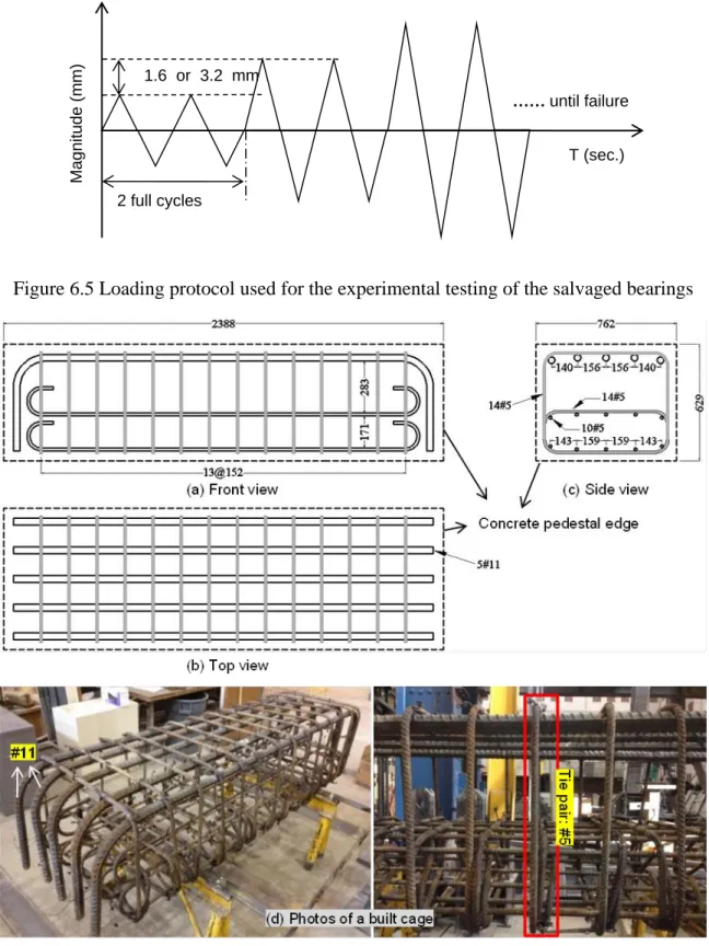
6.2.3 Loading protocol ... 83
6.2.4 Concrete pedestal ... 84
6.2.5 Steel bearing specimens and test matrix ... 86
6.2.6 Steel anchor bolts ... 87
6.3 Monotonic Behavior of Steel Bearings ... 96
6.3.1 Longitudinal response of abutment rocker bearings ... 97
6.3.2 Transverse response of abutment rocker bearings ... 105
6.3.3 Longitudinal response of pier rocker bearings... 111
6.3.4 Transverse response of pier rocker bearings ... 112
6.3.5 Corrosion effect on steel rocker bearing monotonic behavior ... 112
6.3.6 Longitudinal response of steel bolster bearings ... 121
6.3.7 Transverse response of steel bolster bearings ... 122
6.3.8 Summary of steel bolster bearing monotonic tests ... 122
6.4 Cyclic Behavior of Steel Bearings on a Steel Pedestal ... 129
6.4.1 Longitudinal cyclic response of abutment rocker bearings ... 129
6.4.2 Transverse cyclic response of abutment rocker bearings ... 137
viii
6.5 Cyclic Behavior of Steel Bearings on a Concrete Pedestal ... 162
6.5.1 Longitudinal cyclic response of steel bolster bearings using 25.4 mm anchor bolts ... 162
6.5.2 Transverse cyclic response of steel bolster bearings using 25.4 mm anchor bolts 164 6.5.3 Longitudinal cyclic response of steel bolster bearings using 34.9 mm anchor bolts ... 173
6.5.4 Transverse cyclic response of steel bolster bearings using 34.9 mm anchor bolts 174 6.5.5 Summary of steel bearing-concrete pedestal assembly tests ... 175
6.6 Summary ... 176
CHAPTER 7 EFFECT OF STEEL BEARING BEHAVIOR ON BRIDGE PERFORMANCE ... 182
7.1 Introduction ... 182
7.2 Overview of the Prototype Bridge ... 182
7.3 Analytical Models of Steel Bearings ... 186
7.3.1 Steel rocker bearing models with minor corrosion ... 187
7.3.2 Steel rocker bearing models with severe corrosion ... 191
7.3.3 Steel rocker bearing model with corrosion cleaned ... 195
7.3.4 Steel bolster bearing model without corrosion ... 205
ix
7.5 Other Simulation Details ... 229
7.5.1 Characteristics of the Selected Ground Motions ... 229
7.5.2 Failure criteria of steel bridge bearings ... 234
7.5.3 Scope of the simulation parameters ... 234
7.6 Seismic Bridge Performance Subjected to 10in50 Ground Motions ... 236
7.6.1 Superstructure displacement time histories ... 236
7.6.2 Substructure displacement time histories... 238
7.6.3 Abutment-soil interaction ... 243
7.6.4 Pounding response at the abutment ... 243
7.6.5 Steel rocker bearing response at the abutment ... 247
7.6.6 Steel rocker bearing response at the pier ... 248
7.6.7 Steel bolster bearing response at the pier ... 252
7.6.8 Wall pier base moment-curvature response ... 253
7.7 Seismic Bridge Performance Subjected to 2in50 Ground Motions ... 257
7.7.1 Superstructure displacement time histories ... 257
7.7.2 Substructure displacement time histories... 259
7.7.3 Abutment-soil interaction ... 264
7.7.4 Impact response due to pounding ... 265
7.7.5 Steel rocker bearing response at the abutment ... 268
x
7.8.3 Abutment rocker bearing response distributions ... 283
7.8.4 Pier rocker bearing response distributions ... 286
7.8.5 Pier bolster bearing response distributions ... 289
7.8.6 Wall pier moment distributions ... 290
7.9 Summary ... 294
CHAPTER 8 SUMMARY AND CONCLUSIONS... 296
8.1 Summary and Conclusions ... 296
8.1.1 Analytical and FE modeling of steel bearings ... 297
8.1.2 Experimental characterization and testing of salvaged steel bearings ... 298
8.1.3 Performance evaluation of highway bridges using time-history analyses 305 8.2 Impact ... 307
8.3 Limitations and Future Recommendations ... 308
xi
Table 3.3 Strength and failure mode of the bolster bearing ... 39
Table 4.1 Dead loads acting on the Meridian bridge bearings based on location ... 48
Table 4.2 Comparison of the maximum resistance obtained from the finite element pushover analysis and theoretical prediction for the steel bearing under monotonic loading (kN) ... 59
Table 5.1 Coefficient values for Equation 5-1 (Albrecht and Naeemi 1994) ... 73
Table 5.2 Qualitative account of corrosion location, observations, and effect on the behavior of steel rocker and bolster bearings ... 75
Table 5.3 Mass and section loss statistics for eight abutment steel rocker bearings ... 78
Table 6.1 Past loading patterns for tests of steel bearings and pedestals ... 84
Table 6.2 Inventory of the salvaged steel bearings ... 95
Table 6.3 Experimental test matrix of the steel bearings ... 96
Table 6.4 Summary of the monotonic test results for the steel rocker bearings under longitudinal displacements... 120
Table 6.5 Summary of the monotonic test results for the steel rocker bearings under transverse displacements ... 120
Table 6.6 Summary of the longitudinal cyclic test results for steel rocker bearings with varying corrosion levels ... 152
Table 6.7 Summary of the transverse cyclic test results for steel rocker bearings with varying corrosion levels ... 152
Table 6.8 Summary of the cyclic behavior of the steel bolster bearings with minor corrosion ... 161
Table 6.9 Summary of the cyclic test results of the steel bolster bearing-concrete pedestal assemblies ... 175
xii
Table 7.4 OpenSees models and parameters used in the rocker bearing longitudinal model
with severe corrosion ... 194
Table 7.5 OpenSees models and parameters used in the rocker bearing transverse model with severe corrosion ... 194
Table 7.6 OpenSees models and parameters used in the rocker bearing longitudinal model with corrosion cleaned ... 198
Table 7.7 OpenSees models and parameters used in the rocker bearing transverse model with corrosion cleaned ... 198
Table 7.8 OpenSees models and parameters used in the bolster bearing longitudinal model... 208
Table 7.9 OpenSees models and parameters used in the bolster bearing transverse model ... 208
Table 7.10 Details of the 10% exceedence in 50 years Boston ground motions ... 231
Table 7.11 Details of the 2% exceedence in 50 years Boston ground motions ... 232
xiii
Figure 1.2 Plan drawing of the highway bridge from which the steel bearings were salvaged with all dimensions given in mm ... 7 Figure 1.3 Toppled rocker bearing failures: (a) Birmingham Bridge (Splitstone et al. 2010)
and (b) Dunn Memorial Bridge (NYSDOT 2005) ... 8 Figure 2.1 The New Madrid seismic zone with its seismicity denoted by red dots (NMSZ Expert Panel 2011) ... 23 Figure 2.2 Seismic activities within the NMSZ between 1974 and 2011 (CERI 2011) ... 24 Figure 2.3 U.S. Geological Survey hazard map of the United States for a probability of exceedance of 2% in 50 years (USGS 2008) ... 24 Figure 2.4 Uniform corrosion at the bottom contact surface of a rocker bearing (modified from Balassone (2010))... 25 Figure 2.5 Side view of a bolster and rocker bearings found in the Central and Eastern U.S. ... 25 Figure 2.6 Configuration of the steel bearings studied by Mander et al. (1996) ... 25 Figure 2.7 Longitudinal test results for the high type rocker bearings (Mander et al. 1996)
... 26 Figure 2.8 Transverse test results for the high type rocker bearings (Mander et al. 1996)
... 26 Figure 2.9 Longitudinal test results for the high type fixed bearings (Mander et al. 1996)
... 27 Figure 2.10 Transverse test results for the high type fixed bearings (Mander et al. 1996)
... 27 Figure 2.11 Longitudinal test results for the high type fixed bearings on a concrete pedestal (Mander et al. 1996)... 28
xiv
Figure 2.15 Steel bearing failures observed during the: (a) 1995 Kobe earthquake and (b) 2011 Tohoku earthquake ... 30 Figure 3.1 Free body diagram of a longitudinally displaced rocker bearing ... 41 Figure 3.2 Free body diagram for determining the critical applied load for a rocker bearing displaced in the transverse direction ... 41 Figure 3.3 Free body diagram of a bolster bearing at its ultimate state under longitudinal loading... 42 Figure 3.4 Free body diagram of a bolster bearing at its ultimate state under transverse loading... 42 Figure 3.5 Dimensions of the studied rocker bearing and its components ... 43 Figure 3.6 Dimensions of the studied bolster bearing and its components ... 43 Figure 4.1 Illustrations and mesh of the 3-D finite element models of the (a) bolster and (b) rocker bearing ... 62 Figure 4.2 Steel material model used for all steel components of the bearings ... 62 Figure 4.3 Illustration of the contact interface between the rocker body and masonry plate in the finite element model ... 63 Figure 4.4 Interaction definition for the anchor bolt and its contact interfaces ... 63 Figure 4.5 Longitudinal response of the steel rocker bearing under (a) reversed loading cycles with equal displacement magnitude and (b) increasing displacement magnitudes ... 64 Figure 4.6 Longitudinal response of the steel rocker bearing under a single loading cycle considering the effect of the (a) friction coefficient and (b) gravity load ... 65 Figure 4.7 Transverse response of the steel rocker bearing under (a) reversed loading cycles with equal displacement magnitude and (b) increasing displacement magnitudes ... 66
xv
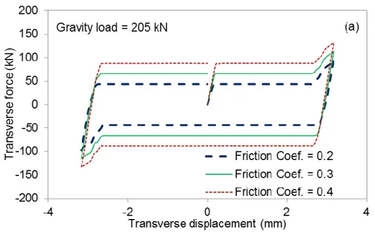
cycle considering the effect of the (a) friction coefficient and (b) gravity load ... 69
Figure 4.11 Transverse response of the steel bolster bearing under (a) reversed loading cycles with equal displacement magnitude and (b) increasing displacement magnitudes ... 70
Figure 4.12 Transverse response of the steel bolster bearing under a single loading cycle considering the effect of the (a) friction coefficient and (b) gravity load ... 71
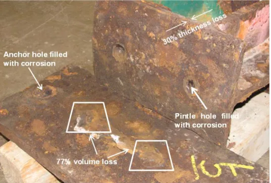
Figure 5.1 Illustration of various corrosion locations and effects on a steel rocker bearing salvaged from an abutment ... 80
Figure 5.2 Box plots of mass and section loss distributions for eight abutment steel rocker bearings ... 80
Figure 6.1 Experimental test setup with (a) a steel pedestal and (b) a concrete pedestal . 88 Figure 6.2 Photograph of the bearing test setup ... 89
Figure 6.3 Load cell fixture illustrations: (a) 3-D diagram and (b) photograph ... 90
Figure 6.4 Optotrak marker layout on a steel bearing specimen: (a) diagram and (b) photograph ... 91
Figure 6.5 Loading protocol used for the experimental testing of the salvaged bearings 92 Figure 6.6 Design of the reinforcement cage of the concrete pedestals (unit of dimensions: mm) ... 92
Figure 6.7 Photographs of one reinforced concrete pedestal: (a) reinforcement cage inside the form work and (b) poured concrete pedestal ... 93
Figure 6.8 Layout of anchor bolts in the concrete pedestal (units are in mm) ... 94
Figure 6.9 Tensile test results of the anchor bolts ... 94
Figure 6.10 Abutment rocker bearing #5 (AR5) in its as-received condition ... 101
Figure 6.11 Top cylindrical rolling surface of AR5 before rust removal ... 101
xvi
received condition under positive and negative monotonic loading ... 104
Figure 6.17 Full longitudinal response of the abutment rocker bearing (AR5) in the cleaned condition under positive and negative monotonic loading ... 104
Figure 6.18 Abutment rocker bearing #25 (AR25) in its as-received condition ... 107
Figure 6.19 Top cylindrical contact surface of AR25 before rust removal ... 107
Figure 6.20 Bottom contact interface of the AR25 bearing in the as-received condition ... 108
Figure 6.21 Bearing AR25 with rust removed after the initial monotonic tests ... 108
Figure 6.22 Cleaned bottom contact interface of bearing AR25 ... 109
Figure 6.23 Test photographs of the as-received AR25 bearing under negative monotonic loading... 109
Figure 6.24 Transverse response of the AR25 bearing in the as-received condition under negative monotonic loading ... 110
Figure 6.25 Transverse response of the AR25 bearing in the cleaned condition under negative monotonic loading ... 110
Figure 6.26 Pier rocker bearing #18 (PR18) in the as-received condition ... 115
Figure 6.27 Top cylindrical contact surface of Bearing PR18 ... 115
Figure 6.28 Bottom contact interface of Bearing PR18 in the as-received condition .... 116
Figure 6.29 Test photographs for Bearing PR18 under (a) positive monotonic loading and (b) negative monotonic loading ... 116
Figure 6.30 The full longitudinal response of Bearing PR18 in the as-received condition under positive and negative monotonic loading ... 117
Figure 6.31 Pier rocker bearing #19 (PR19) in the as-received condition ... 117
Figure 6.32 Top cylindrical contact surface of Bearing PR19 ... 118
xvii
Figure 6.38 Photographs of Bearing PB12 under longitudinal monotonic loading ... 125 Figure 6.39 Longitudinal response of Bearing PB12 in the as-received condition under negative monotonic loading ... 126 Figure 6.40 Pier bolster bearing #14 (PB14) in the as-received condition ... 126 Figure 6.41 Photographs of Bearing PB14 under transverse monotonic loading ... 127 Figure 6.42 Transverse response of Bearing PB14 in the as-received condition under negative monotonic loading ... 128 Figure 6.43 Abutment rocker bearing #21 (AR21) in the as-received condition ... 132 Figure 6.44 Top cylindrical contact surface of Bearing AR21 in the as-received condition
... 132 Figure 6.45 Bottom contact interface of Bearing AR21 in the as-received condition .... 133 Figure 6.46 Bearing AR21 with surface rust removed ... 133 Figure 6.47 Cleaned bottom contact surfaces of Bearing AR21 ... 134 Figure 6.48 Photograph of the instrumentation used for testing Bearing AR21 ... 134 Figure 6.49 Actual loading protocol for the test of Bearing AR21 in the as-received condition ... 135 Figure 6.50 Longitudinal cyclic response of Bearing AR21 in the as-received condition
... 135 Figure 6.51 Actual loading protocol for the test of Bearing AR21 in the cleaned condition
... 136 Figure 6.52 Longitudinal cyclic response of Bearing AR21 in the cleaned condition ... 136 Figure 6.53 Abutment rocker bearing #23 (AR23) in the as-received condition ... 139 Figure 6.54 Top cylindrical surface of Bearing AR23 in the as-received condition ... 139 Figure 6.55 Bottom contact interface of Bearing AR23 in the as-received condition .... 140 Figure 6.56 Bearing AR23 in its cleaned condition with rust removed ... 140
xviii
Figure 6.62 Transverse cyclic response of Bearing AR23 in the cleaned condition ... 143
Figure 6.63 Pier rocker bearing #8 (PR8) in the as-received condition ... 145
Figure 6.64 Top cylindrical surface of Bearing PR8 in the as-received condition ... 145
Figure 6.65 Bottom contact interface of Bearing PR8 in the as-received condition ... 146
Figure 6.66 Photographs of Bearing PR8 under longitudinal loading ... 146
Figure 6.67 Actual loading history recorded during testing of Bearing PR8 ... 147
Figure 6.68 Longitudinal cyclic response of Bearing PR8 in the as-received condition 147 Figure 6.69 Actual loading protocol recorded during testing of Bearing PR19 ... 151
Figure 6.70 Transverse response of Bearing PR19 under cyclic loading in the as-received condition ... 151
Figure 6.71 Photographs during testing of Bearing PB14 and after completion of loading ... 156
Figure 6.72 Actual loading protocol recorded during testing of Bearing PB14 ... 157
Figure 6.73 Longitudinal cyclic response of Bearing PB14 in the as-received condition ... 157
Figure 6.74 Pier bolster bearing #13 (PB13) in the as-received condition ... 158
Figure 6.75 Top contact surface with pintles of Bearing PB13 in the as-received condition ... 158
Figure 6.76 Photographs of Bearing PB13 taken during and after cyclic loading ... 159
Figure 6.77 Actual loading protocol recorded during test of Bearing PB13 ... 160
Figure 6.78 Transverse cyclic response of Bearing PB13 in the as-received condition . 160 Figure 6.79 Pier bolster bearing #15 (PB15) in the as-received condition ... 166
Figure 6.80 Actual loading protocol recorded during cyclic testing of Bearing PB15 ... 167
Figure 6.81 Longitudinal cyclic response of Bearing PB15 on a concrete pedestal and using anchor bolts with a 25.4 mm diameter ... 167
xix
Figure 6.85 Pier bolster bearing #11 (PB11) in the as-received condition ... 169 Figure 6.86 Actual loading history recorded during cyclic testing of Bearing PB11 ... 170 Figure 6.87 Transverse cyclic response of Bearing PB11 on a concrete pedestal and using anchor bolts with a 25.4 mm diameter ... 170 Figure 6.88 Photograph showing the rocking deformation mode of the bolster bearing 171 Figure 6.89 Photograph showing the severely deformed and fractured anchor bolt ... 171 Figure 6.90 Photograph showing concrete pedestal surface damage due to digging of the shim plate ... 172 Figure 6.91 Photographs of the damaged concrete pedestal and anchor bolts due to bolt pullout and fracture ... 172 Figure 6.92 Actual loading protocol used in the test of Bearing PB11 on a concrete pedestal with 34.9 mm diameter anchor bolts ... 178 Figure 6.93 Longitudinal cyclic response of Bearing PB11 on a concrete pedestal with 34.9 mm diameter bolts ... 178 Figure 6.94 Photographs showing bolt pullout and bearing rocking behavior ... 179 Figure 6.95 Photograph taken post-test showing the extent of bolt pullout accumulated during cyclic testing ... 179 Figure 6.96 Photographs of the reinforced concrete pedestal taken after the cyclic test showing concrete cracking and bolt damage ... 180 Figure 6.97 Photograph of the pintles taken after the cyclic test ... 180 Figure 6.98 Actual loading history recorded during testing of Bearing PB15 on a concrete pedestal with 34.9 mm diameter anchor bolts ... 181 Figure 6.99 Transverse cyclic response of bearing PB15 on a concrete pedestal with 34.9 mm diameter anchor bolts ... 181 Figure 7.1 Plan and configuration of the Meridian bridge ... 185
xx
capture rocking behavior, (d) Hysteretic model used to capture softening, and (e) comparison between the simulated and experimental responses ... 200 Figure 7.4 Steel rocker bearing with severe corrosion longitudinal behavior model: (a) backbone curve, (b) Steel01 model used to model rolling, (c) ElasticMultiLinear model used to capture rocking, (d) ElasticPPGap model used to capture crushing of rust, and (e) comparison between the simulated and experimental responses 201 Figure 7.5 Steel rocker bearing with severe corrosion transverse behavior model: (a) backbone curve, (b) Steel01 model used to model friction, (c) ElasticPPGap model used to capture positive rocking and yielding, (d) ElasticPPGap model for negative rocking and yielding, and (e) comparison between the simulated and experimental responses ... 202 Figure 7.6 Steel rocker bearing with corrosion cleaned longitudinal behavior model: (a) backbone curve, (b) Steel01 model used to model rolling, (c) ElasticMultiLinear model used to capture rocking, and (d) comparison between the simulated and experimental responses ... 203 Figure 7.7 Steel rocker bearing with corrosion cleaned transverse behavior model: (a) backbone curve, (b) Steel01 model used to model friction, (c) ElasticPPGap model used to capture positive rocking and yielding, (d) ElasticPPGap model for negative rocking and yielding, and (e) comparison between the simulated and experimental responses ... 204 Figure 7.8 Steel bolster bearing longitudinal behavior model: (a) backbone curve, (b) Steel01 model used to model friction, (c) Hysteretic model used to capture yielding and fracture, (d) ElasticMultiLinear model used to capture rocking behavior, and (e) comparison between the simulated and experimental responses ... 209
xxi
the cap beam and wall pier ... 215 Figure 7.12 Comparison between OpenSees and experimental results of the cyclic behavior of wall piers (Filipov (2012)) ... 216 Figure 7.13 Concrete and steel material models used to model the behavior of the wall pier ... 217 Figure 7.14 Passive and active abutment models ... 223 Figure 7.15 Abutment element and its longitudinal and transverse cyclic behavior ... 224 Figure 7.16 Schematic of pounding between the superstructure and abutment under ground motions ... 225 Figure 7.17 Pounding model between the superstructure and abutment (Muthukumar and DesRoches 2006) ... 225 Figure 7.18 Simulated cyclic pounding response using the bilinear pounding model ... 226 Figure 7.19 Stiffness calculation procedure for modeling the pile group foundation .... 228 Figure 7.20 Response spectra for the normal (longitudinal) components of the 10 in 50 Boston ground motions ... 231 Figure 7.21 Response spectra for the parallel (transverse) components of the 10 in 50 Boston ground motions ... 232 Figure 7.22 Response spectra for the normal (longitudinal) components of the 2 in 50 Boston ground motions ... 233 Figure 7.23 Response spectra for the parallel (transverse) components of the 2 in 50 Boston ground motions ... 233 Figure 7.24 Schematic of the bridge model used in the numerical simulations ... 236 Figure 7.25 Superstructure and abutments displacement time histories of Bridge C under bidirectional 10in50 Boston motion pair, bo05 and bo06... 240
xxii
Figure 7.29 Wall pier relative displacement time histories of Bridge P under bidirectional 10in50 Boston motion pair, bo05 and bo06 ... 242 Figure 7.30 Comparison of middle wall pier relative displacement time histories under
bidirectional 10in50 Boston motion pair of bo05 and bo06 between Bridge C and Bridge P ... 242 Figure 7.31 Abutment soil interaction response of Bridge C under the bidirectional ground motion pair of bo05 and bo06... 245 Figure 7.32 Abutment soil interaction response of Bridge P under the bidirectional ground motion pair of bo05 and bo06... 245 Figure 7.33 Impact responses due to pounding between the deck and abutments for both Bridge C and Bridge P under bidirectional ground motion pair bo05 and bo06 246 Figure 7.34 Steel rocker bearing response at the abutment of Bridge C under the bidirectional ground motion pair of bo05 and bo06 ... 250 Figure 7.35 Steel rocker bearing response at the abutment of Bridge P under the bidirectional ground motion pair of bo05 and bo06 ... 250 Figure 7.36 Steel rocker bearing response at the pier of Bridge C under the bidirectional ground motion pair of bo05 and bo06... 251 Figure 7.37 Steel rocker bearing response at the pier of Bridge P under the bidirectional ground motion pair of bo05 and bo06... 251 Figure 7.38 Steel bolster bearing response at the pier of Bridge C under the bidirectional ground motion pair of bo05 and bo06... 255 Figure 7.39 Steel bolster bearing response at the pier of Bridge P under the bidirectional ground motion pair of bo05 and bo06... 255 Figure 7.40 The moment-curvature response at the base of the middle wall pier of Bridge C under the 10in50 bidirectional ground motion pair of bo05 and bo06... 256
xxiii
Figure 7.44 Comparison of superstructure displacement time histories under bidirectional 2in50 motion pair of bo35 and bo36 between Bridge C and Bridge P ... 262 Figure 7.45 Wall pier displacement time histories of Bridge C under the bidirectional 2in50 motion pair of bo35 and bo36 ... 262 Figure 7.46 Wall pier displacement time histories of Bridge P under the bidirectional 2in50 motion pair of bo35 and bo36 ... 263 Figure 7.47 Comparison of middle wall pier displacement time histories under the bidirectional 2in50 motion pair of bo35 and bo36 between Bridge C and Bridge P ... 263 Figure 7.48 Abutment soil interaction response of Bridge C under the bidirectional 2in50 ground motion pair of bo05 and bo06... 266 Figure 7.49 Abutment soil interaction response of Bridge P under the bidirectional 2in50 ground motion pair of bo05 and bo06... 266 Figure 7.50 Impact responses due to pounding between the deck and abutments for both Bridge C and Bridge P under the bidirectional 2in50 ground motion pair of bo35 and bo36 ... 267 Figure 7.51 Steel rocker bearing response at the abutment of Bridge C under the bidirectional 2in50 ground motion pair of bo35 and bo36 ... 273 Figure 7.52 Steel rocker bearing response at the abutment of Bridge P under the bidirectional 2in50 ground motion pair of bo35 and bo36 ... 273 Figure 7.53 Steel rocker bearing response at the pier of Bridge C under the bidirectional 2in50 ground motion pair of bo35 and bo36 ... 274 Figure 7.54 Steel rocker bearing response at the pier of Bridge P under the bidirectional 2in50 ground motion pair of bo35 and bo36 ... 274
xxiv
Figure 7.58 The moment-curvature response at the base of the middle wall pier of Bridge P under the 2in50 bidirectional ground motion pair of bo35 and bo36 ... 276 Figure 7.59 Longitudinal abutment-soil force response distributions for Bridge C and Bridge P under both the 10in50 and 2in50 ground motions ... 281 Figure 7.60 Transverse abutment-soil force response distributions for Bridge C and Bridge P under both the 10in50 and 2in50 ground motions ... 281 Figure 7.61 Longitudinal impact force response distributions for Bridge C and Bridge P under both the 10in50 and 2in50 ground motions ... 282 Figure 7.62 Longitudinal abutment rocker bearing deformation response distributions for Bridge C and Bridge P under both the 10in50 and 2in50 ground motions ... 285 Figure 7.63 Transverse abutment rocker bearing deformation response distributions for Bridge C and Bridge P under both the 10in50 and 2in50 ground motions ... 285 Figure 7.64 Longitudinal pier rocker bearing deformation response distributions for Bridge C and Bridge P under both the 10in50 and 2in50 ground motions ... 288 Figure 7.65 Transverse pier rocker bearing deformation response distributions for Bridge C and Bridge P under both the 10in50 and 2in50 ground motions ... 288 Figure 7.66 Longitudinal pier bolster bearing deformation response distributions for Bridge C and Bridge P under both the 10in50 and 2in50 ground motions ... 292 Figure 7.67 Transverse pier bolster bearing deformation response distributions for Bridge C and Bridge P under both the 10in50 and 2in50 ground motions ... 292 Figure 7.68 Weak-axis bending moment distributions of the middle wall pier for Bridge C and Bridge P under both the 10in50 and 2in50 ground motions ... 293 Figure 7.69 Strong-axis bending moment distributions of the middle wall pier for Bridge C and Bridge P under both the 10in50 and 2in50 ground motions ... 293
xxv
provide a load transfer mechanism and accommodate movements between the superstructure and substructure. These bearings include steel rocker (expansion) bearings and steel bolster (fixed) bearings. Steel rocker bearings accommodate both translation and rotation of the superstructure, while steel bolster bearings only permit rotation of the superstructure under vehicle braking and thermal actions. Due to a lack of regular maintenance, the in-situ condition of these steel bearings, which have typically been in service for several decades, is often severely corroded. Moreover, these steel bearings are not designed for seismic loads due to a lack of understanding of the seismic hazard posed to bridges in the Central and Eastern United States (CEUS) at the time that many of these bridges were built. As awareness of their susceptibility to corrosion and vulnerability to seismic loads increases among bridge owners and engineers, the seismic performance of steel bridge bearings and their influence on the overall bridge system performance is of major concern, particularly given the importance the highway network plays in providing safe transportation and sustaining economic prosperity. For this reason, the goal of this study is to correlate corrosion level with the performance of steel bearings under seismic loads, thereby providing a means of more accurately assessing the vulnerability of in-situ bridges.
An analytical and finite element study is first undertaken to gain a preliminary understanding of the deformation modes, stiffness, and strength of the considered steel bearings. Corrosion loss quantification and large-scale experimental testing are then conducted on 25 salvaged steel bridge bearings aiming to provide an in-depth understanding of corrosion loss distribution and its influence on the cyclic behavior of steel bearings. Cyclic behavior of steel bearings is experimentally derived for two orthogonal (longitudinal and transverse) loading directions. Further, a portfolio of constitutive models that incorporate corrosion effects is created for the steel bridge
xxvi
Overall, the findings of this study show that significant corrosion can develop on steel bearings over their service life, which can result in major changes to the cyclic behavior of steel bearings with respect to deformation mode and failure pattern. The numerical simulations suggest that steel rocker bearings, when used in a continuous steel girder bridge, have the potential to topple in the longitudinal direction regardless of corrosion level. The bolster bearings also can lead to large forces transferred to the bridge wall piers.
1
Data from the United States National Bridge Inventory shows that there are over 600,000 bridges that make up the United States’ roadway network (FHWA 2010). Age-related deterioration of these bridges is becoming a significant concern as over half of the bridge inventory is approaching the end of its design life (AASHTO 2008). The recently released American Society of Civil Engineers (ASCE) report card gives the bridge inventory a Grade of C+ indicating a major area of need over the coming years as reflected by the fact that nearly a quarter of the bridge inventory is either structurally deficient or functionally obsolete (ASCE 2013). These findings clearly show the effect that deterioration has had on U.S. bridges, but a systematic means of addressing this problem is still lacking (AASHTO 2005, NSTPRSC 2008, and ASCE 2011). Among various phenomena associated with deterioration, corrosion of steel components of highway bridges is of particular concern due to the influence corrosion can have on component behavior and the potential large losses associated with bridge failures. For example, the 2007 collapse of the I35W bridge in Minnesota claimed 13 lives and injured 145 people (NTSB 2008). The accompanying economic and financial impact was in the millions of dollars (Xie and Levinson 2009).
Steel bearings, including rocker (expansion) and bolster (fixed) bearings (Figure 1.1), have been commonly used in highway bridges (Figure 1.2) throughout the Central and Eastern United States (Choi 2002). The main reason for their use is the relatively low cost of fabricating steel bearings and ease of installation. Deterioration in the form of corrosion of the bearing surfaces and debris buildup at the contact interfaces of steel bearings can have a significant influence on their mechanical behavior. Traffic disruption and financial losses due to past failures of ill conditioned steel bearings have emphasized
2
due to leaking expansion joints (Figure 1.3(a)). Another example of rocker bearing failure was the Dunn Memorial Bridge in Albany, New York. Two spans of the bridge dropped off the supporting rocker bearings (Figure 1.3(b)) partially due to excessive rotation caused by decades-long accumulation of debris and corrosion at the bottom contact interface of the rocker bearing, which restrained the mobility of the rocker and attracted undesired horizontal forces (NYSDOT 2005).
In addition to corrosion, the seismic hazard associated with the Central and Eastern United States (CEUS) creates another potential threat to the deteriorated bridge inventory in this region (Nielson and DesRoches 2006). The CEUS features a moderate seismicity with a long return period. Under a seismic event, the response of the older and deteriorated bridge inventory in the region is largely unknown. This lack of knowledge needs to be addressed to minimize potential loss of life and limit far reaching economic consequences of a seismic event on the transportation system. Many of these bridges depend on steel bearings to transfer loads between the superstructure and substructure and to contribute to the lateral force resistance under seismic loads. However, only a few studies in the past have considered the cyclic behavior of steel bridge bearings (Mander et al. 1996, Barker and Hartnagel 1998, and Steelman et al. 2013) as well as the seismic performance of highway bridges equipped with such bearings (DesRoches et al. 2004 and Bignell et al. 2005). The behavior of a number of steel bearing configurations still has yet to be considered under seismic loads. Moreover, among the limited literature available on steel bridge bearings, issues concerning corrosion and seismic performance are often addressed separately instead of considering the correlation between the two. As a result, there is a significant need for in-depth research on the performance of bearings and bridges under combined aging effects (i.e. corrosion) and seismic loads that quantitatively correlates corrosion level with behavior.
3
modeling, corrosion loss quantification, experimental testing of salvaged steel bridge bearings, and nonlinear time history analyses of a prototype deteriorated bridge under seismic excitations. The results from the bearing theoretical analyses, modeling, and testing provide previously non-existent information about the cyclic response of corroded steel rocker and bolster bearings. In addition to the distribution of corrosion on a bearing and among different bearing locations in a bridge system, the displacement capacity, lateral strength, and failure modes of corroded steel bearings under both monotonic and cyclic loads are obtained. The results from the nonlinear time history analyses of the bridge model are used to evaluate the effect of corrosion of the bearings on the overall bridge response leading to a better understanding of retrofit or replacement needs in areas of moderate to high seismicity.
The scope of this research focuses on evaluating the performance of steel bridge bearings typically found in the CEUS and identifying their vulnerability to the combined effects of corrosion and seismic loads allowing for the response of older in-situ steel bridges to be evaluated. Specifically, 25 steel bearings, salvaged from the Meridian Road bridge (Figure 1.2) in Rockford, IL, serve as the experimental specimens being studied. The Meridian Road bridge, chosen as the prototype bridge for this study, has four continuous spans symmetric about the middle pier wall with span lengths of 14 m and 17.8 m. The bridge superstructure consists of five parallel steel girders (W840×193 mm×kg/m) and a 178 mm thick reinforced concrete slab. More details in regard to the prototype bridge are provided in Chapter 3.
4 load from the superstructure.
Validate the finite element models through comparison with the theoretical analysis of steel rocker and bolster bearings.
Characterize the hysteretic behavior of rocker and bolster bearings in the longitudinal and transverse direction through a preliminary cyclic study to obtain relevant force data for the design of the experimental test setup to be used in Task 2.
Task 2 – Experimental Testing of Salvaged Steel Bearings:
Categorize the corrosion level of salvaged bearings that were previously installed in a bridge for over 50 years and quantify corrosion-induced weight loss and geometry changes.
Correlate corrosion levels with location where the bearing was installed in the bridge.
Characterize the cyclic behavior of steel rocker and bolster bearings for each corrosion category in the longitudinal and transverse directions under cyclic loading.
Investigate the effect of removing corrosion byproducts at the bearings’ surfaces on the bearing cyclic behavior.
Identify the failure modes of the bearing-pedestal assemblage. Correlate corrosion level with hysteretic behavior and failure modes.
5
Implement the analytical models of the steel bridge bearings into a full bridge model to consider the effect of corroded bridge bearings on the overall seismic response of a deteriorated continuous steel girder bridge.
Correlate the seismic performance of the bridge with the corrosion level of steel bearings to provide guidance for the seismic assessment of existing steel bridges.
1.3 Dissertation Outline
The organization of this dissertation consists of the following chapters:
Chapter 1 provides a brief introduction of the background and motivation for this research on corroded steel bridge bearings and the objectives of this project.
Chapter 2 offers a literature review of the major hazards (i.e. seismicity and corrosion) facing the highway infrastructure in the United States, steel bridge bearings and their vulnerability to corrosion, and lessons learned from the performance of bridges and their members, specifically steel bearings, during past seismic events.
Chapter 3 introduces an analytical study of the strength and stiffness of the steel bearings considered in this study. Rigid body kinematics is used to analyze the longitudinal rolling behavior and transverse instability of steel rocker bearings. Upper bounds for the steel bolster bearing strength in both longitudinal and transverse loading directions are estimated assuming a variety of failure modes including shear failure of the pintles and anchor bolts and combined tension and shear failure of the anchor bolts under rocking and prying.
6
Chapter 5 demonstrates the effect of corrosion on steel bearings with respect to their geometry and weight. The characteristics of atmospheric corrosion of steel bearings are discussed together with several existing corrosion loss prediction models.
Chapter 6 provides an extensive experimental program that was implemented to study the cyclic behavior of the steel bridge bearings in two orthogonal directions, longitudinal and transverse. The effect of corrosion on the bearings’ lateral cyclic response is investigated and discussed. Severely corroded bearings are also retested after removing the surface rust layers to investigate further the effect of corrosion.
Chapter 7 presents a numerical study of a full-scale computational model for a representative highway bridge typical of the CEUS. The experimental findings of the steel bearings regarding their lateral cyclic behavior are used to guide the development of a set of phenomenological bearing models that can accurately reproduce the bearing cyclic response in an efficient manner.
Chapter 8 summarizes the conclusions drawn from this study and outlines future research needs.
7
Figure 1.1 Schematic and picture showing corroded (a) bolster and (b) rocker bearings
Figure 1.2 Plan drawing of the highway bridge from which the steel bearings were salvaged with all dimensions given in mm
8
Figure 1.3 Toppled rocker bearing failures: (a) Birmingham Bridge (Splitstone et al. 2010) and (b) Dunn Memorial Bridge (NYSDOT 2005)
9 2.1.1 Seismicity in the CEUS
The New Madrid seismic zone (NMSZ) (Figure 2.1) and its extension, i.e. the Wabash Valley seismic zone (WVSZ), together with the Charleston seismic zone (CSZ) in South Carolina, are the major sources that pose a seismic threat to the CEUS (Merino et al. 2010). Seven states including Illinois, Indiana, Kentucky, Tennessee, Mississippi, Arkansas, and Missouri are located around the vicinity of the NMSZ. Between 1811 and 1812, three major earthquakes struck the area demonstrating the potential for significant seismic loads in the region. Although modern instrumentation was not available at that time, geologic evidence estimates the magnitudes of the aforementioned sequential events to be between 7.0 and 8.0, which are to date the largest known earthquakes for an intraplate seismic event (Johnston and Schweig 1996). Figure 2.2 illustrates locations and magnitudes of recorded seismic activities in the NMSZ since 1974 when modern seismological instrumentation was installed in the area. Recent studies of liquefaction features at over 250 sites across the NMSZ have suggested that the area has an average 500 year return period with an upper limit of 800 years and a lower limit of 200 years for sequential earthquake strikes resembling those events that occurred in 1811 and 1812 (Tuttle et al. 2002).
Figure 2.3 shows the current seismic hazard map of the United States. It is clear that the NMSZ and CSZ have a comparable hazard to that of the West Coast of the United States where more frequent inter-plate earthquakes occur. Moreover, a joint finding made by the Center of Earthquake Research and Information at the University of Memphis and the United States Geological Survey has estimated that the probability of an earthquake with
10
economic impact due to the density of the highway network and the number of larger urban areas.
The above discussion illustrates the seismic threat imposed on highway bridges in the Central and Eastern United States. In general, these bridges were not designed and constructed to resist seismic loads (Dicleli and Bruneau 1995) due to a lack of understanding of the region’s seismic hazard at the time. As a result, many existing highway bridges in this region are vulnerable to earthquakes because their structural members such as steel bearings are insufficient in withstanding the large lateral forces associated with earthquakes. Considering the importance of highway bridges to the economy and public safety in regards to freight transportation and commute, it is of particular concern to understand the behavior of older highway bridges under seismic loads so that feasible and sustainable retrofit schemes can be proposed to improve their survivability and serviceability during a moderate earthquake.
2.1.2 Age-related corrosion of highway infrastructure
Age-related deterioration of bridges manifests itself in a variety of forms including concrete cover spalling as a result of reinforcement corrosion, reduced capacity of steel girders due to corrosion-induced section loss, changes in the friction coefficient due to contact surface corrosion and debris buildup, and area loss of embedded anchor bolts over time. All of these forms of deterioration result from corrosion of steel components (reinforcement, connection elements, and members). Corrosion develops from the continued exposure of steel components or members to a chloride-rich environment within the presence of moisture and oxygen (Cramer et al. 2002). For highway bridges in the Central and Eastern U.S., the use of deicing solvents is a major source of chloride.
11
According to Fontana and Greene (1967), eight forms of corrosion are defined to categorize the corrosion phenomena with five of these specifically applying to bridge components (Kayser and Nowak 1989a).
Uniform Corrosion:
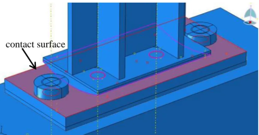
Also known as general corrosion, uniform corrosion is the most common form of corrosion and takes place over an entire exposed surface or a large area through an electrochemical reaction. Corrosion of the contact surfaces of steel bearings is an example of uniform corrosion (Figure 2.4). For a steel rocker bearing, uniform corrosion can cause buildup of debris and corrosion byproducts between the bottom contact surfaces along with a reduction of capacity and change in the behavior due to loss of surface area (Figure 1.3). As a result, corrosion can prevent movement of the rocker bearing leading to locking. Under cyclic loading, a locked rocker bearing at first performs like a fixed bearing attracting unexpected horizontal forces before the bond is broken and the ability to rotate is restored (Mander et al. 1996). The configuration of a bearing poses a challenge to continued routine maintenance of pre-painted surfaces at contact locations, which are where uniform corrosion can be most pervasive and has the largest effect on the behavior of a rocker bearing (Lindquist 2008).
Pitting:
Unlike uniform corrosion, pitting is more concentrated to a localized area. This localization of corrosion results in section loss that extends into the metal in the form of holes. Pitting is among the most destructive forms of corrosion and is difficult to detect as it is extremely localized and often concealed by corrosion byproducts. In addition, as a
12
Initiation of galvanic corrosion involves two dissimilar metals in contact with each other. The potential difference between the two metals produces an electron flow between the metals. The active metal among the two serves as the anode while the less active metal acts as the cathode. Usually the metal serving as the anode sustains severe corrosion while the other metal serving as the cathode corrodes very little or not at all. This form of corrosion can be found at bolted or welded connections where dissimilar metals may be in contact. For example, in a steel bearing assemblage, galvanic corrosion can be triggered between components made of stainless steel (i.e. anchor bolt) and carbon steel (i.e. masonry plate) (Lindquist-Hoeke et al. 2009). However, for the majority of older bridges, carbon steel typically was used throughout the entire bearing assemblage (Rashidi and Saadeghvaziri 1997).
Crevice Corrosion:
Crevice corrosion is found between surfaces in close contact or in shielded areas as a result of solutions rich in oxygen being trapped in these areas. This form of corrosion often occurs in holes, between faying surfaces, and at lap joints. Crevice corrosion often accompanies pitting as it can occur in the holes associated with pitting. For steel bearing assemblies, crevice corrosion can occur in the crevices between components of the anchor bolt (i.e. nut and washer) and between the masonry plate and the concrete pedestal (Lindquist 2008).
Stress Corrosion Cracking:
The simultaneous presence of tensile stress and a corrosive environment can induce stress corrosion cracking, which can lead to brittle failure of ductile materials (Lindquist-Hoeke et al. 2009). For mild carbon steel used in bridges, stress corrosion is usually not an issue
13
geometry changes, and buildup of debris and corrosion byproducts (Kayser and Nowak 1989a). Specifically for a steel bearing, section loss causes a reduction in the net area of the bearing available to withstand the dead load from the superstructure. Reduction of the section of a bolster bearing, particularly in the contact region, also can cause a decrease in stiffness and strength of the bearing under horizontal loads. These changes can lead to unexpected and nonuniform behavior under seismic loads. Buildup of debris and corrosion byproducts also can restrain free movement of a rocker bearing leading to adverse horizontal forces imparted to the superstructure and the substructure, unexpected behavior, and possible overturning of the rocker bearings (Figure 1.3).
Past studies have considered corroded steel girders (Kayser 1988) and corroded anchor bolts of steel bearings (Lindquist 2008). Kayser (1988) showed that corrosion can lead to a reduction in the bending, shear, and bearing resistance of steel girders as a result of thinned webs and flanges. Lindquist (2008), considering corrosion initiation mechanisms, systematically discussed the possibility of initiation of various corrosion forms for steel bearing anchor bolts. Findings of this study showed that galvanic corrosion and crevice corrosion are among the major forms of corrosion that prevail in the deterioration of anchor bolts. Neither of these studies looked at the effect of corrosion on the seismic performance of the bearings, which provide a load path for both vertical and lateral loads and accommodate relative movements between the superstructure and substructure in a bridge system. Thus, bearings deserve more research given the seismic hazard in the CEUS.
14
between the superstructure and substructure caused by thermal action and vehicular braking. Bearings also provide lateral resistance in both the longitudinal and the transverse direction under extreme loads such as collisions and earthquakes (Chen and Duan 2003). A variety of bearings have been used in practice where steel rocker bearings have been used for more than 100 years (Eggert and Kauschke 2002). In the CEUS, a large number of older bridges are equipped with steel bearings due to the number of bridges constructed in the mid 20th century when steel bearings were the most popular bearing type because of their cheap fabrication cost and ease for installation (Saadeghvaziri and Rashidi 1998; AASHTO 2008). For this reason, typical steel rocker and bolster bearings will be considered in this study since no studies have previously correlated their performance under seismic loads with corrosion level. The configuration of the studied bearings is illustrated in Figure 1.1 and various bearing components are labeled in Figure 2.5.
2.2.2 Definition and AASHTO Specifications
Bolster Bearing:
Also known as a fixed bearing, a bolster bearing (Figure 2.5(a)) has a single contact interface between the sole plate and the cylindrical surface at the top of the bearing. This configuration allows for rotation of the superstructure about the transverse axis. No translation is accommodated by the bolster bearing. According to Hertz theory, the theoretical contact zone for the bolster bearing at the contact interface is a line along the transverse direction that experiences infinite stress under dead loads and subsequently will yield to a rectangular plane reducing the infinite stress to a finite stress (Ramberger 2002). The considered bolster bearing assemblage, typical of that found in Illinois, is
15 Rocker Bearing:
A rocker bearing, as illustrated in Figure 2.5(b), has a pair of contact interfaces at the top and bottom of the rocker body, allowing the bearing to accommodate both translation and rotation of the superstructure. The rocker bearing has a rigid body with cylindrical top and bottom surfaces. Compared to the bolster bearing, the additional degree of freedom associated with the rocker bearing is attained through the extra contact interface at the bottom of the bearing body. To avoid transverse walking or sliding of a rocker bearing, pintles are located at both the top and bottom of the bearing at the point of contact.
AASHTO Specifications
The American Association of State Highway and Transportation Officials (AASHTO) modernized its specifications for seismic design of highway bridges in 2008 by incorporating a design earthquake with a 1,000 year return period that replaced the previous 500 year return period design earthquake. The 1st edition of the AASHTO Specifications for LRFD Seismic Bridge Design was published in 2009, which combined input and findings of several organizations in the bridge engineering community including ATC-32, Caltrans, the Multidisciplinary Center for Earthquake Engineering Research (MCEER), and the South Carolina Department of Transportation.
The current AASHTO LRFD Bridge Design Specifications (2010) offers seismic provisions for bridge bearings, including rocker and bolster bearings. The adoption of rocker bearings is not recommended for new bridge construction due to their limited displacement capacity as well as tendency toward tipping under seismic loads (AASHTO 2009). For this reason, it is important to understand their behavior in evaluating in-situ
16
address these concerns, the Illinois Department of Transportation initiated an earthquake resisting system (ERS) strategy in mid-2005 for the design and retrofit of highway bridges in Illinois to meet the new design earthquake requirements (Tobias et al. 2008). The main goal of this ERS strategy is to prevent span loss by allowing controlled damage at strategic locations in bridges such that seismic energy imparted to the bridge can be mitigated. This requires sacrificial connection elements (e.g. elastomeric bearings) between bridge superstructures and substructures that will under seismic loads act like fuses leading to prolonged periods and reduction of force demands on the substructure (Filipov et al. 2013).
2.2.3 Behavior of steel bearings
Although steel bearings have been used in bridge construction for over 100 years, research on the behavior of steel bearings is limited, particularly under large cyclic loads anticipated from an earthquake. The advent of modern aseismic bearing devices, such as base isolation systems, dampers, and active control devices, has exacerbated this situation since older steel bearings were replaced and abandoned in the traditional seismic zones along the West Coast (Mander et al. 1996). However, steel bearings are still regularly seen throughout the CEUS (Saadeghvaziri and Rashidi 1998) and their behavior under seismic loads needs to be correlated to their condition in order to properly assess these bridges and ensure the safety of the public.
The behavior of steel bearings at the contact interface is dictated by hard contact in the normal direction allowing transfer of vertical load from the superstructure to the substructure and by Coulomb friction, rolling resistance, and bearing in the tangential direction providing lateral resistance to horizontal actions (i.e. thermal action, wind,
17
coefficient and normal force. As a result of deterioration, the contact surfaces of a steel bearing can undergo corrosion and build-up of debris, which affects the tangential behavior at the contact interfaces due to changes in the friction coefficients resulting from the condition of the contact surfaces and changes to the contact area. Thus, the behavior of steel bearings needs to be better understood for different levels and locations of corrosion.
Mazroi et al. (1983) studied a class of steel bearings including pipe roller bearings, pinned rocker bearings, and pintle rocker bearings to determine their effective friction coefficients under as-built, corroded, and in-situ conditions. A sensitivity study of pintle rocker bearing’s performance to configuration variations was also conducted. The conducted tests were restricted to monotonic displacement-controlled loading under constant vertical loads. It was found that the effective coefficient of friction increased to 0.02 for corroded pinned rocker bearings and 0.09 for in-situ pinned rocker bearings compared to 0.01 for clean pinned rocker bearings. In addition, results of the sensitivity study showed a significant dependence of the behavior of pintle rocker bearings on the variation in the radius of the sole plate socket. To date, this study is one of the only to consider the effects of corrosion on the monotonic behavior of steel bridge bearings. Mander et al. (1996) carried out one of the most comprehensive experimental studies of steel bearings by considering the cyclic behavior of salvaged steel bearings. This study used a unique experimental setup and loading scheme to characterize the behavior of salvaged steel bearings under cyclic loads. The steel bearings studied (Figure 2.6) were retrieved from two New York bridges typical of those found in the Eastern United States (EUS). Cyclic tests were performed in the longitudinal and the transverse directions to examine the influence of multi-directional ground excitations. The applied vertical load
18
configuration of steel bearings in Illinois as seen in Figure 2.5. Significant findings for each type of steel bearing are summarized below.
Expansion bearing:
In the longitudinal direction, quasi-rectangular hysteresis loops were observed from the test results indicating the rocker specimens obeyed a Coulomb friction law. However, for the specimens where locked-in field stresses were maintained, an increase in resistance, which progressively reduced during successive loading cycles as a result of the breakdown of debris and smoothening of the sole plate-rocker interface, was seen during the first loading cycle (Figure 2.7). A parametric study concerning the vertical load level applied to the bearing specimens was performed. The rocker bearing response exhibited an increase in resistance proportional to the vertical load as it increased from 178 kN to 356 kN to 534 kN, again emphasizing that high-type rocker bearing behavior is dictated by Coulomb friction. Such observations were also confirmed by Barker and Hartnagel (1998) who experimentally studied the cyclic behavior of 15 Missouri type-D rocker bearings in an as-received condition. These rocker specimens were grouped by corrosion levels (i.e. heavy and mild) and the test results revealed that heavily corroded bearings had equivalent friction coefficients in the range of 6.87 to 9.79 percent, while for mildly corroded bearings equivalent friction coefficients varied between 2.39 and 4.38 percent. In the transverse direction, more rectangular hysteresis loops were observed before the rocker bearing body struck the keeper plate and after the keeper plate fractured, which demonstrated that the governing deformation mode was sliding along the sole plate (Mander et al. 1996). A sudden increase in resistance was observed as a result of bearing on the keeper plate prior to keeper plate fracture (Figure 2.8). One transverse loading test
19
needed in order to adequately characterize the transverse behavior of different rocker bearing configurations with different corrosion levels.
Fixed bearings:
Mander et al. (1996) also conducted tests under longitudinal loading on fixed bearings mounted to a steel base. The results showed that rocking and prying were the predominant deformation modes at the masonry plate-pedestal interface (Figure 2.9). Moreover, the lateral stiffness of the fixed bearing was also found to be proportional with the vertical load level. In the transverse loading direction, sliding of the sole plate on the bearing body was the predominant deformation mode confirmed by the rectangular hysteresis loops after the keeper plates fractured (Figure 2.10). The experimental results also confirmed that the transverse behavior of fixed bearings obeyed the laws of Coulomb friction.
In order to check the influence of the concrete pedestal on the ability of a fixed bearing to transfer lateral forces, a number of tests were run using a reinforced concrete pedestal rather than a steel base. Experimental results (Figure 2.11) for the fixed bearings under progressively increasing loading cycles in the longitudinal direction exhibited several occurrences of damage to the concrete pedestal including concrete cover spalling, loosening of the anchor bolt nut, and pullout and bending of the anchor bolts. A dramatic decrease in stiffness and ultimate strength was shown for specimens mounted on concrete pedestals compared with those mounted on a steel base. However, better energy dissipation characteristics were seen for specimens mounted on concrete pedestals due to the deformation of the concrete pedestal and anchor bolts. In addition, an improved ductility factor of 6.0 was obtained. In the transverse direction (Figure 2.12), the original
20
Hite et al. (2008) experimentally studied the cyclic behavior of steel pedestals (Figure 2.13) used in Georgia for elevating existing highway bridges with insufficient clearance. The experimental results revealed hysteresis loops similar to those seen for high type fixed bearings. The results demonstrated reasonable deformation and strength capacities of steel pedestals under simulated seismic loads. In addition, a set of shear failure modes reported by ACI (2005) was also observed in the tests of the steel pedestal-concrete cap beam assembly such as prying of the post-installed anchor bolts, concrete breakout, and yielding of the anchor bolts.
Steelman et al. (2014) experimentally investigated the lateral cyclic behavior of low-type steel fixed bearings under longitudinal and transverse loading. As shown in Figure 2.14, Steelman et al. (2014) found that the bearing behavior is insensitive to loading orientation when the anchor bolts are weaker than the pintles and that the bearing strength is determined by the shear capacity of the anchor bolts. This study demonstrated that low-type steel bearings can be used as fuses for aseismic purposes on highway bridges that are located in areas with a low to moderate seismic hazard such as Illinois.
As a result of the minimal experimental studies, particularly pertaining to different configurations of steel bearings, and the need to establish a correlation between corrosion level and cyclic behavior for in-situ steel bridge bearings, the cyclic behavior of steel bearings typically found in the Central United States are experimentally characterized and numerically modeled as part of this dissertation under both longitudinal and transverse loading to close the gap in knowledge of their performance and allow for more realistic representation of in situ bridge behavior in evaluating the vulnerability of older bridges.
21
design standards for bridges in North America. During that earthquake, seven bridges collapsed and sixty others suffered moderate to extensive damage. Separated hinges at expansion joints, inadequate seat widths for both the superstructure and bearings, and insufficient confinement of columns were the most common reasons for damage to bridges (Pond 1972). The San Fernando event led to a series of new seismic design provisions as well as retrofit programs being initiated by Caltrans. The 1989 Loma Prieta earthquake with a moment magnitude of 7.1 resulted in the collapse of the Cypress Viaduct of Interstate 880 and partially the Bay Bridge. An overview of bridge failures during the Loma Prieta earthquake revealed similar damage patterns to that of the San Fernando earthquake. The leading reason behind these failures was that older bridges were either not designed for seismic loads or inadequately designed to survive a large earthquake.
One significant outcome of the Loma Prieta earthquake in regard to the retrofit of bridges is the reevaluation of the retrofit program initiated after the San Fernando earthquake leading to a more concerted consideration of the whole bridge, foundation, and supporting soil (Housner et al. 1990). During the 1994 Northridge earthquake, seven bridges collapsed, of which five were scheduled for retrofit. All seven bridges were designed to the prevailing codes prior to 1971. All retrofitted and newly-constructed bridges in the Post-Loma Prieta earthquake era maintained their structural integrity with no or little damage, confirming the soundness of the post-1989 retrofit program and seismic design provisions (Housner and Thiel 1995). However, few records are available on the types of bearing failures during these earthquakes. It is worthwhile to note that the majority of the bearing failures recorded during these earthquakes were related to insufficient seat widths. Nevertheless, questions regarding the reliability of older highway