COMMONWEALTH OF MASSACHUSETTS Department of Environmental Protection
Laurie Burt Commissioner
Bureau of Resource Protection Glenn Haas
Assistant Commissioner
PRIVATE WELL GUIDELINES
By Cynthia Ann Tomlinson Drinking Water Program October 1989 Revised 2000,2004 Updated 2008
CONTENTS
FIGURES ... ii
TABLES...iii
INTRODUCTION ... 1
SUMMARY OF LAWS AND REGULATIONS APPLICABLE TO PRIVATE WATER SUPPLY SYSTEMS ... 2
WATER SUPPLY SOURCES AND TYPES OF DOMESTIC WATER SUPPLY SYSTEMS ... 6
PERMITS AND REPORTS ... 8
WELL LOCATION ... 14
GENERAL WELL DESIGN AND CONSTRUCTION ... 17
WELL CASING ... 26
WELL SCREEN... 32
WELL DEVELOPMENT ... 37
WATER QUANTITY (PUMPING TEST)... 38
PROTECTIVE WELL SEALS... 42
WELLHEAD COMPLETION ... 48
PUMPS... 52
DISINFECTION ... 56
WATER QUALITY AND WATER TESTING ... 61
WELL MAINTENANCE, REHABILITATION, AND ALTERATION ... 74
DECOMMISIONING ABANDONED WELLS, TEST HOLES, AND DRY OR INADEQUATE BORINGS... 79
FIGURES
Figure 1: Properly Constructed Springs ... 7
Figure 2: Well Completion Report Required by the Division of Water Supply Protection ... 11
Figure 3: Appropriate Construction for a Nonflowing Artesian Well ... 18
Figure 4: Sandpoint Installed with Protective Oversized Casing... 22
Figure 5: Construction Details for a Standard Dug Well ... 23
Figure 6: Dug Well Constructed with a Buried Slab... 24
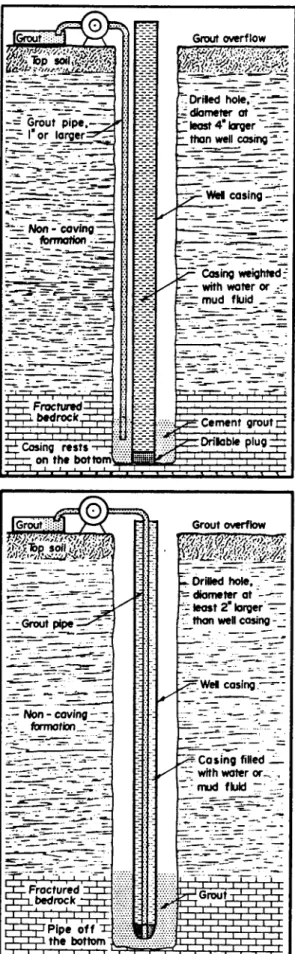
Figure 7: Grout Installation by Positive Placement Exterior Method ... 44
Figure 8: Grout Installation by Continuous Injection Method ... 44
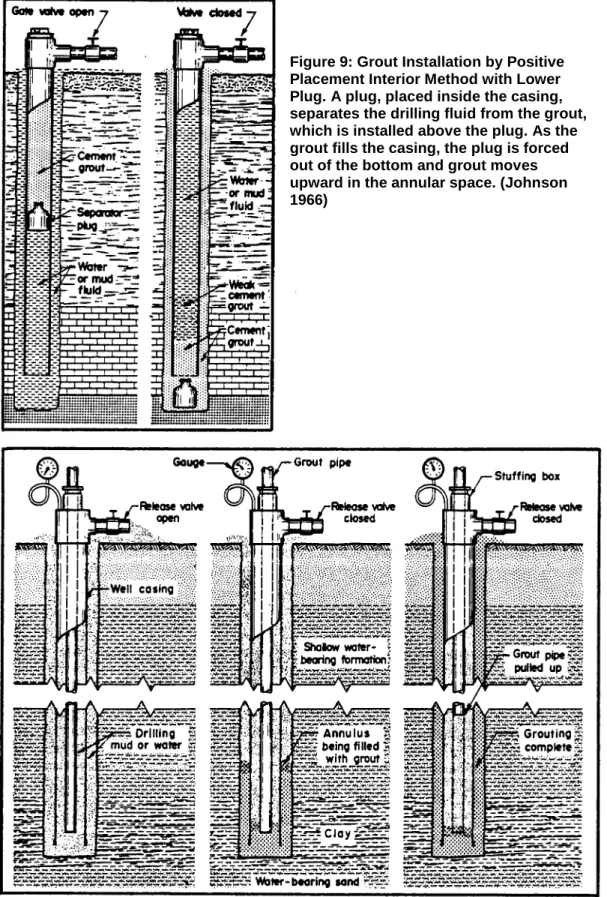
Figure 9: Grout Installation by Positive Placement Interior Method with Lower Plug ... 46
Figure 10: Grout Installation by Positive Placement Interior Method with Capped Casing... 46
Figure 11: Properly Vented and Sealed Well ... 49
Figure 12: Detail of Acceptable Well Cap... 49
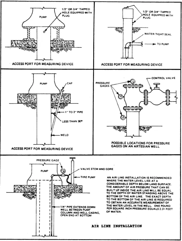
Figure 13: Suggested Methods for Installing Access Ports and Pressure Gages for Measuring Water Levels in Wells ... 50
Figure 14: Types of Pumps Commonly Used for Private Water Supply Wells ... 54
Figure 15: Principal Aquifers in Massachusetts... 62
TABLES
Table 1: Guidelines for the Construction of Drilled Wells ... 19 Table 2: Materials Standards for Steel Water Well Casing... 28 Table 3: Gallons of Water per Foot of Depth for Various Casing or Hole Diameters ... 41 Table 4: Flow Volumes in Gallons per Minute and Corresponding Flow Volumes in
Gallons per Day ... 41 Table 5: Summary of Pump Characteristics for Pumps Commonly Used for Private Water
Supply Wells ... 55 Table 6: Amount of Chlorine Compound Required to Produce a Chlorine Concentration
of 100 mg/L (for Well Diameters of One Foot or Less)... 59 Table 7: Amount of Chlorine Compound Required to Produce a Chlorine Concentration
of 100 mg/L (for Well Diameters of Two Feet or More) ... 59 Table 8: Recommended Analytes, Concentration Limits and Monitoring Frequency
for Private Wells ... 65 Table 9: Recommended Analytes, Concentration Limits and Monitoring Frequency
for Private Wells ... 67 Table 10: Recommended Analytes, Concentration Limits and Monitoring Frequency
for Private Wells ... 67 Table II Indicator Parameters ... 68
INTRODUCTION
A private water supply provides water for human consumption and consists of a system that has less than fifteen service connections and either (1) serves less than twenty-five individuals or (2) serves an average of twenty-five or more individuals daily for less than sixty days of the year. In the Commonwealth of Massachusetts over 500,000 people rely on private water systems to provide potable water because public water systems are not available to serve them.
The improper design, construction, repair, maintenance, or decommissioning of a private water supply system represents a potential hazard to public health and safety. In order to protect the health and general welfare of the citizens who depend on private water supply systems and to protect the groundwater resources of the Commonwealth so that the consuming public can be assured of potable water, it is necessary for regulators to know what constitutes a private water supply system and understand the measures that should be taken to protect the water supplied by the system.
The Private Well Guidelines and accompanying Model Board of Health Regulations for Private Wells were written primarily to assist Boards of Health but also to assist drillers by attempting to introduce some consistency regarding construction standards from town to town. The Private Well Guidelines also provides information useful to the private well owner, developers, and interested local officials.
The Model Board of Health Regulations for Private Wells provides general guidance because subsurface geology varies across the Commonwealth. Well construction and water quality concerns on Cape Cod, for example, differ substantially from those in western Massachusetts. The Private Well Guidelines, on the other hand, is a more comprehensive reference and provides detailed information regarding well construction in addition to discussion of issues concerning local groundwater protection and water quality. Because the Private Well Guidelines is intended as a reference, it was written with a built-in redundancy.
Although these guidelines contain information that is applicable to private water supply systems that derive water from surface water sources, the primary focus is on systems that utilize a well to obtain groundwater.
Household irrigation wells have become an issue recently because of the dramatic increase in water rates in parts of Massachusetts. The well construction requirements recommended in the Private Well Guidelines and the Model Board of Health Regulations for Private Wells could be applied to irrigation wells. However, if the wells are used strictly for irrigation, some of the recommended water quality testing requirements are too stringent.
Neither the Private Well Guidelines nor the Model Board of Health Regulations are a substitute for existing regulations and statutes.
SUMMARY OF LAWS AND REGULATIONS APPLICABLE TO PRIVATE WATER
SUPPLY SYSTEMS
Although the Commonwealth of Massachusetts does not have any statutes that specifically regulate private water supply systems, there are a number of laws that indirectly protect the quality of the water obtained from a private water system. This section summarizes existing laws and regulations that are applicable to private water supply systems. Regulations developed pursuant to the Massachusetts General Laws (MGL) are contained in the Code of Massachusetts Regulations (CMR) and can be purchased individually from the State House bookstores in Boston and Springfield.
STATE JURISDICTION Department of Conservation and Recreation
Chapter 21, Section 11 of the Massachusetts General Laws authorizes the Division of Water Supply Protection to "establish rules and regulations necessary for the proper administration of sections nine to sixteen, inclusive." Section 16requires any person engaged in the business of digging or drilling wells within the Commonwealth to register annually with the Division of Water Supply Protection. It also states that "within thirty days after completion of any well by digging or drilling, the person engaged in the business of digging or drilling wells shall submit a report to the Commission setting forth such information as may be required under said rules and regulations."
The regulations developed by the Division of Water Supply Protection pursuant to MGL Chapter 21, Sections 11 and 16 are contained in 313 CMR 3.00, "Water Well Diggers and Drillers Registration." These regulations (1) provide the criteria necessary for the registration of well diggers and drillers in the Commonwealth of Massachusetts, (2) establish the information that must be furnished as a prerequisite for registration, (3) establish the information that must be submitted to the Division of Water Supply Protection upon the completion of any well, and (4) set forth penalties, including revocation of registration, if a driller is found to be in noncompliance with state or town regulations.
Department of Environmental Protection
In Chapter 111 of the Massachusetts General Laws. the Department of Environmental Protection (DEP) is granted general responsibility and authority for protecting drinking water supplies within the Commonwealth. Specifically, Section 159confers upon the DEP "the general oversight and care" of all waters used by any municpality, institution, or person in the Commonwealth as a source of water supply. In Section 160, the DEP is authorized to "make rules and regulations and issue such orders as in its opinion may be necessary to prevent the pollution and to secure the sanitary protection of all such waters used as sources of water supply and to ensure the delivery of a fit and pure water supply to all consumers." Section 5G states that the DEP "may require by order a city, town, person or district maintaining a water supply to provide and operate such treatment facilities as are in its opinion necessary to insure the delivery of a safe water supply to all consumers."
In order to protect underground sources of drinking water as required in the Federal Safe Drinking Water Act, and pursuant to MGL Chapter III, Section 160 and MGL Chapter 21, Section 27, the DEPpromulgated 310 CMR 27.00, "Underground Water Resource Protection." These regulations prohibit the underground injection or disposal of hazardous wastes, and fluids having the potential to contaminate groundwater. In addition to the requirements provided in 310 CMR 27.00,MGL Chapter 21C, Section 5states that no person shall dispose of hazardous waste "in a manner which could endanger human health, safety or welfare, or the environment." In accordance with MGL Chapter 21C, Section 5 and 310 CMR 27.00, it is illegal to use a private water supply well, test hole, or dry or inadequate boring as a drain or disposal receptacle for any fluid or material including, but not limited to, sludge, solid waste or trash, and waste oil or other hazardous waste.
Chapter 21A, Section 13 of the Massachusetts General Laws requires the Commissioner of the DEP to adopt, and from time to time amend, regulations to be known as the State Environmental Code. More specifically, this code "shall deal with matters affecting the environment and the well being of the public of the Commonwealth." Section 13 also states that "local Boards of Health shall enforce said code in the same manner in which local health rules and regulations are enforced."
Pursuant to MGL Chapter 21A, Section 13, the DEP has promulgated 310 CMR 15.00, "Minimum Requirements for the Subsurface Disposal of Sanitary Sewage, State Environmental Code, Title 5." These regulations provide minimum standards for the location, design, construction, and operation of subsurface sanitary sewage disposal systems that discharge less than 10,000 gallons per day. The improper location, construction, or maintenance of a subsurface disposal system is of concern because it may adversely affect the quality of the water obtained from a nearby private water system.
It should be noted that the standards presented in the current version of Title 5 were developed primarily to protect public health from pathogenic viruses and bacteria. Local hydrogeologic conditions may require more stringent regulations. Pursuant to the Massachusetts General Laws Chapter 111, Section 31, local Boards of Health have the authority to adopt reasonable regulations as long as they are not less stringent than Title 5. On the other hand, a variance may be granted if (1) site specific conditions indicate that adequate protection can be provided without complying with the standards required by Title 5, and (2) Title 5 requirements would be a manifest injustice. Part II of Title 5 includes procedures for obtaining a variance. Generally, the local Board of Health may grant a variance but there are also specific requirements for which Title 5 expressly states that only the DEP (Waste Water Management Program) may grant variances. All variances granted by the local Board of Health must be sent to the DEP for review. The DEP has the authority to overrule the Board of Health's decision.
Chapter 131, Section 40 of the Massachusetts General Laws provides the DEP with the authority to promulgate regulations to protect wetland areas and confers upon the local Conservation Commission the responsibility for administering the law. Among the seven statutory interests are "public or private water supply" and "groundwater supply." Pursuant to MGL Chapter 131, Section 40, the DEP has promulgated 310 CMR 10.00, "Wetlands Protection." In accordance with MGL Chapter 131, Section 40 and 310 CMR 10.00, any person proposing construction or alteration of the land within 100 feet of a wetland or within the 100-year floodplain of any river or stream must apply to the local Conservation Commission for a Determination of Applicability. The Commission evaluates the impact prior to issuing a permit or denial and must ensure that "the capacity of an area to prevent pollution of groundwater shall not be adversely affected." The Commission's decision may be appealed to the Department of Environmental Protection.
The "Drinking Water Regulations," 310 CMR 22.00, promulgated by the DEP, pertain specifically to public water systems. However, they include water quality standards which can be used as guidelines for interpreting the results of analyses performed on water samples obtained from private water systems.
Department of Agricultural Resources, Pesticide Board
Pursuant to the Massachusetts General Laws Chapter 132B, the Pesticide Board promulgated 333 CMR 11.00, "Rights of Way Management." These regulations include procedures and requirements for marking and recording the location of private drinking water supplies which are within one hundred feet of a right-of-way. For private drinking water supplies that are marked and recorded in accordance with these regulations, no herbicide shall be applied within fifty feet of the supply, and no herbicide shall be applied between fifty feet and one hundred feet of the supply unless a minimum of twenty-four months shall elapse between applications, and herbicides shall be applied selectively by low pressure foliar techniques or stem application. Uniform standard signs have been produced and are currently available at the Department of Agricultural Resources.
Department of Public Health
Chapter 111, Section 127Aof the Massachusetts General Laws states that the Department of Public Health (DPH) "shall adopt, and may from time to time amend, public health regulations to be known as the State Sanitary Code." This code "shall deal with matters affecting the health and well-being of the public including, standards of fitness for human habitation."
MUNICIPAL JURISDICTION
Pursuant to the Massachusetts General Laws Chapter 40, section 54, which governs the powers and duties of cities and towns, "no building permit shall be issued for the construction of a building which would necessitate the use of water therein, unless a supply of water is available"from either a public or a private water system.
In accordance with the Massachusetts General Laws Chapter 111, Sections 122 and 122A, if the available supply of drinking water in any place of habitation is so unsafe or inadequate as to constitute a nuisance, the local Board of Health may issue a written order requiring the owner to discontinue use of the water supply, or, at his option, to provide a safe and adequate supply of drinking water.
Chapter 40, Section 21 of the Massachusetts General Laws grants municipalities the authority to adopt ordinances and bylaws which may, for example, require land owners to properly maintain their private water supply system and properly decommission abandoned water supply systems located on their property.
Chapter 83, Section 3 of the Massachusetts General Laws grants local Boards of Health the authority to require any landowner whose land abuts a public sewer system to hook into the public system at his or her own expense. Thus, the Board of Health can protect underground water supplies when a septic system threatens groundwater quality. Furthermore, the Board of Health's decision on such matters cannot be overridden by the Sewer Commissioners •
Chapter 111, Section 31 of the Massachusetts General Laws grants local Boards of Health broad authority to "make reasonable health regulations." Boards of Health are encouraged to adopt locally appropriate private well regulations which take into consideration local geology, land uses, and zoning regulations. It is the duty of local Boards of Health to monitor local conditions and create necessary regulations which address those conditions in order to protect public health. The following are examples of reasonable regulations that local Boards of Health may adopt under MGL Chapter 111, Section 31:
(1) setback distances required by Title 5 may be increased
(2) standards may be adopted governing the construction, alteration, maintenance, and decommissioning of private water supply systems
(3) periodic inspection and pumping of each septic system in the community may be required
(4) periodic testing of water from private water systems may be required
Adoption of health regulations by a Board of Health pursuant to MGL Chapter 111, Section 31, requires a majority vote of the Board and publication in a local newspaper. Pursuant to the Massachusetts General Laws, Chapter 21A, Section 8, regulations adopted under Chapter 111, Section 31, must be filed with the Department of Environmental Protection.
WATER SUPPLY SOURCES AND TYPES OF DOMESTIC WATER SUPPLY SYSTEMS
This section consists of the following subsections: Types of Domestic Water Supply Systems Groundwater Supplies
Surface Water Supplies
TYPES OF DOMESTIC WATER SUPPLY SYSTEMS
Domestic water supplies in Massachusetts are supplied by either groundwater or surface water. Groundwater supplies most often utilize water wells to draw water from unconsolidated (sand and gravel) deposits or from fractured bedrock. Springs, also supplied by groundwater, serve a small percentage of the population and may utilize a cistern for storing water. Surface water bodies such as lakes, ponds, streams, rivers and brooks supply a relatively small population when compared with households utilizing wells.
GROUNDWATER SUPPLIES This subsection consists of the following parts:
Water Wells Springs Water Wells
Subsurface geologic conditions throughout Massachusetts generally require one of two well construction techniques. A well drawing from a water bearing sand and gravel unit (overburden well) should be cased down to the most productive strata where an appropriately sized screen is installed. A well drawing water from bedrock fractures should be cased securely into the rock and the borehole in the rock is left open and unscreened and is used for storage.
There are several modifications of these two basic well types. Sandpoint wells, for example, consist of a screen coupled to a riser pipe which is pounded into a water bearing unit with tools that may be as simple as a sledge hammer. This type of well and installation technique is satisfactorily used in areas where the water table is close to the land surface and the ground being penetrated is sandy and devoid of cobbles, boulders and large gravel.
Dug wells, another modification of the basic overburden water well, are sometimes dug by hand but more often are constructed using a backhoe. These wells consist of large holes in the ground that extend below the water table and are lined with a large well screen, tile, or brick. Dug wells are generally constructed in areas where the water table is close to the land surface and where the geologic deposits are tight and compact, such as glacial till. Dug wells act as collection galleries or cisterns as groundwater seeps slowly into the collection area to the same level as the surrounding water table. Fluctuations, in the level of the water table may cause them to go dry and, unless they are adequately sealed to prevent infiltration of surface water, they are also vulnerable to contamination problems associated with the large annular space that typifies dug well construction.
The section entitled, "General Well Design and Construction" presents construction details for the aforementioned overburden wells and information pertaining to bedrock wells.
Springs
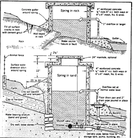
Springs emanating from rock or glacial till areas provide drinking water for a small percentage of the populace that depends on private sources. Frequently, larger transient populations stopping to fill water jugs at roadside springs require evaluating the source as though it were a public water supply. Springs are frequently connected and piped to concrete galleries that allow spillover to be piped elsewhere. Because springs may flow some distance as surface water and their collection systems are frequently open, they can easily become contaminated, and should be sampled regularly. Spring boxes or spring houses may add some sanitary protection to a spring. If constructed properly (Figure 1), they provide a sanitized discharge point and isolate the spring from contamination that could be introduced at the land surface.
Figure 1: Properly Constructed Springs (Salvato, 1958)
SURFACE WATER SUPPLIES
Surface waters are rarely used for private drinking water supplies in Massachusetts. Because of their exposure to the air and a lack of filtering media, surface waters often experience water quality problems not associated with groundwater sources and frequently require some form of treatment in order to meet aesthetic and public health concerns. Algal blooms, bacterial contamination, turbidity, sedimentation and temperature fluctuations are some of the water quality problems associated with surface water supplies.
Surface waters are not recommended for use as a domestic drinking water supply. Homeowners using drinking water derived from private surface water sources should exercise caution and maintain rigorous and regular water quality sampling and testing practices.
PERMITS AND REPORTS
This section consists of the following subsections: Permits Reports
PERMITS This subsection consists of the following parts.
Required Registration of Well Diggers and Drillers Required Building Permit
Recommended Permits
Required Registration of Well Diggers and Drillers
Chapter 21, Section 16 of the Massachusetts General Laws requires any person engaged in the business of digging or drilling wells within the Commonwealth to register annually with the Division of Water Supply Protection of the Department of Conservation and Recreation. In addition, MGL Chapter 21, Section II, authorizes the Division of Water Supply Protection to establish regulations necessary for the proper administration of the law cited above. The regulations developed by the Division of Water Supply Protection are contained in 313 CMR 3.00, "Water Well Diggers and Drillers Registration." These regulations (1) provide the criteria necessary for the registration of well diggers and drillers in the Commonwealth of Massachusetts, (2) establish the information that must be furnished as a prerequisite for registration, (3) establish the information that must be submitted to the Division of Water Supply Protection upon the completion of any well, and (4) set forth penalties, including revocation of registration, if a driller is found to be in noncompliance with state or town regulations.
Accordingly, any person in the business of digging or drilling who constructs, repairs, or alters a private well must be registered with the Division of Water Supply Protection at the time the work is performed. In addition, any person who decommissions (plugs) an abandoned well must have a valid Division of Water Supply Protection registration.
Required Building Permit
Pursuant to MGL Chapter 40, Section 54, which governs the powers and duties of cities and towns, "no building permit shall be issued for the construction of a building which would necessitate the use of water therein, unless a supply of water is available" from either a public or a private water system.
Recommended Permits
Requiring permits for activities related to private wells can provide information necessary for the protection of public health. In addition, local water supply resources can be properly evaluated and protected only when information pertaining to the use and quality of these resources is available. Chapter 111, Section 31 of the Massachusetts General Laws grants local Boards of Health broad authority to "make reasonable health regulations." Accordingly, various permit requirements may be established for activities related to private wells.
It is recommended that local Boards of Health establish, for example, requirements for the following:
(1) private well construction permit (2) plumbing permit
(3) private well alteration permit (4) renewable private well use permit
(5) permit for decommissioning (plugging) abandoned wells, test holes, and dry or inadequate borings
A private well construction permit allows the regulating agency to identify well sites that may require special water quality monitoring or may not be acceptable due to water quality problems that have occurred in the vicinity of the site. It is recommended that the application for a well construction permit be submitted by the property owner or his designated representative to the Board of Health on a form furnished by the Board. The application should include:
(1) the property owner's name and address
(2) the well driller's name and proof of valid state registration
(3) a plan with a specified scale, signed by a registered surveyor or engineer, showing the location of the proposed well in relation to existing or proposed above or below ground structures
(4) a description and location of visible prior and current land uses within two-hundred (200) feet of the proposed well location, which represent a potential source of contamination, including but not limited to the following:
(a) existing and proposed structures (b) subsurface sewage disposal systems (c) subsurface fuel storage tanks
(d) public ways
(e) utility rights-of-way
(f) any other potential sources of pollution
(5) proof that the owner of any property abutting the applicant's property has been notified of the applicant's intention to install a well
(6) a permit fee
A plumbing permit can ensure that only qualified persons connect a private well to the distribution system of the residence. A private well use permit allows the Board or Health to identify wells which may be threatened by contamination; can assist with the establishment of a local water quality monitoring program, and aids in identifying abandoned wells which should be plugged.
It should be the responsibility of the landowner, or the landowner's agent, to provide any and all permits that are required by the local Board of Health.
REPORTS This subsection consists of the following parts.
Well Completion Report Required by the Division of Water Supply Protection Recommended Pumping Test Report
Recommended Water Quality Report Recommended Decommissioning Report
Well Completion Report Required bv the Division of Water Supply Protection
Requirements of 313 CMR 3.00 state, in part, that within thirty (30) days after completion of any well (productive or nonproductive), or after plugging of an abandoned well, a registered well driller shall submit to the Division of Water Supply Protection, with a copy to the local Board of Health, a report containing:
(1) the name and address of the owner of the well
(2) the geographic location of the well (this shall be given accurately to enable easy plotting on a U. S. Geological Survey Topographic (1:25,000 scale) Map)
(3) work performed (i.e., new installation, repair, abandonment)
(4) proposed use of well ( if proposed use as public water supply other than municipal , describe public water supply classification under “other”)
(5) drilling method
(6) drilling log describing the material penetrated, including: (a) well depth
(b) depth to refusal or bedrock (c) bedrock type
(7) site sketch
(8) date drilling completed (9) casing type, size and length (10) protective well seal
(11) well screen type, slot size, length, and depth at which bottom of well screen is set (12) description of filter pack and grouting materials used
(13) method of plugging an abandoned well (14) method used to test well yield including:
(a) date and length of time (in hours and mins) well pumped (b) drawdown and recovery
(c) well yield (15) static water level
(16) pump description, depth and installer
Well Completion Report forms are available from the Division of Water Supply Protection. Any driller who files a false report is subject to revocation of registration.
Figure2: Well Completion Report Required by the Division of Water Supply Protection. Completed in triplicate, the driller retains the first page and is required to submit the second and third pages to the local Board of Health and the Division of Water Supply Protection, respectively.
Recommended Pumping Test Report
All pumping test data should be recorded and included in a report that the contractor should submit to the well owner. If the well driller performs the pumping test, a copy of the pumping test report should be appended to the Well Completion Report that is submitted to the local Board of Health and the Division of Water Supply Protection.
The Pumping Test Report should include, but not be limited to, the following information: (1) name and address of the well owner
(2) well location, referenced to at least two permanent structures or landmarks (3) date the pumping test was performed
(4) depth at which the pump was set for the test (5) location of the discharge line
(6) the static water level immediately before pumping commenced
(7) the discharge rate and, if applicable, the time the discharge rate changed (8) pumping water levels and respective times after pumping commenced (9) the maximum drawdown during the test
(10) the duration of the test, including both: a) the pumping time, and
b) the recovery time during which measurements were taken
(11) recovery water levels and respective times after cessation of pumping (12) reference point used for all measurements
Recommended Water Quality Report
It is recommended that the local Board of Health require the well owner to submit to the Board a Water Quality Report anytime a private water supply is tested. The report should include: (1) Name, address and phone number or other contact information for the individual who performed the sampling (i.e., BOH member, BOH agent, lab personnel, well owner, well owner's agent);
(2) where in the system the sample was obtained (point-of-use or point-of-entry) and, if sampled, at the point-of-use, whether or not the system was flushed prior to sampling;
(3) type of water treatment used (chemical or special device e.g., disinfection, reverse osmosis unit, filter, etc.), if applicable;
(4) date and time of sample collection;
(5) date and time sample received by the laboratory; (6) a copy of the laboratory's test results; and, (7) a copy of the Chain of Custody.
Results that indicate no contamination are as important as those that indicate water quality problems because these results provide background data in case of future contamination. A complete record of all testing results is also useful when designing local water quality testing programs.
Recommended Decommissioning Report
Within 30 days following the completion of the plugging procedure, the registered well driller who plugged the abandoned well, test hole, or dry or inadequate boring must submit a Well Completion Report to the Division of Water Supply Protection and should submit a Decommissioning Report to the owner of the property where the well, test hole, or boring is located. It is recommended that the local Board of Health require that the property owner file a copy of the Decommissioning Report with the appropriate Registry of Deeds or Land Court as part of the chain-of -title. Another copy of the Decommissioning Report should be submitted to the Board of Health. It is recommended that the copy submitted to the Board of Health include the Book and Page reference and the name of the Registry of Deeds where the report was filed or, in the case of registered land, the appropriate Land Court reference.
The following information should, when available, be included in the Decommissioning Report:
(1) name and address of the property owner
(2) name and address of the registered well driller who performed the plugging (3) reason for abandonment
(4) location of the well, test hole, or boring referenced to at least two permanent structures or, when possible, location coordinates determined by a registered land surveyor or registered civil engineer
(5) all information known about the well, test hole, or boring including but not limited to: (a) depth
(b) diameter (c) type of casing
(6) calculations made to determine the volume of the well, test hole, or boring (7) static water level before plugging
(8) types of plugging material used, including mix specifications (9) quantity of each type of plugging material used
(10) description of the plugging procedure including, but not limited to, notes regarding: (a) removal of pump and other obstructions
(b) removal of screen
(c) perforation or removal of casing
(d) method(s) used to place plugging material (s)
(11) a copy of the original well driller's report, when available
(12) a copy of the abandonment permit, if a permit is required by the local Board of Health
WELL LOCATION
This section consists of the following subsections: General Considerations
Relation to Property Lines and Buildings Relation to Gas Lines and Overhead Relation to Surface Water and Wetlands
Requirements of the State Environmental Code, Title 5 Additional Considerations
GENERAL CONSIDERATIONS
Any person intending to have a private well constructed should identify all potential sources of contamination which exist within 200 feet of the site. Where possible, a well should be located upgradient of all potential sources of contamination and should be as far removed from potential sources of contamination as the general layout of the premises and surroundings permit. Additionally, every well should be located so that it will be reasonably accessible with proper equipment for repair, maintenance, testing, and inspection.
The well should be completed in a water bearing formation that will produce the required quantity of water under normal operating conditions without adversely impacting adjacent wells. Water quantity considerations are discussed in the section entitled "Water Quantity (Pumping Test)" (page 47).
RELATION TO PROPERTY LINES AND BUILDINGS
Private water supply wells should be located at least ten feet from all property lines. The center line of a well should, if extended vertically, clear any projection from an adjacent structure by at least five feet.
RELATION TO GAS LINES AND OVERHEAD POWER LINES
A well should be located a minimum of 15 feet from a gas line or overhead electric distribution line and should be at least 25 feet from an electric transmission line which is in excess of 50 kV. When subsurface utilities are already in place. Dig Safe should be contacted at least three days before drilling begins.
RELATION TO ROADS AND RIGHTS-OF-WAY
All private water supply wells should be located at a minimum of 25 feet from the normal driving surface of any roadway or a minimum of 15 feet from the road right-of-way, whichever is greater. Additionally, it should be noted that the "Rights-of-Way Management" regulations (333 CMR 11.00) include procedures and requirements for marking and recording the location of private drinking water supplies which are within one hundred feet of any right-of-way. Private drinking water supplies that are marked and recorded in accordance with the aforementioned regulations are protected by restrictions on the use of herbicides for maintaining rights-of-way. Uniform standard signs for marking water supplies have been produced and are currently available from the Department of Agricultural Resources.
RELATION TO SURFACE WATER AND WETLANDS
Private water supply wells should be located at least 25 feet, laterally, from the normal high water mark of any lake, pond, river, stream, ditch, or slough. Additionally, it should be noted that land use within 100 feet of a wetland or within the 100-year floodplain of any river or stream is regulated under Chapter 131, Section 40, of the Massachusetts General Laws and 310 CMR 10.00, "Wetlands Protection." Prior to constructing a private water supply in these areas, approval must be obtained from the local Conservation Commission. Where possible, private water systems should be located in areas above the 100-year floodplain. When a well must be located in an area subject to flooding, special protection should be provided, as is discussed in the section entitled "Wellhead Completion" (page 59).
REQUIREMENTS OF THE STATE ENVIRONMENTAL CODE. TITLE 5
Pursuant to Chapter 21, Section 13, of the Massachusetts General Laws, the Department of Environmental Protection promulgated 310 CMR 15.00, "Minimum Requirements for the Subsurface Disposal of Sanitary Sewage, State Environmental Code, Title 5." These regulations provide minimum standards for the location, design, construction, and operation of subsurface sanitary sewage disposal systems that discharge less than 10,000 gallons per day.
It should be noted that the standards presented in the current version of Title 5 were developed primarily to protect public health against pathogenic viruses and bacteria. Local hydrogeologic conditions may require more stringent regulations. Boards of Health have the authority to strengthen Title 5 by implementing appropriate and reasonable local regulations.
Under Title 5, surface water supplies (reservoirs) or tributaries to reservoirs, including open and subsurface drains must be located a minimum of:
(1) 50 feet from a septic tank (2) 100 feet from a leaching facility (3) 100 feet from a privy
According to Title 5, these distances "shall be measured from the average of the mean annual flood elevation in inland areas and from mean high water in coastal areas." It should also be noted that for (2) and (3), above. Title 5 states that "100 feet is a minimum acceptable distance and no variance shall be granted for a lesser distance except with prior written approval of the Department of Environmental Protection”.
Title 5 also requires that a well or suction line or well be located a minimum of:
(1) 10 feet from a building sewer constructed of durable corrosion resistant material with watertight joints, or 50 feet from a building sewer constructed of any other type of pipe
(2) 50 feet from a septic tank (3) 100 feet from a leaching field (4) 100 feet from a privy
For (3) and (4) above, Title 5 notes that "100 feet is a minimum acceptable distance and no variance shall be granted for a lesser distance except with prior written approval of the Department of Environmental Protection."
In regard to pressurized water supply lines. Title 5 states that "it is suggested that the disposal facilities be installed at least 10 feet from and 18 inches below water supply lines. Wherever sewer lines must cross water supply lines, both pipes shall be constructed of class 150 pressure pipe and should be pressure tested to assure watertightness."
Part II of Title 5 includes procedures for obtaining a variance. Generally, the local Board of Health may grant a variance but there are also specific requirements for which Title 5 expressly states that only the Department of Environmental Protection (Waste Water Management Program) may grant variances. In order to grant a variance, however, it is important to have site specific hydrogeologic information submitted which documents that adequate protection can be provided without complying with the standards required by Title 5. All variances granted by the local Board of Health must be sent to the DEP for review. The DEP has the authority to overrule the Board of Health's decision.
ADDITIONAL CONSIDERATIONS
Several states have regulations pertaining to the location of a well in relation to a number of specified potential sources of contamination. The following examples indicate the range of minimum lateral distances required: (1) petroleum storage tanks; 20 feet to 50 feet, (2) stables, barnyards, feedlots, manure piles, and manure storage tanks; 50 feet to 100 feet. These distances may be used as guidance for locating a well but it is not recommended that they be adopted as regulations because the potential hazard to a well depends on site specific hydrogeology. For example, consideration should be given to the direction of ground-water flow and the location of any groundwater discharge to a surface water body. Where possible, wells should be located upgradient of potential sources of contamination. Wells should not be located between a potential source of contamination and an area where groundwater discharges to the land surface. Other considerations for locating a well include the permeability, transmissivity, and composition of the subsurface geologic materials. It should be kept in mind that contaminants can be transported great distances through fractured bedrock and groundwater flow in the overburden may not be in the same direction as in the bedrock.
GENERAL WELL DESIGN AND CONSTRUCTION
This section consists of the following subsections: General Considerations Well Design
Cleaning and Disinfection of Drilling Equipment Drilling Fluids
Temporary Cover
GENERAL CONSIDERATIONS
This subsection is a compilation of miscellaneous items that should be considered when designing and constructing a private water supply well.
All private water supply wells should be designed so that:
(1) the materials used for the permanent construction are durable in the specific hydrogeologic environment that occurs at the well site; and
(2) no unsealed openings will be left around the well that could conduct surface water or contaminated groundwater vertically to the intake portion of the well or transfer water from one formation to another.
In addition, permanent construction materials should not impart toxic substances, taste, odors, or bacterial contamination to the water in the well. It should also be noted that lead packers should not be used in the construction of any water supply wells.
The driller should operate all equipment according to generally accepted standards in the industry and should take appropriate precautions to prevent damage, injury or other loss to persons and property at the drilling site.
A well under construction should be protected so that surface wash is diverted away from the construction area and contaminants do not enter the well through the opening or by seepage through the ground surface, in addition, workers employed at the construction site should exercise caution in the disposal of wastes and in handling construction materials so as to avoid contamination of the well and the aquifer. The contractor should also take reasonable precautions to prevent either tampering with the well or the entrance of foreign material into the well during overnight shutdowns and other times when the contractor is away from the site.
During drilling, it is recommended that formation samples be taken at each change in formation. The sample depth and composition should be recorded in the driller's log. Well yield should be measured and recorded at least every 50 feet during drilling in order to prevent drilling to excessive depths.
All water used for drilling, development, or rehabilitation should be obtained from a source which will not result in contamination of the well or the water bearing zones penetrated by the well. Water should be conveyed in clean sanitary containers or water lines and should be chlorinated to an initial concentration between 50 mg/l and 100 mg/l and a free-chlorine residual of 10 mg/l should be maintained. Water from water bodies such as wetlands, swamps, and ponds should not be used.
All wells, including those that have been hydrofractured, should be developed in order to remove fine materials introduced into the pore spaces or fractures during construction. One or more of the following methods should be used for development: overpumping, backwashing, surging, jetting, air-lift pumping.
The completed well should be sufficiently straight so that there will be no interference with installation, alignment, operation or future removal of the permanent well pump.
Any work involving the connection of the private well to the distribution system of the residence must conform to the local plumbing code. All electrical connections between the well and the pump controls and all piping between the well and the storage and/or pressure tank in the house should be made by a pump installer or registered well driller. It is recommended that the pump installer be certified by the National Water Well Association for the installation of domestic pumps (1 to 3 hp).
WELL DESIGN This subsection consists of the following parts:
Drilled Wells
Nonflowing Artesian Wells Sandpoint Wells
Dug Wells Drilled Wells
Several drilling methods are used for constructing private water supply wells. The efficiency of each drilling method depends to a great extent on the type of geologic formation being drilled. Other factors that affect the efficiency of a particular drilling method include the experience of the driller, the presence of geologic anomalies, and the hydraulic head of the aquifer or aquifers penetrated.
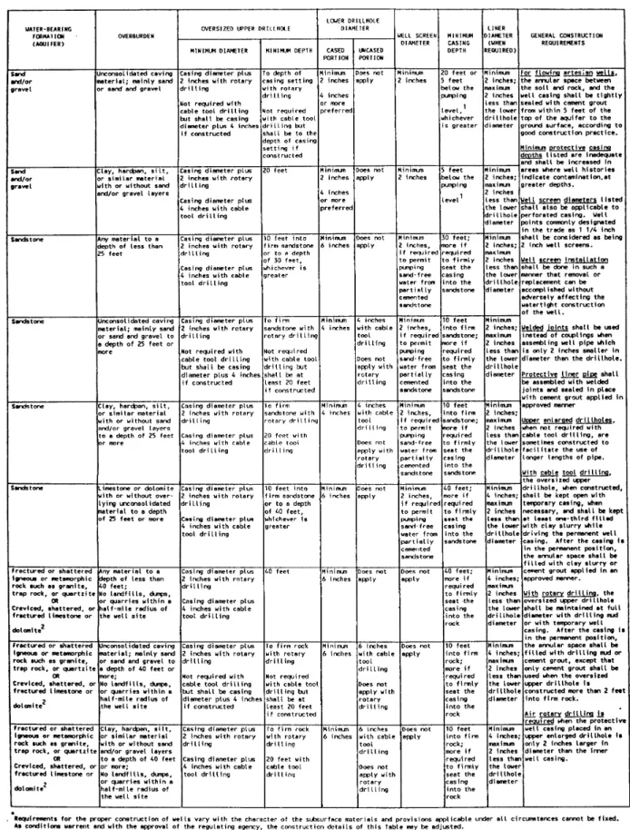
The specific design of a well depends on the subsurface geology at the well site and the drilling method used. Table I provides an example of some of the requirements for drilled water supply wells used by the State of Wisconsin (1985) and recommended by the U.S. Department of Health, Education, and Welfare (1965).
Nonflowing Artesian Wells
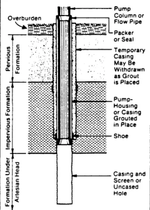
The following methods of construction (Figure 3) are recommended for wells completed in nonflowing artesian aquifers:
(1) Extend an oversized drillhole into but not through the confining layer, being sure that no water flows from the artesian zone into the drillhole
(2)
Install an unperforated, watertight protective casing with the drive shoe(3) Seal the annular space between the casing and the drillhole with neat cement grout or sand cement grout applied from the bottom of the drillhole upward to a depth which will adequately prevent subsurface leakage from the artesian zone
Figure 3: Appropriate
Constuction for a Nonflowing Artesian Well (AWWA, 1984)
(4) After the grout has set completely, extend the drillhole into the artesian zone being sure to packer that provides a watertight seal between the and outer casings
(5) Complete the well as recommended in the section entitled "Wellhead Completion" (page 47)
(6) If leakage occurs around the well casing or adjacent to the well, the well should be recompleted using additional casing, seals, and/or packers as necessary to completely eliminate leakage
Flowing artesian wells should be equipped with a shutoff valve and backflow preventer so that the flow of water can be stopped completely when the well is not in use. Watertight pump connections or a receiving reservoir set at an elevation corresponding to the artesian head may also be used. However, there should never be a direct connection between the discharge pipe and a receiving reservoir or any other potential source of contamination. The well owner should adjust the valves so that the quantity of water flowing from the well is adequate for ordinary use and no excess water is being wasted.
Sandpoint Wells
This part consists of the following subparts: General Considerations Installation
General Considerations
Sandpoint wells are installed only in unconsolidated formations which do not contain numerous cobbles and boulders. The maximum depth that can be attained with a sandpoint well is approximately 30 feet, if the well point is hand driven. If the well is jetted or if the well point is driven by a mechanical driver, however, a depth of 50 feet or more may be attained.
Sandpoint wells are commonly 1 1/4 to 2 inches in diameter. It is recommended that neither the well screen nor the well casing be less than 1 1/4 inch in diameter. In selecting casing, consideration should be given to the depth of the static water table, being sure to account for seasonal fluctuations. When the static water level is within about 15 feet of the land surface, the well can be pumped by suction lift and the casing diameter can be as little as 1 1/4 inch in diameter. However, if the static water level is deeper than about 15 feet, the well must be pumped by a jet pump or a cylinder pump.
All well casing should be unperforated and water tight. Under no circumstances should thermoplastic well casing be used for a driven well.
The depth of a sandpoint well should be sufficient to prevent breaking suction when pumping the well at a rate 50% greater than the capacity of the permanent pump. When possible, the casing should extend to a minimum depth of 20 feet or 10 feet below the pumping level, whichever is greater. The "pumping level" is the maximum drawdown occurring in the well during pumping, determined to the best knowledge of the water well contractor, accounting for usual seasonal fluctuations of the static water level and drawdown level.
Installation
The following procedure is recommended for installing hand driven sandpoint wells: (1) Use a hand auger or a post hole digger and bore a hole
which is:
(a) slightly larger in diameter than the wellpoint, (b) vertical, and
(c) a minimum of 3 feet deep but as deep as possible.
(2) Using pipe-thread compound approved by the National Sanitation Foundation for water wells and couplings with recessed ends and tapered threads, either:
(a) connect the wellpoint to a 5-foot length of well casing or to a string of well casing; or
(b) connect the wellpoint to a coupling and place the wellpoint into a 5-foot length of oversized casing, attaching additional lengths of casing if desired.
Oversized casing protects the well screen and is used most often when driving deep wells. (3) Place the wellpoint-casing assembly into the bored hole and backfill the hole. (4) Attach an iron drive cap to the top of the casing.
(5) Drive the casing into the ground either by hand, using a weighted pipe similar to a fence post driver, or by using a mechanical driver. Add additional lengths of casing as needed until the desired depth has been attained.
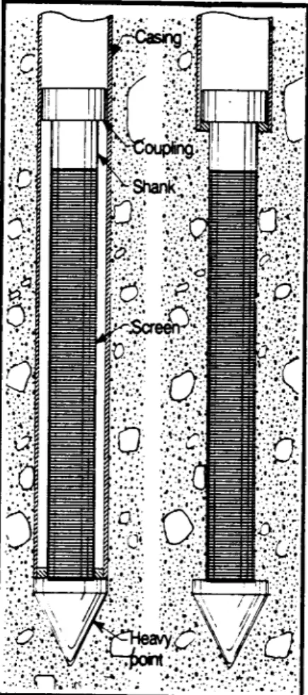
(6) When oversized casing is used, expose the well screen at the predetermined depth either by driving it with an inner casing inserted through the oversized casing or by pulling back the oversized casing (Figure 4).
(7)Protect against freezing by means of a pitless adapter or an enclosing casing pipe. Dug Wells
This part consists of the following subparts: General Considerations
Construction of Standard Dug Wells
Buried Slab Type Construction of Dug Wells
General Considerations
A dug well is a shallow well that is generally 20 to 35 feet deep and three to five feet in diameter. Dug wells can be excavated by hand but, due to federal occupational-safety laws, are more often excavated using a backhoe. Dug wells are generally less reliable than drilled wells and should be constructed only where hydrogeologic conditions preclude the construction of a satisfactory drilled well.
Although the relatively large diameter of a dug well provides a large water storage capacity, these wells often go dry when the water table drops during periods of drought. Additionally, since
it is more difficult to dig below the water table, it is recommended that construction of a dug well take place during the months of August through October when the elevation of the water table tends to be at its annual low.
Due to the relatively large diameter of a dug well, concrete casing, also called curbing, is used instead of steel casing. When concrete is used, it consists of either precast concrete pipe or it is poured-in-place. The wall thickness of precast concrete pipe should be a minimum of three inches thick and poured-in-place concrete should have a wall thickness equal to at least six inches. Recommended specifications for concrete casing are discussed in the section entitled "Well Casing" (page 33).
The casing of a dug well should be watertight to the depth of the production aquifer or to a depth of 20 feet below the preexisting ground surface, whichever is greater. The upper terminus of the well casing should extend 12 inches above the pre-existing ground surface or two feet above the highest recorded flood, whichever is greater. All above-grade and below-grade connections should be watertight.
When precast concrete pipe is used to case a dug well, the excavation should be at least four inches larger than the outside diameter of the casing. The annular space between the face of the excavation and the casing should be sealed with neat cement grout or sand cement grout to a depth below the local frost line.
The intake portion of a dug well below the watertight casing should consist of perforated casing or a loosely laid wall of stone, concrete block, or brick. It must be of adequate strength to withstand any external pressure to which it may be subjected and must be seated firmly enough to prevent settling.
Dug wells are constructed using either a standard type design or a buried slab design. Specifics pertaining to these two types of design are discussed below.
Construction of Standard Dug Wells
The design and recommended construction specifications for standard dug wells are illustrated in Figure 5. When standard construction is used, the well should be provided with a cover made of reinforced concrete that is at least four inches thick. The cover should rest on and overlap the outer edge of the well casing by at least two inches. The cover should be constructed without joints. Adequately sized pipe sleeve required to accommodate the type of pump and pump piping proposed for the well should be cast in place when the cover is fabricated. The top of the cover should be sloped so that water drains away from the sleeve.
Figure 4: Sandpoint Installed with Protective Oversized Casing. During Driving , the casing pushed a special heavy duty drive point downward while the casing protects the screened portion of the wellpoint. The screen is exposed at the predetermined depth either by driving it with an inner casing inserted through the oversized casing or pulling back the oversized casing (Driscoll, 1986).
Figure 5: Construction Details a for Standard Dug Well (Salvato, 1958).
A manhole, if installed, should be provided with a curb which extends at least two inches above the top of the cover and is cast in place when the cover is fabricated. The manhole should be equipped with an overlapping cover, the sides of which extend downward around the curb at least one and one-half inches. The joint between the curbing and the cover of the manhole should be made watertight with a plastic sealing compound and the manhole cover should be locked or bolted in place
Buried Slab Type Construction of Dug Wells
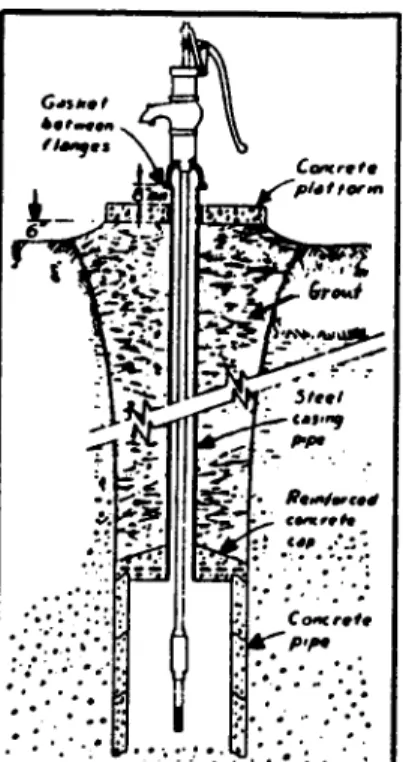
Buried slab construction of a dug well (Figure 6) utilizes a steel reinforced concrete slab which is placed over and grouted to the lower portion of the well casing. The slab, which permits the use of casing with a substantially smaller diameter for the upper portion of the well, should be at least three inches thick and, when possible, should be placed at a depth equal to or greater than 20 ft. below the preexisting ground surface. The upper well casing should be a minimum of four inches in diameter and should be either firmly imbedded in the, slab or connected to a pipe cast in the slab. The seal between the upper well casing and the slab should be watertight and the annular space between the casing and the excavation should be grouted with neat cement grout or sand cement grout.
If the pump is to be installed over the well, a concrete platform should be provided. The platform should be equipped with an adequately sized cast-in-place pipe sleeve and the top of the platform should be sloped away from the sleeve in all directions.
CLEANING AND DISINFECTION OF DRILLING EQUIPMENT In order to prevent the transfer of microbiological and chemical contaminants from previous drilling operations to uncontaminated groundwater, all drilling equipment, including pumps and down hole tools, should be cleaned and disinfected prior to drilling any new well or test hole. Disinfection of drilling equipment may be accomplished with a solution having a chlorine concentration equal to 100 mg/l. Other solutions used to decontaminate drilling equipment include trisodium phosphate, sodium carbonate, and sodium bicarbonate. A 10 percent aqueous solution of trisodium phosphate is good as a rinsing solution or detergent. A 10-20 percent aqueous solution of sodium carbonate is effective for cleaning inorganic acids from equipment. Sodium bicarbonate in a 5-15 percent aqueous solution can effectively clean both acids and bases from drilling equipment,
DRILLING FLUIDS Drilling fluids are used with rotary drilling to:
(1) lift the cuttings from the bottom of the hole and carry them to a settling pit (2) stabilize the borehole wall to prevent caving
(3) lubricate the bit, bearings, mud pump, and drill pipe (4) control fluid loss by sealing the borehole wall (5) facilitate the removal of cuttings into a settling pit
Drilling fluids used in the construction of water wells are either water or air based. The major types of water based drilling fluids consist of:
(1) clean, fresh water, (2) water with clay additives,
(3) water with polymeric additives, or (4) water with clay and polymeric additives. The primary types of air based drilling fluids consist of:
(1) dry air,
(2) mist: droplets of water entrained in the airstream, (3) foam:air bubbles surrounded by a film of water
containing a foam-stabilizing surfactant (soap), or
(4) stiff foam: foam containing film-strengthening materials such as polymers and bentonite.
Figure 6: Dug Well Constructed with a
As indicated above, the primary drilling fluid additives are clays, polymers, and surfactants. Other additives which may be used include flocculants, dispersants (thinning agents), weighting materials, corrosion inhibitors, filtrate reducers, nontoxic lubricants, preservatives, lost-circulation materials, and bacteriacides.
The specific composition of the drilling fluid used depends primarily on the type of subsurface materials expected and the drilling equipment available. Availability of water at the drilling site and the experience of the drilling crew are also factors that affect drilling fluid selection. In general, water based drilling fluids with clay or polymeric additives are typically used for drilling unconsolidated formations while air based fluids are used for drilling well-consolidated or semiwell-consolidated rocks and sediment.
Regardless of the specific composition, all drilling fluids must be nontoxic. Drilling fluid additives should be stored in clean containers and should be free of material that may adversely affect the well, the aquifer, or the quality of the water to be pumped from the well. In addition, surfactants should be biodegradable. Although biodegradable organic polymers, such as guar gum, are commonly used as drilling fluid additives, it should be noted that their use has resulted in persistent microbiological contamination of groundwater supplies. Consequently, the use of biodegradable organic polymers should, when possible, be avoided.
It is recommended that all water used to mix a drilling fluid, as well as any makeup water added, be chlorinated. Depending on the particular additives used for the drilling fluid, the mix water should be chlorinated to a concentration between 50 mg/l and 100 mg/l. The latter concentration is recommended, for example, when organic biodegradable polymers are used in the drilling fluid. In addition, a free-chlorine residual of approximately 10 mg/l should be maintained in the fluid during drilling. This concentration may be easily determined with chlorine paper and should be checked periodically. Chlorination is important because it retards the growth of bacteria introduced into the well during drilling procedures.
It should also be noted that mix water should never be taken from wetlands, swamps, small lakes, or other similar surface waters because these water supplies often contain both pathogenic bacteria and iron bacteria. Iron bacteria are of concern because their growth in a well can substantially reduce the well yield and can degrade the quality of the water obtained from the well.
TEMPORARY COVER
When there is an interruption in work during construction or alteration of a well due to such factors as overnight shutdown, inclement weather, time required for the setting of sealing materials, testing, or a delay prior to installation of pumping equipment, the contractor should protect the well in such a manner as to effectively prevent tampering with the well or the entrance of foreign matter into it.
During interruptions of one week or longer, a semi-permanent watertight cover should be installed. For a well cased with steel, the semi-permanent cover should consist of a steel or cast iron cap, of at least three-sixteenths of an inch in thickness, tack welded to the top of the casing.
WELL CASING
This section consists of the following subsections: General Considerations Steel Water Well Casing
Thermoplastic Water Well Casing Concrete Water Well Casing
GENERAL CONSIDERATIONS
Well casing, also called riser pipe, serves both as a housing for the pumping equipment and as a vertical conduit for the water pumped from the aquifer. Although the well casing generally extends from the intake portion of the well upward to the land surface, the lower portion of a drillhole may be left uncased when the well is completed in competent bedrock.
Private water supply wells should be constructed using steel, thermoplastic, or concrete well casing. The casing should be of adequate strength and durability to withstand anticipated formation and hydrostatic pressures; the forces imposed on it during installation; and the corrosive effects of the local hydrogeologic environment. The casing material used depends on the drilling method, the depth and diameter of the well, the character of the subsurface materials, and local groundwater quality. Thermoplastic casing, for example, is resistant to corrosive groundwater and acid treatment but it is not as strong as steel casing. Steel casing, on the other hand, should always be used when the casing is driven with a cable tool drilling rig or when the casing is installed in an open drillhole in which formation materials may suddenly collapse against the casing.
All casing used in the construction of private water supply wells should be free of pits, breaks, gouges, deep scratches, and other defects. If previously used casing is installed, it should not only be free of defects, as mentioned above, but should also have been used only in a water well test hole, or a dry or inadequate boring. Additionally, the casing should have been salvaged within 30 days of the original installation and should be decontaminated and disinfected prior to installation.
The diameter of the well casing must provide enough clearance for proper installation and operation of the well pump.
Installation of water well casing should be done in a manner that does not alter the shape, size, or strength of the casing and does not damage any of the joints connecting sections of the casing. Upon completion of the installation procedure, the entire length of the casing above the intake should be water tight.
STEEL WATER WELL CASING This subsection consists of the following parts:
Materials Standards
Marking of Steel Water Well Casing Methods of Joining Steel Casing Installation of Steel Casing
Materials Standards
Due to the great variety of tubular steel products available, there are a number of different standards for materials considered acceptable for use as water well casing. All steel casing used in the construction of private water supply wells should consist of schedule 40 pipe that complies with one of the materials standards approved by the American Water Works Association (Table 2). In all cases, the wall thickness should be sufficient to withstand hydraulic loading if the casing is pumped dry and should have a collapse strength greater than one pound per square inch for every 2.31 feet of depth beneath the top of the aquifer (Driscoll, 1986).
Marking of Steel Water Well Casing
Each length of casing shall be legibly marked in accordance with the ASTM, API, or AWWA marking specifications noted in the most recent revision of the applicable standard showing, where respectively required:
(1) the name or trademark of the manufacturer or processor (2) ASTM, API, or AWWA marking or monogram
(3) standard (4) size in inches
(5) weight in pounds per foot
(6) whether seamless or welded and, if welded, type of weld (7) grade
(8) length, in feet and tenths of feet
Methods of Joining Steel Casing
Segments of steel casing should be coupled by using threaded or welded joints. Recessed or reamed and drifted couplings should be used on threaded casing and no threads should be left exposed once the joint is completed. Generally, threaded joints are not used for casing that is larger than six inches in diameter. Welded casing joints should conform to the most recent revision of AWWA C206, "Standard for Field Welding of Steel Water Pipe." The weld should be at least as thick as the wall thickness of the well casing and should be fully penetrating. A fully penetrating weld means that, after the casing ends have been beveled at approximately 35 degrees, the entire beveled and flat area is filled with weld bead by making several passes around the casing. Welding must be done carefully in order to prevent burn-through on the first pass. If burn-through occurs, the slag deposited on the inside of the casing may impede the movement of tools within the casing or interfere with screen installation. When completed, a welded casing joint should have a tensile strength equal to or greater than that of the casing.
THERMOPLASTIC WATER WELL CASING This subsection consists of the following parts:
Materials and Materials Standards
Marking of Thermoplastic Water Well Casing and Couplings Storage and Inspection of Thermoplastic Materials
Methods of Joining Thermoplastic Casing Installation of Thermoplastic Casing
TABLE 2 MATERIALS STANDARDS FOR STEEL WATER WELL CASINGS1
-AGENCY AND STANDARD # TITLE OF STANDARD
API25L Specification for Line Pipe
API 5LS Specification for Spiral-Weld Line Pipe
ASTM3A53 Specification for Pipe, Steel, Black and Hot-Dipped Zinc-Coated Welded and Seamless
ASTM A120 Specification for Pipe, Steel, Black and Hot-Dipped Zinc-Coated (Galvanized) Welded and Seamless, for Ordinary Uses
ASTM A139 Specification for Electric-Fusion (Arc) Welded Steel Pipe (NPS 4 and Over)
ASTM A211 Specification for Spiral-Welded Steel or Iron Pipe
ASTM A409 Specification for Welded Large Diameter Austenitic Steel Pipe for Corrosive or High-Temperature Service
ASTM A589 Specification for Seamless and Welded Carbon Steel Water Well Pipe
ASTM A714 Specification for High-Strength Low-Alloy Welded and Seamless Steel Pipe
AWWA4C200 Standard for Steel Water Pipe, 6 Inches and Larger
1
The most recent revision of each standard shall apply
2
American Petroleum Institute, 2101 L Street, N.W., Washington, D.C. 20037
3
American Society for Testing and Materials, 1916 Race Street, Philadelphia, PA 19103
4
Materials and Materials Standards
Three of the more common varieties of thermoplastic casing are: PVC (polyvinyl chloride), ABS (acrylonitrile butadiene styrene), and SR (styrene-rubber). The variety used most often in the construction of potable water supply wells is PVC. Casing made of ABS is generally used for nonpressure applications such as for drain pipe or low-head irrigation pipe.
Thermoplastic casing used in the construction of private water supply wells should be capable of withstanding pressures equal to or greater than 200 pounds per square inch and should conform to the most recent revision of ASTM Standard F480, "Specification for Thermoplastic Water Well Casing Pipe and Couplings Made in Standard Dimension Ratios (SDR)." In addition, the casing and couplings should meet the requirements of the most recent revision of National Sanitation Foundation Standard Number 14, entitled "Plastics Piping System Components and Related Materials." Materials complying with Standard Number 14 can be recognized by the marking "NSF-WC."
Marking of Thermoplastic Water Well Casing and Couplings
Each length of casing shall be legibly marked in accordance with the ASTM marking specifications noted in the most recent revision of Standard F480 showing, where required:
(1) the nominal well casing pipe size (2) the wording "well casing"
(3) type of material
(4) pressure rating (should be greater than or equal to 200 psi) (5) standard dimension ratio
(6) impact classification
(7) ASTM standard designation "F480" (including year of issue of the standard with which the well casing pipe complies)
(8) "NSF-WC"
(9) designation of ASTM standard used for pressure testing (10) "NSF-PW"
(11) name or trademark of the manufacturer
(12) the manufacturer's code for resin manufacture, lot number, and date of manufacturer
Each thermoplastic coupling shall be legibly marked in accordance with the ASTM marking specifications noted in the most recent revision of Standard F480 showing, where required:
(1) the nominal coupling size (2) type of material
(3) ASTM standard designation "F480" (including year of issue of the standard with which the coupling complies)
(4) name of trademark of the manufacturer
(5) the NSF designation of approval for use in water well construction Storage and Inspection of Thermoplastic Materials
Thermoplastic casing should be stored in such a manner as to prevent deformation, sagging, or bending. Storage of thermoplastic casing and couplings in direct sunlight should be avoided. Prior to use, the casing and couplings should be inspected for deformation, cuts, gouges, deep scratches, damaged ends, and other imperfections. Casing or couplings having any such defects should not be used for well construction.