w w w . j e n n i n g s t e c h . c o m | 4 0 8 - 2 9 2 - 4 0 2 5 1
Vacuum
VARIABLE
Capacitors
1000pF
E N G I N E E R I N G T O Y O U R N E E D S
CAPACITORS
CAPACITORS
H I G H V O L T A G E V A C U U M A N D G A S F I L L E DE N G I N E E R I N G T O Y O U R N E E D S
Jennings offers you the benefit of more than 65 years of expertise in state-of-the-art vacuum technology, producing the world’s finest non-thermionic vacuum components for high voltage and high frequency applications. This experience — combined with service, quality and reliability — is why you’ll find Jennings components in applications worldwide, including:
• Broadcast Radio Transmitters
• Semiconductor Manufacturing Equipment
• Plasma Generating Equipment
• Industrial Dielectric Heating Equipment
• Power Switching and Interrupting
• Avionic and Mobile Radio Systems
• Radar Antenna Switching
• MRI and NMR
• High Voltage Capacitor Banks
Pioneer of the original high voltage vacuum variable capacitor
In 1942, as the Jennings Radio Manufacturing Company, Jennings was the original innovator of the first high voltage, vacuum variable capacitor. This resulted in a small, lightweight, contamination-resistant capacitor that offered long, maintenance-free service life and the ability to withstand transients that destroy other types of capacitors. Jennings vacuum capacitors have been an industry leader ever since. We’ve extended our technology to include many types of fixed and variable vacuum capacitors, gas capacitors, vacuum and gas relays, contactors, interrupters and coaxial relays. Vacuum assures oxidation-free surfaces and a dielectric that is self-healing when subject to transient over-voltage conditions.
The leader in high power vacuum technology
ISO 9001
Certified
1 E N G I N E E R I N G T O Y O U R N E E D S
Still an industry-leading innovator in capacitor design today
Today Jenning Technology Company LLC, a wholly-owned subsidiary of Thomas & Betts Corporation, utilizes state-of-the-art manufacturing processes and equipment. Jennings Technology continues to develop breakthrough products — such as our extended-life Jenn-X™ vacuum capacitors and high frequency/high current PV Series vacuum capacitors — and deliver custom design and manufacturing services to meet the needs of our customers. We maintain a quality assurance program in accordance with MIL-I-45208A, and our capacitors are designed to meet or exceed the requirements of MIL-C-23183. In addition, Jennings Technology is now ISO 9001 certified.
Need something you don’t see in our catalog?
Some manufacturers don’t want to be bothered with non-standard orders. At Jennings, we welcome your unique applications. Our in-house engineers will work with you to custom design a capacitor from an original concept, or to modify one of our standard models. This catalog contains a sampling of our standard models, from which a variety of modifications are possible. Some common requests from our customers include:
• Corona Rings — For applications where adjacent components or areas of different electrical potential can cause corona, or breakdown, we can add corona rings to the edge of the ceramic body to eliminate this occurrence.
• Metric Mounting Threads — In most cases, Jennings capacitors can be supplied with metric mounting threads in place of Unified National (English) threads, or in combination (with both English and metric threads).
• Non-Magnetic Capacitors — Most Jennings capacitors can be supplied as non-magnetic versions, using all non-magnetic materials necessary for critical applications, such as MRI or NMR.
If none of our standard capacitor models meet your needs, our engineers will work with you to design a custom solution that will. Call us today at 408-292-4025 to discuss your application.
The leader in high power vacuum technology
Contents
Capacitor Selection Guide ...2–3 Vacuum Capacitor Characteristics
Features ...4
Description and General Specification ...4
Current/Voltage ...5
Temperature ...5
Current ...5–6 Voltage ...6
Capacitance ...7
Automatic Shorting Feature ...7
Adjustable Capacitors ...7
Tracking ...7
Torque/Direct Pull ...7
Quality Factor (Q) ...7
Equivalent Series Resistance (ESR) ...7
Thermal Stability ...8
Salt Spray and Humidity ...8
Inductance ...8 Mechanical Life ...8 Capacitors in Parallel ...9 Testing Standards ...9 Testing Procedure ...10 Installation ...10–11 Vacuum Capacitor Reconditioning ...12–13 Maintenance ...13
Capacitor Specifications/Ordering Information Vacuum Variable ...14–36 Vacuum Fixed...37–44 Gas Variable and Fixed ...45
Flanges ...46
Capacitors by Type CapaCitor type
CapaCity Max. (pF)
test Voltage
60/50 Hz Model No. series
page NuMber Vacuum Variable 25 45, 50, 55 CVHD-25 14 30 7.5, 10, 15 CADC-30 14 30 7.5, 10, 17.5 CADD-30 14 30 7.5, 10, 15 CVDD-30 15 60 10, 15 CVDD-60 15 100 7.5, 10, 15 CVDD-100 16 100 7.5, 10, 15 C/GCS-100 16 125 3.0, 5.0 CACAN-125 16 150 7.5, 10, 15 CVDDN-150 17 250 3.0, 5.0 CACAN-250 17 250 3.0, 5.0 CVCD-250 17 250 30, 35, 40 CVFP-250 18 250 45, 50, 55 CVHP-250 18 300 7.5, 10, 15 CVDD-300 19 300 3.0, 5.0 CSV1-300 19 400 7.5, 10, 15 CVDD-400 19 450 30, 35, 40 CVFP-450 20 450 45, 50, 55 CVHP-450 20 500 3.0, 5.0 CSV1-500 21 500 3.0, 5.0 CSVS-500 21 500 7.5, 10, 15 CVDD-500 21 500 10, 15, 20 CVEP-500 22 500 7.5, 10, 15 M/CSVF-500 22 500 5.0, 8.0 M/CSV5-500 22 500 5.0, 7.0 M/CSV6-500 23 500 15 PV4-500 23 650 45, 50, 55 CAV3-650 24 650 5.0 CMV1-650 24 650 8.0 CMV3-650 24 650 45, 50, 55 CVHP-650 25 650 40, 45, 50 CWV3-650 25 750 7.5, 10, 15 CVDD-750 26 750 30, 35, 40 CVFP-750 26 900 3.0, 5.0, 6.0 CSV4-900 26 1000 30, 35, 40 CAV2-1000 27 1000 3.0 CMV1-1000 27 1000 3.0, 5.0 CSV1-1000 27 1000 7.5, 10, 15 CVDD-1000 28 1000 30, 35, 40 CVFP-1000 28 1000 40, 45, 50 CVHP-1000 28 1000 40, 45, 50 CWV5-1000 29 1000 3.0, 5.0 M/CVCJ-1000 29 1000 3.0, 5.0 M/CSV5-1000 29 1000 5.0 PV4-1000 30 1300 40, 45, 50 CWV5-1300 30 1400 3.0 CSV4-1400 30 1500 3.0, 5.0 CVCD-1500 31 1500 7.5, 10, 15 CVDP-1500 31 CapaCitor type CapaCity Max. (pF) test Voltage
60/50 Hz Model No. series
page NuMber Vacuum Variable 1500 30, 35, 40 CVFP-1500 31 1600 55, 60, 65 CWV1-1600 32 1600 30, 35, 40 CWV2-1600 32 1600 35, 40 CWV3-1600 33 1600 50, 55, 60 CWV4-1600 33 2000 3.0, 5.0 CVCD-2000 34 2000 10, 15 CVEP-2000 34 2000 25, 30, 35 CVFP-2000 34 2000 5.0 PV4-2000 35 2050 40, 45, 50 CWV4-2050 35 2300 7.5, 10, 15 CVDP-2300 35 3000 3.0, 5.0 CVCD-3000 36 4000 5.0 CMV1-4000 36 Vacuum Fixed 25 35 CKT-25 37 50 35 CKT-50 37 100 35 CKT-100 37 150 30 CKT-150 37 200 30 CKT-200 37 250 30 CKT-250 37 25 25 CKT1-25 38 50 25 CKT1-50 38 100 25 CKT1-100 38 50 15 CF2-50 39 80 15 CF2-80 39 100 15 CF2-100 39 150 15 CF2-150 39 180 15 CF2-180 39 210 10 CF2-210 39 100 35 CFC-100 40 175 35 CFC-175 40 350 15 CFC-350 40 500 12 CFC-500 40 1000 10 CFC-1000 40 300 45, 50, 55, 60 CFHD-300 41 450 45, 50, 55 CFHP-450 41 500 10, 15, 20, 25 CFED-500 41 750 40, 45, 50 CFHP-750 42 750 10, 15, 20, 25 CFED-750 42 1000 40, 45, 50 CFHP-1000 42 1000 10, 15, 20, 25 CFED-1000 43 1500 7.5, 10, 15 CFDP-1500 43 1500 25, 30, 35 CFFP-1500 43 2000 7.5, 10, 15 CFDP-2000 44 2000 25, 30, 35 CFFP-2000 44 Gas Variable 45 3.0, 5.0, 7.5 CHV1-45 45 Gas Fixed 210 40, 45, 50 CGF1-210 45 260 40, 45, 50 CGF1-260 45
Capacitors Alpha Listing by Model Number alpHa listiNg by Model No.
Model No. series page NuMber
CACAN-125 16 CACAN-250 17 CADC-30 14 CADD-30 14 CAV2-1000 27 CAV3-650 24 CF2-100 39 CF2-150 39 CF2-180 39 CF2-210 39 CF2-50 39 CF2-80 39 CFC-100 40 CFC-1000 40 CFC-175 40 CFC-350 40 CFC-500 40 CFDP-1500 43 CFDP-2000 44 CFED-1000 43 CFED-500 41 CFED-750 42 CFFP-1500 43 CFFP-2000 44 CFHD-300 41 CFHP-1000 42 CFHP-450 41 CFHP-750 42 C/GCS-100 16 CGF1-210 45 CGF1-260 45 CHV1N-45 45
alpHa listiNg by Model No. Model No. series page NuMber
CKT-100 37 CKT-150 37 CKT-200 37 CKT-25 37 CKT-250 37 CKT-50 37 CKT1-100 38 CKT1-25 38 CKT1-50 38 CMV1-1000 27 CMV1-4000 36 CMV1-650 24 CMV3-650 24 CSV1-1000 27 CSV1-300 19 CSV1-500 21 CSV4-1400 30 CSV4-900 26 CSVS-500 21 CVCD-1500 31 CVCD-2000 34 CVCD-250 17 CVCD-3000 36 CVDD-100 16 CVDD-1000 28 CVDD-30 15 CVDD-300 19 CVDD-400 19 CVDD-500 21 CVDD-60 15 CVDD-750 26 CVDDN-150 17
alpHa listiNg by Model No. Model No. series page NuMber
CVDP-1500 31 CVDP-2300 35 CVEP-2000 34 CVEP-500 22 CVFP-1000 28 CVFP-1500 31 CVFP-2000 34 CVFP-250 18 CVFP-450 20 CVFP-750 26 CVHD-25 14 CVHP-1000 28 CVHP-250 18 CVHP-450 20 CVHP-650 25 CWV1-1600 32 CWV2-1600 32 CWV3-1600 33 CWV3-650 25 CWV4-1600 33 CWV4-2050 35 CWV5-1000 29 CWV5-1300 30 M/CSV5-1000 29 M/CSV5-500 22 M/CSV6-500 23 M/CSVF-500 22 M/CVCJ-1000 29 PV4-1000 30 PV4-2000 35 PV4-500 23 w w w . j e n n i n g s t e c h . c o m | 4 0 8 - 2 9 2 - 4 0 2 5 3
See page 5 for details
Features of Jennings vacuum capacitors
• High Voltage Rating — The dielectric strength of the vacuum permits optimized voltage rating for a given size and capacity, in addition to freedom from contamination, humidity and oxidation.
• High Current Rating — Low losses and rugged copper construction permit the handling of high RF currents with convection cooling only. Some of our designs offer water and air cooling for extraordinary load conditions.
• Wide Tuning Ranges — High ratio of maximum to minimum capacity (up to 175:1) make Jennings vacuum capacitors desirable for wide tuning ranges.
• Low Losses — Losses in a vacuum capacitor are so small that for most applications they can be considered as negligible. Construction materials and the vacuum dielectric permit the handling of large RF currents at high RF frequencies that would destroy capacitors with other dielectrics.
• Self-Healing — Jennings vacuum capacitors can withstand momentary overloads that would permanently damage other dielectric materials.
• High Altitude Operation — Vacuum sealing permits the operation of Jennings vacuum capacitors at high altitudes without the degradation that occurs with other types.
Description and General Specification
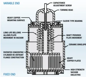
Figure 1 illustrates the construction of a typical Jennings variable vacuum capacitor. Two sets of concentric cylinder plates, one adjustable and the other fixed, are enclosed in an evacuated ceramic envelope with OFHC copper seals at both ends. A flexible metal bellows, attached to a sleeve-type bearing, maintains vacuum while allowing capacitance to vary.
The linear sliding motion required to vary capacitance is converted to rotary tuning via an adjustment screw; in many capacitors, direct pull tuning is an alternative.
Internal breakdown voltage is primarily determined by the spacing of the opposing plates and a high vacuum level.
The following are general specifications pertaining to Jennings vacuum capacitors. Current ratings are for normal convection cooling in ambient temperature of 25°C unless otherwise specified.
Maximum Allowable
Operating Temperature ...125°C (257°F) for ceramic capacitor
Cooling ...Natural convection unless otherwise specified Temperature Coefficient ...Exceeds requirements of MIL-C-23183
Mounting Position ...Any
Rotation to Increase Capacity ...Counterclockwise
Shock ...Exceeds requirements of MIL-C-23183 Vibration ...Exceeds requirements of MIL-C-23183
In these pages, it is possible only to summarize design parameters. More detailed information relating to your specific application can be obtained by contacting us at:
Sales/Marketing Department | 408-282-0363 | [email protected] J e n n i n g s Te c h n o l o g y | 9 7 0 M c L a u g h l i n A v e . | S a n J o s e , C A 9 5 1 2 2 VARIABLE END FIXED END HEAVY COPPER MOUNTING SURFACE SHAFT PROVIDES PLATE MOVEMENT CERAMIC ENVELOPE HEAVY COPPER PLATES HIGH STRENGTH VACUUM DIELECTRIC SLEEVE TYPE BEARING TURNING HEAD CAPACITANCE ADJUSTMENT SCREW PATENTED CONCENTRIC CYLINDER RE-ENTRANT FLANGE CONSTRUCTION LONG LIFE BELLOWS ALLOWS PLATE MOVEMENT IN VACUUM
w w w . j e n n i n g s t e c h . c o m | 4 0 8 - 2 9 2 - 4 0 2 5 5 Current/Voltage
Maximum operating current for vacuum capacitors is limited by temperature rise and working voltage. At lower frequencies, a capacitor is a current-limiting device as a result of its capacitive reactance. At some frequencies, the internal generation of heat exceeds the device’s heat-sinking capabilities, and its current-carrying capacity is limited by thermal considerations. A current vs. frequency chart is provided for each capacitor listed.
Peak voltage is limited by mechanical design of the capacitor. It does not vary with frequency.
Temperature
Jennings Technology vacuum capacitors are designed to meet MIL-C-23183 specifications. Our capacitors are rated for a maximum operating temperature of 125°C (257°F) with normal convection cooling at an ambient temperature of 25°C (72°F).
Current
The current rating provided in the tables in this catalog is the maximum current the vacuum capacitor at maximum working voltage can handle continuously under normal convection cooling at an ambient temperature of 25°C.
Pulse Ratings — Continuous RF current ratings may be exceeded for short
periods if the working voltage rating is not exceeded. This applies particularly to pulse and peaks-of-modulation applications. Momentary currents may exceed the catalog continuous current rating by a factor of the square root of the duty cycle, provided the working voltage is not exceeded.
Amplitude Modulation Ratings — Capacitors in AM service must be able
to withstand peaks-of-modulation voltage and current.
Current ratings are based on temperature, so the heating effects of the modulated currents determine the capacitor requirements.
The average output power of an AM transmitter that is 100% sine wave modulated is 1.5 times the unmodulated carrier power. The average modulated carrier current is 1.225 times the unmodulated carrier current. Therefore, a capacitor current rating of 1.2 times the carrier current will be sufficient, even though the peaks-of-modulation currents are twice the carrier current.
High-current applications?
Jennings pV series capacitors set a new standard for vacuum variable capacitors.One of the latest innovations to emerge from Jennings Technology, the PV Series of vacuum variable capacitors was designed to withstand rugged, high-current environments to meet the increasing demands of semiconductor-processing applications.
Jennings quality engineers put the PV Series capacitors through rigorous testing. All tested units achieved more than 2.5 million cycles while still meeting their original specifications, and many exceeded 3.8 million cycles. For detailed test results, contact Jennings at 408-292-4025 or visit www.jenningstech. com/technotes/high_ratings.shtml.
Jennings offers PV Series vacuum variable capacitors in 500, 1000 and 2000pF capacitance. Look for them on pages 23,
Forced Air Cooled and Water Cooled — If higher current ratings are required, capacitors are available with forced-air cooled bellows to operate safely at 200% of the convection-cooled rating. They are identified with a “CAV” model number. Water-cooled capacitors, identified with a model number beginning with “CW,” are also available and are normally limited only by voltage.
On standard convection-cooled capacitors, current rating may be exceeded for short periods of time, providing the rated temperature rise is not exceeded. Under no conditions should the current exceed 150% of convection current rating.
Fixed capacitors can carry more current because they have shorter RF impedance paths. Fixed capacitor current ratings may be increased by forced-air cooling up to voltage and temperature limitations.
Voltage
Two voltage ratings are provided in our product specifications: AC Test Voltage and Working Voltage.
AC Test Voltage is the maximum 60 Hz voltage that can be applied to the capacitor without breakdown
occurring, as indicated by either internal or external arc-over. Capacitors are tested at this voltage as a means of determining the general condition of the capacitor. Customers frequently use such a test in incoming inspection to check for damage in transit. External arc-over is usually an indication of external contamination or high humidity, not a deficient capacitor.
RF Working Voltage is the maximum peak RF voltage that can be applied continuously to the capacitor
without affecting its ability to withstand instantaneous overloads. It has been established as 60% of the Peak Test Voltage rating. The difference between the 60 Hz Test Voltage and the Working Voltage values is the recommended operating safety factor.
For variable capacitors, the voltage rating is essentially constant from maximum capacity to a point near minimum capacity, where it increases significantly. Within the normal accuracy of instrumentation (±3%), voltage ratings should not be exceeded. Jennings RF testing facilities monitor the above characteristics on a 100% basis, and can also do special application testing when required.
DC —Vacuum capacitors should not be operated at DC voltage above the peak RF working voltage.
DC plus RF —For DC plus RF applications, the sum of the DC plus the peak RF voltage should not
exceed the peak RF working voltage.
Capacitors for DC plus RF applications are tested for DC emission on a dielectric strength tester. To meet Jennings Quality Assurance standards, the DC emission current must not exceed ten microamps at the rated working voltage.
Amplitude Modulation —The peak output power of an AM transmitter that is 100% sine wave
modulated is 4.0 times the unmodulated carrier power. The peak RF voltage will be twice that of the unmodulated carrier, and the capacitor should have an RF working voltage rating equal to or greater than this voltage.
w w w . j e n n i n g s t e c h . c o m | 4 0 8 - 2 9 2 - 4 0 2 5 7 Capacitance
Fixed capacitors with a nominal capacitance above 50 pF shall be within ±5%. Capacitors with a nominal capacitance of 50 pF or less shall be within ±10%, or .5 pF, whichever is greater. For variable capacitors, the low end will be equal to or less than minimum rating. The capacitance change is substantially uniform with rotation, and there are no capacitance reversals. Capacitance is within ±10% of the nominal value of the curves shown (Capacity vs. Turns), in the linear portion of this curve.
Automatic Shorting Feature
Some variable capacitors have been designed with an internal shorting device that shorts out the capacitor when it has been turned beyond maximum rated capacitance. This feature is useful for tuning antenna couplers without the vacuum capacitor in the circuit and also serves as a reference point for adjusting the capacitor to a previously measured capacitance value.
Adjustable Capacitors
Jennings Technology capacitors with a model number beginning with a “CAC” or “CAD” designation are adjustable capacitors, designed to be operated as a fixed capacitor, but able to be hand adjusted to any value within their range and then locked in position with a locking nut.
Tracking
Pairs of variable capacitors will track within 10% if set together near the low capacity end of the linear portion of the curve. On special order, units may be obtained to closer tracking tolerances.
Torque/Direct Pull
In variable capacitors, the linear sliding motion of the moving electrode assembly is converted to rotary tuning via a threaded shaft. The torque values given in the tables are the maximum torque needed to reach minimum capacitance when rotated with a standard lead screw; the torque required to tune away from minimum may be less than half this value.
For most variable capacitors, direct pull tuning is an available option to rotary tuning. Maximum required direct pull force values are also given in the tables.
Capacitance range end-stops are built into every variable capacitor. It is recommended that the user install their own external stops to prevent damage from gear-reduction drives.
Quality Factor (Q)
Extremely low losses occur in vacuum capacitors because of the vacuum dielectric, compact construction and use of low-loss ceramic envelopes, as well as copper and precious-metal solder construction. Consequently, vacuum capacitors are able to handle large RF currents at high RF frequencies that would destroy other types of capacitors. The Q factor, or ratio of stored energy to dissipated energy, is typically in the order of 1000 to 5000 and higher.
Equivalent Series Resistance (ESR)
Because Q is a function of frequency, capacity and ESR (Equivalent Series Resistance), it is perhaps more meaningful to consider the value of ESR. In modern high power capacitor applications, ESR is significant for determining cooling requirements. The slight loss results from the RF resistance in the copper. Based on actual tests, the ESR value is not affected by change in capacity, other parameters being fixed. The value of ESR varies over a range of 2 to 20 milliohms from 2 to 30 MHz.
Thermal Stability
Jennings vacuum capacitors are designed to meet MIL-C-23183
specifications, which state that the absolute value of the capacitance change with temperature shall not exceed 1.1% over the applicable operating temperature range. In typical tests, values for ceramic capacitors show a stability within 50 ppm/°C.
Salt Spray and Humidity
Jennings capacitors are designed to withstand the harmful effects of salt spray and humidity without degradation in performance.
Inductance
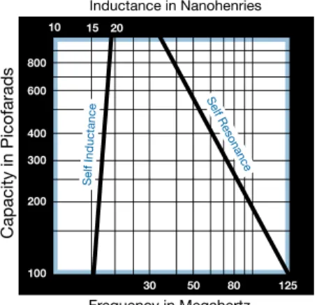
The self-inductance of vacuum variable capacitors is typically in the order of 6 to 20 nanohenries, while that of a fixed capacitor is significantly lower, in the range of 2 to 6 nanohenries.
For most applications, the self-inductance can be ignored. It becomes a factor only when the ratio of capacitive reactance to inductive reactance is small.
Mechanical Life
The mechanical life of variable capacitors is related to length of stroke, speed of operation, bellows material and total number of cycles. Extensive mechanical life tests have been run, operating units for complete cycles from maximum to minimum and back to maximum capacity covering 95% of the full stroke of the movable plates. Capacitors with a large bellows and a short stroke will have the greatest life expectancy under cycling operation. Our most recent variable capacitor models are rated for > 3 million cycles, ideal for the semiconductor processing industry.
Jennings application engineers will be happy to review your specific application to ensure that the optimum capacitor is selected to meet your requirements.
Want more life out of your
capacitors?
Jennings Jenn-x™ vacuum capacitors
last and last!
Representing the next generation of capacitors, Jennings Jenn-X vacuum variable capacitors offer a proven field-service life of approximately 5 million cycles — making them ideal for use in RF tuning circuits for semiconductor processing and other demanding applications, such as induction and dielectric heating, medical imaging and communications. At a cost differential of only about 10% more than standard capacitors of the same type and capacity, the Jenn-X line offers you significant savings in terms of both the labor and materials involved in capacitor replacement.
You can use Jennings Jenn-X capacitors with confidence, knowing Jennings backs their quality and workmanship with an industry-first limited lifetime warranty that ensures prompt repair or replacement of any defective unit within the unit’s lifetime.
Indicated by a model number that begins with “M/,” Jennings Jenn-X vacuum variable capacitors are available in 500pF and 1000pF maximum capacitance. Look for them on
pages 22–23 and 29 of this catalog.
Capacity in Picofarads Inductance in Nanohenries Frequency in Megahertz 800 600 400 300 200 100 10 15 20 30 50 80 125 Self Resonance Self Inductance
Figure 2 — Self-Resonance and Self-Inductance vs. Capacity (Typical Data)
w w w . j e n n i n g s t e c h . c o m | 4 0 8 - 2 9 2 - 4 0 2 5 9 Capacitors in Parallel
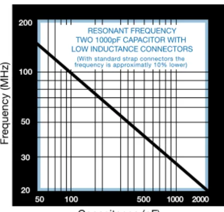
When two or more capacitors are connected in parallel, the inductance of the connecting conductors acting with the capacitors form a tuned circuit. In high current circuits, it is possible to parallel two or more vacuum capacitors to increase capacity. Care must be taken, due to the low loss of the vacuum capacitors and the heavy copper straps paralleling the capacitors, to ensure that the frequency of this series high-Q resonant circuit is above the operating frequency. If the frequency of the series resonant circuit is allowed to become equal to the operating frequency, high currents will be generated, resulting in damage to the capacitor.
All vacuum capacitors have inductance within the connections (Figure 3). The resulting tuned circuit of two 1000pF capacitors in parallel can be kept well above 30 MHz. At low capacities of 50 to 100pF, the resonant frequency can be kept well above 100 MHz.
Figure 4 is a graph of resonant frequency vs. capacity of two 1000pF capacitors with low inductance connections. The resonant frequency of the resulting parellel tuned circuit varies from 20 MHz to 135 MHz from a maximum to minimum capacity.
Testing Standards
Factory — All capacitors are tested for dielectric strength on a 100% basis prior to shipment. Upon customer request, certified test reports will be made available.
Dielectric strength is tested using a low current, high potential source at 60 Hz voltage.
Capacitors for applications involving applied DC voltage should be tested on a DC dielectric strength meter for voltage and emission current. Jennings will test capacitors to this measure if specified by the customer.
User — Most users will find the 60 Hz dielectric strength test adequate and relatively inexpensive. Jennings does not recommend DC testing being performed by the user because of safety considerations. If DC testing is performed, care should be taken not to exceed 60% of the peak test voltage rating of the capacitor.
Fr equency (MHz) Capacitance (pF) 200 100 50 30 20 50 100 500 1000 2000 RESONANT FREQUENCY TWO 1000pF CAPACITOR WITH LOW INDUCTANCE CONNECTORS
(With standard strap connectors the frequency is approximatly 10% lower)
Figure 4 — Resonant Frequency vs. Capacity POOR BETTER FLAT STRAP CAPACITOR CAPACITOR BUCKING LOW INDUCTANCE CONNECTOR
PAN OR DISH TYPE
Figure 3 — Vacuum Capacitors with Inductance within the Connections for Better Performance
Testing Procedure
Apply 60 Hz current-limited voltage across the capacitor. One side may be grounded if desired.
Increase voltage gradually. The rate of increase should be from zero to maximum voltage in one minute. Normal test procedure requires that the capacitor be able to withstand the full rated voltage without barnacles (arcing) occurring after the first minute at the test voltage. A barnacle is a self-healing, non-sustained, momentary breakdown. Weak barnacles that instantly heal are disregarded during the first minute. Under no condition should the test voltage be exceeded.
Arc Detectors — In extremely critical circuit applications, some form of arc detection is necessary. An oscilloscope may be connected across the capacitor to show weak electron discharges, waveform distortion, evidence of strong DC emission currents or corona.
Another form of arc detection may be improvised by using a small neon lamp with one terminal connected to the hot side of the capacitor under test and the other terminal of the lamp floating. The lamp will flash when the capacitor arcs. A contact microphone and audio amplifier connected to the base of the standoff insulator supporting the capacitor under test also makes a very sensitive arc detector.
Installation
Testing — Jennings vacuum capacitors are well packaged and shipped in a manner to ensure safe
delivery. However, during shipping they may be subjected to extreme shock, which could damage the capacitor elements without damaging the shipping container. Therefore, capacitors should be tested upon receipt and before installation. (See Capacitor Testing Procedure above.)
HiPot Testing of Vacuum Capacitors — The most important test for vacuum capacitors is the high
voltage AC HiPot test. It is the indicator of the standoff capability of a capacitor. If the vacuum level of a capacitor decays or there is misalignment of the plates, the standoff capability of the capacitor will be reduced. This test is performed by applying a 50 or 60 Hz AC voltage up to the specified Test Voltage (ETest) of the capacitor. The lower the frequency of a HiPot test, the more stringent it is. Therefore, 50 or 60 Hz is used, even for capacitors to be used in RF applications. Capacitors to be used in DC applications should not be subjected to a DC voltage above the specified Operating Voltage, which is ≤ 60% of the Test Voltage.
Personnel: Trained and qualified to work safely with high voltages.
Equipment: HiPot tester that is certified to meet appropriate government safety standards or an
approved variable AC power supply capable of supplying the voltage required with a current-limiting resistor (R ≥ ETest/Imax) in series between the power supply and the capacitor.
w w w . j e n n i n g s t e c h . c o m | 4 0 8 - 2 9 2 - 4 0 2 5 11 Procedure:
1. Apply ~ 1 kV @ 50 or 60 Hz to the electrodes. Increase the voltage at a rate of 20 kV per minute up to ETest unless there is internal arcing (barnacling) or current flow greater than the charging current of the capacitor that persists for > 2 seconds. In that case, reduce the voltage until barnacling terminates, observe voltage and repeat the process. Continue this process as long as the voltage where arcing is encountered continues to increase up to ETest.
2. If there is any external arcing at any voltage, clean the external surfaces. If conditions are extremely humid, delay testing until it can be done in a lower humidity.
3. Upon experiencing any barnacling or current flow greater than the charging current of the capacitor that persists for > 2 seconds, reduce voltage until barnacling terminates, observe voltage and repeat the process. Continue this process as long as the voltage where arcing is encountered continues to increase up to ETest and is held there for one minute without barnacling or exhibiting current flow greater than the charging current of the capacitor.
4. If there is no persistent barnacling or current flow greater than the charging current of the capacitor (up to ETest), the capacitor has passed the HiPot test. If barnacling is encountered, it is not necessarily a bad capacitor, but it may require reconditioning.
Warning — During installation, avoid twisting or bending strains that could
cause failure of the ceramic-to-metal seal.
Mounting Position — Units may be mounted in any position. When large
capacitors are mounted horizontally, both ends should be supported by standoff insulators to eliminate excessive stresses and possible damage. (Vertical mounting preferred.)
Cooling — Current ratings are determined on the basis of convection cooling
only. It is good design practice to provide an added safety factor by having the variable end mounted on the chassis for heat sinking and by using flexible copper straps for the fixed electrode end. When a large capacitor is being operated near its maximum current rating at high frequencies, there must be adequate space around the unit for convection cooling.
Procedure:
1. Apply ~ 1 kV @ 50 or 60 Hz to the electrodes. Gradually increase the voltage up to ETest unless there is internal arcing (barnacling) or current flow greater than the charging current of the capacitor that persists for > 2 seconds. In that case, reduce the voltage until barnacling terminates, observe voltage and repeat the process. Continue this process as long as the voltage where arcing is encountered continues to increase up to ETest.
2. If there is any external arcing at any voltage, clean the external surfaces. If conditions are extremely humid, delay testing until it can be done in a lower humidity.
3. Upon experiencing any barnacling or current flow greater than the charging current of the capacitor that persists for > 2 seconds, reduce voltage until barnacling terminates, observe voltage and repeat the process. Continue this process as long as the voltage where arcing is encountered continues to increase up to ETest. The capacitor should be held at ETest for one minute without current flow or barnacling. Leave ETest applied for 15 to 20 minutes to complete this session of conditioning.
4. If barnacling is encountered at the same voltage or lower for three successive attempts, discontinue reconditioning. If the capacitor is in warranty, call Jennings Technology’s QA Department at (408) 282-0335 and request an RMA number. Then return it to the factory for evaluation. If it is out of warranty, dispose of it in a safe manner.
5. If conditioning as described in paragraphs 3 and 4 was required, but it passes the one-minute test without current flow or barnacling, allow it to rest for at least 24 hours and repeat the conditioning process for up to three sessions. If it passes the one-minute test described in paragraph 3 after a 24-hour hold, it is adequately conditioned and may be placed into service. If after three sessions, the capacitor continues to barnacle, the capacitor is probably bad.
Vacuum Capacitor Reconditioning
A vacuum capacitor that has exhibited barnacling during incoming inspection, when it has been in storage, or has been used for light duty (low voltage) for a prolonged period may exhibit internal arcing (barnacling) when high voltage is first applied. If this occurs ≤ ETest, it may be an indication that the capacitor needs reconditioning or that it no longer has adequate voltage standoff capability. In this situation, we recommend the following course of action.
Personnel: Trained and qualified to work safely with high
voltages.
Equipment: HiPot tester that is certified to meet appropriate government safety standards or an approved AC variable power supply capable of supplying the voltage required with a current-limiting resistor (R ≥ ETest/Imax) in series between the power supply and the capacitor.
w w w . j e n n i n g s t e c h . c o m | 4 0 8 - 2 9 2 - 4 0 2 5 13
Thermal Expansion — To allow for thermal expansion, at
least one end of the vacuum capacitor should have a flexible connection. In variable capacitors, the flexible connection is normally made to the fixed electrode end. Avoid heavy rigid straps or connections that produce a mechanical strain. The connections should be of substantial area to keep losses low and provide cooling by conduction from both ends. Only a small degree of flexibility is required.
Electrical Connections — Both ends of the capacitor may
be “hot,” or one end may be grounded. Because of the high voltages present, there must be sufficient clearance between the vacuum capacitor and other components to prevent high voltage breakdown. Although the capacitors are designed to ensure optimum electrical field distribution, mounting should be such that adjacent components do not upset this normal electrical field and thus result in excessive heating.
Magnetic Influences — Strong magnetic influences can induce
heating and affect performance of capacitors. Electromagnets have greater effect than permanent magnets.
Transients and Parasitics — Where the possibility exists of
external arcs from transients or parasitic voltages, the capacitor should be protected by adequate corona, or arc shields. Ball gaps are recommended when protection from simple voltage arc cover is required.
Lead Lengths — At high frequencies, avoid long lead length,
because the reactance of the strap will subtract from the reactance of the capacitor and effectively increase the total capacitance. In some cases, the total reactance may be reduced to the point where the minimum capacity of the capacitor will appear too high.
Side Loading — Side loading (radical force applied to lead
screw) will greatly accelerate wear and significantly reduce life. A flexible coupler connection to the lead screw is highly recommended. Increased frequency of 100% minimum to maximum cycling will also be helpful. (See Maintenance.)
Other Precautions — Capacitors should not be used as standoff
insulators to support heavy assemblies.
Only the part of the capacitor specified as the mounting area should be used for that purpose, and any clamps or straps must be attached carefully to avoid stress on the unit, possibly causing seal failure.
Solder connections should not be made directly to the body of the capacitor, nor should there be any contact with the ceramic insulator during operation.
Maintenance
Capacitors operated at normal temperature in a clean environment require no maintenance except to keep them free of dirt accumulation and moisture that may cause a drop in external insulation resistance. A special glaze is applied to all Jennings ceramic capacitors to avoid absorption of moisture and foreign matter.
For variable capacitor applications involving frequent adjustment over a limited range, such as semiconductor impedance matching, it is advisable to cycle completely between minimum and maximum at least 2 cycles every 10,000 cycles to redistribute lubricant.
If variable capacitors are being operated at high temperatures, it is advisable to periodically lubricate the shaft and bearing with a good grade of high temperature light oil and the lead screw with a high temperature, extreme pressure grease.
WARNING
DISCONNECT POWER BEFORESERVICING. HAZARDOUS VOLTAGE CAN SHOCK, BURN
25–30pF
Vacuum
VARIABLE
Capacitors
CADC
-30
CVHD
-25
CADD
-30
15 10 5 Tur ns Curr ent (Amps RMS) Capacity vs Turns Typical Data 5 10 15 20 25 30Continuous RMS Amperes vs Frequency
Frequency (MHz) Capacitance (pF) Min. C 3 pF 30 20 15 10 6 5 4 3 2 2 3 4 5 6 10 15 20 30 40 (at 9kV Peak Working Voltage)
Max. allowable curr ent
30 pF
Mounting: Use Jennings No. 112304 fuse clip, or soldered-on flange-types:
CADC30-XXD1834 (flanges on both ends); CADC30-XXD1823 (fixed end flange only).
.75 .250 .50 1.07 4.12 (104.65 3.05).12 2.68 .06 .5 MAX 1.010 1.31 (33.27) + + + 15 10 5 Tur ns Curr ent (Amps RMS) Capacity vs Turns Typical Data 5 10 15 20 25 30
Continuous RMS Amperes vs Frequency
Frequency (MHz) Capacitance (pF) Min. C 3 pF 30 20 15 10 6 5 4 3 2 2 3 4 5 6 10 15 20 30 40 (at 10.5kV Peak Working Voltage)
Max. allowable curr ent
30 pF
Mounting: Fixed end has threaded hole 6-32 UNC-2B. Maximum screw length 0.17. Variable end threaded or use Jennings No. 111515 fuse clip.
.75 .25 .59 .50 MAX. .31 .78 2.54 .06 1.23 BOTH ENDS 9/16-32UN-2A .250 .50 MIN. REF. (104.64 3.175)4.12 .12 .1.31 (33.27) + + +
Product Number raNge (pF)caPacity test workingVoltage Peak (kV) curreNt amPs. (rms) max.
inches Nom. dimeNsioNs MilliMeters
length diaM. | length diaM. (iN. lbs.) max.torque direct Pull (lbs.) max. Nom. Weight
CVHD–25–45S 6.5–25 45 27 109 6.07 3.65 154 93 2.5 85 5 lb. CVHD–25–50S 6.5–25 50 30 117 6.07 3.65 154 93 2.5 85 5 lb. CVHD–25–55S 6.5–25 55 33 125 6.07 3.65 154 93 2.5 85 5 lb. CADC–30–7.5S 3–30 7.5 4.5 15 4.62 1.30 117.34 33.27 1.5 20 5 oz. CADC–30–10S 3–30 10 6.0 16 4.62 1.30 117.34 33.27 1.5 20 5 oz. CADC–30–15S 3–30 15 9.0 17 4.62 1.30 117.34 33.27 1.5 20 5 oz. CADD–30–0107 3–30 7.5 4.5 18 4.12 1.30 104.65 33.27 1.3 20 6.2 oz. CADD–30–0110 3–30 10 6.0 20 4.12 1.30 104.65 33.27 1.3 20 6.2 oz. CADD–30–0115 3–30 17.5 10.5 30 4.12 1.30 104.65 33.27 1.3 20 6.2 oz.
Mounting: Both ends have tapped holes.
.330 (8.38) Ø 1.35 (34.3) 1.20 (30.5) 0.250/0.248 4.87 (123.7) 3.00 (76.2) INSULATOR SILICONE RUBBER CORONA RING, 2X 3.65 (92.6) MAX Ø 3.40 (86.2) Ø 3.000 (76.2) 1.38 (34.9) .3 MAX (7) 12 10 8 6 4 2 Tur ns Curr ent (Amps RMS) Capacity vs Turns Typical Data 5 10 15 20 25 30
Continuous RMS Amperes vs Frequency
Frequency (MHz) Capacitance (pF) 300 200 100 60 50 20 10 2 1 3 4 5 6 10 20 30 (at 3kV Peak Working Voltage)
25 pF
5 pF
10.5 HARD STOP Rating with water cooling adapter at both ends
Maximum Temperature 125°C. (Actual performance may vary and is dependent
upon the efficiency of the cooling system) Current Limited by
Internal Losses. Conservative Rating
in Dead Air Space. Max. Temp. 125°C.
6X M5 Thread on 2.350 B.C.; 6X M4 Thread on 2.350 B.C.; Both Ends.
15
w w w . j e n n i n g s t e c h . c o m | 4 0 8 - 2 9 2 - 4 0 2 5
Vacuum
VARIABLE
Capacitors
30–60pF
Vacuum
VARIABLE
Capacitors
30–60pF
CVDD
-60
CVDD
-30
3.70 (94.0 1.5).06 3.06 MAX. (77.7) + + 0.50 (12.7) M5X.8 4 HOLES EQ. SP. ON 1.811 BC. BOTH ENDS 0.5 MIN (13) 5.91 (150 .12 3) 2.13 (54.1) + + 1.29 (32.8) 0.250 (6.35) 20 10 5 Tur ns Curr ent (Amps RMS) Capacity vs Turns Typical Data 10 20 30 40 50 60Continuous RMS Amepres vs Frequency
Frequency (MHz) Capacitance (pF) Min. C 9 pF 100 40 50 60 30 20 10 6 5 4 3 2 2 3 4 5 6 10 15 20 30 40 (at 9kV Peak Working Voltage)
Mounting: Both ends have tapped holes.
Max. allowable current
60 pF 15 0.59 (15.00) 1.7 (43) 2.0 (51) 1.23 (31.2) 1.31 0.50 MIN. (12.7) 0.156 DIA 2 HOLES EQ. SP. ON 1.750 BC. BOTH ENDS 0.250 (6.35) (109 3) (33.3) 4.31 .12 2.12 (56.1) + + 15 10 5 Tur ns Curr ent (Amps RMS) Capacity vs Turns Typical Data 5 10 15 20 25 30
Continuous RMS Amperes vs Frequency
Frequency (MHz) Capacitance (pF) Min. C 3 pF 40 30 20 15 10 6 5 4 3 2 2 3 4 5 6 10 15 20 30 40 (at 9kV Peak Working Voltage)
Mounting: Flanges both ends.
Max. allowable curr ent
30 pF Product Number raNge (pF)caPacity test workingVoltage Peak (kV) curreNt amPs. (rms) max.
inches Nom. dimeNsioNs MilliMeters
length diaM. | length diaM. (iN. lbs.) max.torque direct Pull (lbs.) max. Nom. Weight
CVDD–30–0007 3–30 7.5 4.5 18 4.31 2.12 109.47 56.10 1.3 25 6.2 oz. CVDD–30–0010 3–30 10 6.0 19 4.31 2.12 109.47 56.10 1.3 25 6.2 oz. CVDD–30–0015 3–30 15 9.0 30 4.31 2.12 109.47 56.10 1.3 25 6.2 oz. CVDD–60–0010 9–60 10 6.0 50 5.91 3.06 150.00 78.00 3.5 45 2 lb. CVDD–60–0015 9–60 15 9.0 55 5.91 3.06 150.00 78.00 3.5 45 2 lb.
100–125pF
Vacuum
VARIABLE
Capacitors
CVDD
-100
CACAN
-125
C/GCS
-100
.25 (6.35) .81 (21) 1.77 (45) 1.18 (30) REF. .54 (13.7) REF. 1.20 (30.5) REF. .062 (1.6) 3 HOLES .144(3.66) EQ. SP. ON 1.84(46.7) BC. 2.12 (54) 4.76 .20+ (120 .6)+ .2 .32(8) MAX. .44 (11.2) 1.69 (43) 20 10 5 Tur ns Curr ent (Amps RMS) Capacity vs Turns Typical Data 25 50 75 100 125 150Continuous RMS Amperes vs Frequency
Frequency (MHz) Capacitance (pF) Min. C 5 pF 100 40 50 60 30 20 10 6 5 4 3 2 2 3 4 5 6 10 15 20 30 40 (at 9kV Peak Working Voltage)
Mounting: Both ends have tapped holes.
Max. allowable current
100 pF
Product Number raNge (pF)caPacity test workingVoltage Peak (kV) curreNt amPs. (rms) max. inches length diaM. Nom. dimeNsioNs | length diaM. MilliMeters (iN. lbs.) max.torque direct Pull (lbs.) max. Nom. Weight
CVDD–100–7.5S 10–100 7.5 4.5 60 6.62 2.44 168.15 62.00 1.3 30 1 lb. 10 oz. CVDD–100–10S 10–100 10 6.0 65 6.62 2.44 168.15 62.00 1.3 30 1 lb. 10 oz. CVDD–100–15S 10–100 15 9.0 77 6.62 2.44 168.15 62.00 1.3 30 1 lb. 10 oz. C/GCS–100–7.5S 5–100 7.5 4.5 35 4.76 2.12 120.65 53.85 1.9 — .75 lb. C/GCS–100–10S 5–100 10 6.0 40 4.76 2.12 120.65 53.85 1.9 — .75 lb. C/GCS–100–15S 5–100 15 9.0 60 4.76 2.12 120.65 53.85 1.9 — .75 lb. CACAN–125–0003 5–125 3.0 1.8 20 4.65 1.31 118.10 33.27 1.3 20 6.5 oz. CACAN–125–0005 5–125 5.0 3.0 22 4.65 1.31 118.10 33.27 1.25 20 6.5 oz. 6-32 UNC-2B 6 THDS. MIN. 6 HOLES EQ. SP. ON 1.580 B.C. 2.44 MAX. (61.98 MAX.) 1.50 .50 4.81 .06 (168.15 3.05)6.62 .75 1.82 1.29 .375 .12 + + + 15 10 5 Tur ns Curr ent (Amps RMS) Capacity vs Turns Typical Data 20 0 40 60 80 100
Continuous RMS Amperes vs Frequency
Frequency (MHz) Capacitance (pF) Min. C 10 pF 150 100 50 25 15 2 3 4 5 6 10 15 20 30 40 (at 9kV Peak Working Voltage)
Mounting: Fixed end ferrule use FM1H flange. Variable end tapped holes.
Max. allowable curr ent
100 pF
Mounting: Soldered-on flanges.
.25 .59 .03 BOTH ENDS BOTH ENDS .50 MAX. .156 DIA. 2 HOLES EQ. SP. ON1.750 BC. BOTH ENDS .78 .38 2.12 1.31 (33.27) .77 REF. (105.41 3.05) 4.15 2.60 .06 + + .12 + 19 17 15 10 5 0 Tur ns Capacity vs Turns Typical Data 20 40 60 80 100 120 Capacitance (pF) Min. C 5 pF Curr ent (Amps RMS)
Continuous RMS Amperes vs Frequency
Frequency (MHz) 30 20 15 10 6 5 4 3 2 2 3 4 5 6 10 15 20 30 40 (at 3kV Peak Working Voltage)
Max. allowable curr ent
17
w w w . j e n n i n g s t e c h . c o m | 4 0 8 - 2 9 2 - 4 0 2 5
Vacuum
VARIABLE
Capacitors
150–250pF
Vacuum
VARIABLE
Capacitors
150–250pF
CACAN
-250
CVCD
-250
CVDDN
-150
Product Number raNge (pF)caPacity test workingVoltage Peak (kV) curreNt amPs. (rms) max. inches length diaM. Nom. dimeNsioNs | length diaM. MilliMeters (iN. lbs.) max.torque direct Pull (lbs.) max. Nom. Weight
CVDDN–150–0107 10–150 7.5 4.5 50 6.62 2.81 168.10 71.40 1.3 30 1 lb. 10 oz. CVDDN–150–0110 10–150 10 6.0 65 6.62 2.81 168.10 71.40 1.3 30 1 lb. 10 oz. CVDDN–150–0115 10–150 15 9.0 70 6.62 2.81 168.10 71.40 1.3 30 1 lb. 10 oz. CACAN–250–0003 5–250 3.0 1.8 22 4.27 1.31 108.46 33.27 1.5 25 8 oz. CACAN–250–0005 5–250 5.0 3.0 24 4.27 1.31 108.46 33.27 1.5 25 8 oz. CVCD–250–3S 5–250 3.0 1.8 40 6.00 2.44 152.40 61.98 1.5 42 1 lb. 10 oz. CVCD–250–5S 5–250 5.0 3.0 50 6.00 2.44 152.40 61.98 1.5 42 1–lb.–10–oz.
Mounting: Use flange FM1H on fixed end. Tapped holes on variable end.
6-32 NC-2B, 6 THD’S MIN. 6 HOLES EQ. SP. ON 1.580 B.C. 1.820 (46.23) 1.29 (32.8) 0.06 (1.5) 2.81 (71.4) 2.44 MAX. (62.0) 0.375/0.373 (9.53/9.47) 0.75 (19.1) 6.62 .12 0.188 WIDE 6 SLOTS EQ. SP. ON 2.250 BC. (168.1 3.0)+ + + 4.81 .10 (122.2 2.5) + 15 10 5 Tur ns Curr ent (Amps RMS) Capacity vs Turns Typical Data 25 50 75 100 125 150
Continuous RMS Amperes vs Frequency
Frequency (MHz) Capacitance (pF) Min. C 10 pF 100 40 50 60 30 20 10 6 5 4 3 2 2 3 4 5 6 10 15 20 30 40 (at 9kV Peak Working Voltage)
Max. Curr ent 150 pF 24 20 16 8 12 4 Tur ns Curr ent (Amps RMS) Capacity vs Turns Typical Data 50 100 150 200 250 300
Continuous RMS Amperes vs Frequency
Frequency (MHz) Capacitance (pF) Min. C 5 pF 100 40 50 60 30 20 10 6 5 4 3 2 2 3 4 5 6 10 15 20 30 40 (at 3kV Peak Working Voltage)
Mounting: Flange Soldered-on flanges.
Max. allowable curr ent 250 pF 0.250 (6.35) 0.59 (15.0) 0.03 2 PL. (76) BOTH ENDS (58.3) .50 MAX. (12.7) .156 DIA. 2 HOLES EQ. SP. ON1.750 BC. BOTH ENDS 0.99 (25.2) .38 (9.6) 2.12 0.50 REF. (12.7) (108.5 3)4.27 2.78 .06 .12 + + + (70.6 1.5)+ 1.31 6-32 UNC-2B 6 THDS. MIN. 6 HOLES EQ. SP. ON 1.580 B.C. 2.44 MAX. (61.98 MAX.) .31 MIN. 6.00 .12 1.29 1.820 + (152.4 3.05)+ 4.25 .06 + .375 or .218 .75 .38 1.50 .50 15 20 10 5 Tur ns Curr ent (Amps RMS) Capacity vs Turns Typical Data 100 200 300 400 500
Continuous RMS Amperes vs Frequency
Frequency (MHz) Capacitance (pF) Min. C 5 pF 150 100 50 25 15 15 2 3 4 5 6 10 15 20 30 40 (at 3kV Peak Working Voltage)
Mounting: Fixed end ferrule use FM1H flange. Variable end tapped holes.
Max. allowable curr ent
250pF
Vacuum
VARIABLE
Capacitors
CVFP
-250
CVHP
-250
Product Number raNge (pF)caPacity test workingVoltage Peak (kV) curreNt amPs. (rms) max. inches length diaM. Nom. dimeNsioNs | length diaM. MilliMeters (iN. lbs.) max.torque direct Pull (lbs.) max. Nom. Weight
CVFP–250–30S 15–250 30 18 140 9.60 5.56 243.84 142.80 5.6 156 9 lb. 7 oz. CVFP–250–35S 15–250 35 21 150 9.60 5.56 243.84 142.80 5.6 156 9 lb. 7 oz. CVFP–250–40S 15–250 40 24 160 9.60 5.56 243.84 142.80 5.6 156 9 lb. 7 oz. CVHP–250–45S 10–250 45 27 180 11.90 7.20 302.26 182.9 13 156 17 lb. 15 oz. CVHP–250–50S 10–250 50 30 200 11.90 7.20 302.26 182.9 13 156 17 lb. 15 oz. CVHP–250–55S 10–250 55 33 220 11.90 7.20 302.26 182.9 13 156 17 lb. 15 oz. 1/4-20 UNC-2B 9 THDS. MIN. 6 HOLES EQ. SP. ON 3.500 B.C. BOTH ENDS 4.00 BOTH ENDS 5.62 MAX. (142.75 MAX.) 9.60 .20+ (243.84 5.1)+ 6.80 .50 .78 2.00 MAX. .25 MIN. .25 MIN.
Mounting: Both ends have tapped holes.
30 20 10 0 Tur ns Capacity vs Turns Typical Data 100 200 300 400 500 Capacitance (pF) Min. C 15 pF Curr ent (Amps RMS)
Continuous RMS Amperes vs Frequency
Frequency (MHz) 300 200 150 100 60 50 40 30 20 2 3 4 5 6 10 15 20 30 40 (at 24kV Peak Working Voltage)
Max. allowable curr ent 250 pF Typical Data 60 40 20 50 30 10 Tur ns Curr ent (Amps RMS) Capacity vs Turns 100 0 200
Continuous RMS Amperes vs Frequency
Frequency (MHz) Capacitance (pF) Min. C 10 pF 400 200 100 60 30 15 2 4 8 16 32
(at 33kV Peak Working Voltage)
1/4-20 UNC-2B 7 THDS. MIN. 6 HOLES EQ. SP. ON 5.000 B.C. 7.20 MAX. (182.9 MAX.) 11.90 .20 5.50 .06 BOTH ENDS 3.00 + + (302.26 5.08)+ 8.50 .10+ 0.500/0.498 .78
Mounting: Both ends have tapped holes.
Max. allowable curr ent Current limited by capacitance reactance and 33kV peak volts 250 pF 300 400 500
19
w w w . j e n n i n g s t e c h . c o m | 4 0 8 - 2 9 2 - 4 0 2 5
Vacuum
VARIABLE
Capacitors
300–400pF
Vacuum
VARIABLE
Capacitors
300–400pF
CSV1
-300
CVDD
-400
CVDD
-300
Product Number raNge (pF)caPacity test workingVoltage Peak (kV) curreNt amPs. (rms) max. inches length diaM. Nom. dimeNsioNs | length diaM. MilliMeters (iN. lbs.) max.torque direct Pull (lbs.) max. Nom. Weight
CVDD–300–7.5S 10–300 7.5 4.5 75 7.50 3.44 190.50 87.38 1.8 29 3 lb. CVDD–300–10S 10–300 10 6.0 80 7.50 3.44 190.50 87.38 1.8 29 3 lb. CVDD–300–15S 10–300 15 9.0 85 7.50 3.44 190.50 87.38 1.8 29 3 lb. CSV1–300–0103 8–300 3.0 1.8 30 5.35 2.375 60.33 135.89 2 50 1 lb. 2 oz. CSV1–300–0105 8–300 5.0 3.0 40 5.35 2.375 60.33 135.89 2 50 1 lb. 2 oz. CVDD–400–7.5S 20–400 7.5 4.5 70 7.50 3.44 190.50 87.38 2.625 35 3 lb. 1 oz. CVDD–400–10S 20–400 10 6.0 75 7.50 3.44 190.50 87.38 2.625 35 3 lb. 1 oz. CVDD–400–15S 20–400 15 9.0 80 7.50 3.44 190.50 87.38 2.625 35 3 lb. 1 oz. 8-32 7 THDS. MIN. 6 PL. EQ. SP. ON 2.350 (59.69) B.C. 0.78 (19.81) 5.50 .06 (139.70 1.52) .5 (12.70) 7.50 .12 (190.50 3.18) + + + + 2.65 (67.31) 0.500/0.498 (12.700/12.653) 1.29 (32.77) 1.50 (38.10) 3.44 MAX. (87.38 MAX.) 30 20 10 25 15 5 Tur ns Curr ent (Amps RMS) Capacity vs Turns Typical Data 100 200 300 400 500 600
Continuous RMS Amperes vs Frequency
Frequency (MHz) Capacitance (pF) Min. C 10 pF 600 1000 400 500 300 200 100 60 50 40 20 30 2 3 4 5 6 10 15 20 30 40 (at 9kV Peak Working Voltage)
Mounting: Use flange FM1H on fixed end. Tapped holes on variable end.
Max. Allowable Current 300 pF 0.177 DIA. & 0.105 DIA. 3 PL. EQ. SP. ON 2.062 B.C. 3.73 (94.74 1.52).06 0.062 (1.57) 0.20 MIN. (5.08 MIN.) + + 1.62 (41.15 1.52)++.06 0.31 (7.87) .250/0.248 (6.350/6.299) 1.29 (32.77) 2.31 (58.67) 0.81 (20.57) 2.375 MAX. (60.33 MAX.) 0.44 MAX. (11.18 MAX.) 6 4 2 5 3 1 Tur ns Curr ent (Amps RMS) Capacity vs Turns Typical Data 50 100 150 200 250 300
Continuous RMS Amperes vs Frequency
Frequency (MHz) Capacitance (pF) Min. C 8 pF 100 40 50 60 30 20 10 6 5 4 3 2 2 3 4 5 6 10 15 20 30 40 (at 3.0 Peak Working Voltage)
Mounting: Fixed end has tapped holes. Variable end has soldered-on flanges.
allowable curr ent 300 pF 30 20 10 25 15 5 Tur ns Curr ent (Amps RMS) Capacity vs Turns Typical Data 100 200 300 400 500 600
Continuous RMS Amperes vs Frequency
Frequency (MHz) Capacitance (pF) Min. C 20 pF 600 1000 400 500 300 200 100 60 50 40 20 30 2 3 4 5 6 10 15 20 30 40 (at 9kV Peak Working Voltage)
Mounting: Use flange FM1H on fixed end. Tapped holes on variable end.
Max. Allowable Curr ent 400 pF 8-32 7 THDS. MIN. 6 PL. EQ. SP. ON 2.350 (59.7) B.C. 0.78 (19.81) 5.50 .06 (139.70 1.52) 0.31 MIN. (7.87 MIN.) 7.5 .12 (190.50 3.17) + + + + 2.650 (67.31) 0.500/0.498 (12.700/12.653) 1.29 (32.77) 1.50 (38.10) 3.44 MAX. (87.38 MAX.)
450pF
Vacuum
VARIABLE
Capacitors
CVFP
-450
CVHP
-450
Product Number raNge (pF)caPacity test workingVoltage Peak (kV) curreNt amPs. (rms) max. inches length diaM. Nom. dimeNsioNs | length diaM. MilliMeters (iN. lbs.) max.torque direct Pull (lbs.) max. Nom. Weight
CVFP–450–30S 25–450 30 18 150 9.60 5.62 243.8 142.75 5.062 94 9 lb. 7 oz. CVFP–450–35S 25–450 35 21 160 9.60 5.62 243.8 142.75 5.062 94 9 lb. 7 oz. CVFP–450–40S 25–450 40 24 170 9.60 5.62 243.8 142.75 5.062 94 9 lb. 7 oz. CVHP–450–45S 25–450 45 27 200 11.90 7.20 302.3 182.9 8.4 134 18 lb. 8 oz. CVHP–450–50S 25–450 50 30 210 11.90 7.20 302.3 182.9 8.4 134 18 lb. 8 oz. CVHP–450–55S 25–450 55 33 240 11.90 7.20 302.3 182.9 8.4 134 18 lb. 8 oz. 1/4-20 UNC-2B 9 THDS. MIN. 6 HOLES EQ. SP. ON 3.500 B.C. BOTH ENDS 5.62 MAX. (142.75 MAX.) 9.60 .20 4.000 BOTH ENDS + (243.8 5.1)+ 6.80 .10+ 0.500/0.498 .78 2.00 30 20 10 0 Tur ns Curr ent (Amps RMS) Capacity vs Turns Typical Data 100 200 300 400 500
Continuous RMS Amperes vs Frequency
Frequency (MHz) Capacitance (pF) Min. C 25 pF 300 200 150 100 60 50 40 30 20 2 3 4 5 6 10 15 20 30 40 (at 24kV Peak Working Voltage)
Mounting: Both ends have tapped holes.
Max. allowable curr ent 450 pF 1/4-20 UNC-2B 9 THDS. MIN. 6 HOLES EQ. SP. ON 5.000 B.C. 7.2 MAX. (182.9 MAX.) 11.9 .2 5.500 BOTH ENDS 3.00 + (302.3 5.1)+ 8.5 .10+ 0.500/0.498 .78 60 40 20 50 30 10 0 Tur ns Curr ent (Amps RMS) Capacity vs Turns Typical Data 100 200 300 400 500
Continuous RMS Amperes vs Frequency
Frequency (MHz) Capacitance (pF) Min. C 25 pF 400 200 100 60 30 15 2 4 8 16 32
(at 33kV Peak Working Voltage)
Mounting: Both ends have tapped holes.
450 pF
21
w w w . j e n n i n g s t e c h . c o m | 4 0 8 - 2 9 2 - 4 0 2 5
Vacuum
VARIABLE
Capacitors
500pF
Vacuum
VARIABLE
Capacitors
500pF
CSVS
-500
CVDD
-500
CSV1
-500
Product Number raNge (pF)caPacity test workingVoltage Peak (kV) curreNt amPs. (rms) max. inches length diaM. Nom. dimeNsioNs | length diaM. MilliMeters (iN. lbs.) max.torque direct Pull (lbs.) max. Nom. Weight
CSV1–500–0003* 5–500 3.0 1.8 40 5.75 2.375 146.05 60.33 2.0 50 1 lb. 5 oz. CSV1–500–0005* 5–500 5.0 3.0 45 5.75 2.375 146.05 60.33 2.0 50 1 lb. 5 oz. CSVS–500–00031 5–500 3.0 1.8 40 5.75 2.375 146.05 60.33 5 50 1 lb. 8 oz. CSVS–500–00051 5–500 5.0 3.0 45 5.75 2.375 146.05 60.33 5 50 1 lb. 8 oz. CVDD–500–7.5S 20–500 7.5 4.5 80 7.50 3.44 190.50 87.38 1.8 42 3 lb. CVDD–500–10S 20–500 10 6.0 90 7.50 3.44 190.50 87.38 1.8 42 3 lb. CVDD–500–15S 20–500 15 9.0 95 7.50 3.44 190.50 87.38 1.8 42 3 lb. 0.177 DIA. & 6-32 UNC 3 PL. EQ. SP. ON 2.062 B.C. 3.73 (94.74 3.05).12 0.062 (1.575) .41 (10.41) + + 5.75 (146.05 4.83)++.19 0.31 (7.87) .25 (6.35) 1.29 (32.77) 2.31 (58.67) 1.805/1.775 (45.847/45.085) 2.375 MAX. (60.33 MAX.) 0.44 MAX. (11.18 MAX.) 20 5 10 15 0 Tur ns Curr ent (Amps RMS) Capacity vs Turns Typical Data 100 200 300 400 500 600
Continuous RMS Amperes vs Frequency
Frequency (MHz) Capacitance (pF) Min. C 5 pF 150 100 50 25 15 2 3 4 5 6 10 15 20 30 40 (at 3kV Peak Working Voltage)
Mounting: Both ends have tapped holes.
Max. allowable curr ent 500 pF 0.177 DIA. & 0.105 DIA. 3 PL. EQ. SP. ON 2.062 B.C. 3.73 (99.74 1.52).06 0.062 (1.57) .41 (10.41) + + 5.75 .19 (146.05 4.83)++ 0.31 (7.87) .25 (6.35) 1.29 (32.77) 2.31 (58.67) 0.81 (20.57) 2.375 MAX. (60.33 MAX.) 0.44 MAX. (11.18 MAX.) 15 20 10 5 0 Tur ns Curr ent (Amps RMS) Capacity vs Turns Typical Data 100 200 300 400 500
Continuous RMS Amperes vs Frequency
Frequency (MHz) Capacitance (pF) Min. C 5 pF 150 100 50 25 15 2 3 4 5 6 10 15 20 30 40 (at 3kV Peak Working Voltage)
Mounting: Use flange FMOD on fixed end. Variable end has flange soldered on.
Max. allowable curr ent 500 pF
a
a
a
a
a
a
a
a
a
a
8-32 6 THDS. MIN. 6 PL. EQ. SP. ON 2.350 (59.7) B.C. 0.78 (19.81) 5.50 .06 (139.70 1.52) 0.5 MIN. (13 MIN.) 7.5 .12 (190.50 3.05) + + + + 2.65 (67.31) 0.500 (12.7) 1.29 (32.77) 1.50 (38.1) 3.44 MAX. (87.38 MAX.) 30 20 10 25 15 5 Tur ns Curr ent (Amps RMS) Capacity vs Turns Typical Data 100 200 300 400 500 600Continuous RMS Amperes vs Frequency
Frequency (MHz) Capacitance (pF) Min. C 20 pF 600 1000 400 500 300 200 100 60 50 40 20 30 2 3 4 5 6 10 15 20 30 40 (at 9kV Peak Working Voltage)
Mounting: Use flange FM1H on fixed end. Tapped holes on variable end.
Max. Allowable Curr ent
500 pF
Mounting: Both ends have tapped holes. Ø 2.05 (52.1) Ø .98 (24.9) Ø 2.16 (54.8) Ø 2.32 (59) .58 (14.6) 5.18 (131.6) 3.54 (89.9) 1.85 (47) 1.64 (41.7) .070 (1.78) .440 (11.18) 12 10 8 4 6 2 Tur ns Curr ent (Amps RMS) Capacity vs Turns Typical Data 100 200 300 400 500
Continuous RMS Amperes vs Frequency
Frequency (MHz) Capacitance (pF) 300 200 100 60 50 30 20 10 2 1 3 4 5 6 10 20 30 (at 3kV Peak Working Voltage)
Current Limited by Max. Peak RF Voltage. (4.8 kVP) 500 pF 200 pF 100 pF 50 pF
Maximum allowance current at ambient temperature 25 C and surface temperature
125 C with convection cooling. Actual performance may vary and is dependent upon the efficiency of the cooling system. 4x M4 THD on Ø 2.00 B.C. (50.8) M6 THD .31 (8) DP +.00 -.05 Ø .250 (6.35 ) +.000 -.002
500pF
Vacuum
VARIABLE
Capacitors
CVEP
-500
M/CSV5
-500
M/CSVF
-500
Product Number raNge (pF)caPacity test workingVoltage Peak (kV) curreNt amPs. (rms) max. inches length diaM. Nom. dimeNsioNs | length diaM. MilliMeters (iN. lbs.) max.torque direct Pull (lbs.) max. Nom. Weight
CVEP–500–10S 25–500 10 6.0 140 9.40 5.62 238.80 142.75 4.375 61 9 lb. 4 oz. CVEP–500–15S 25–500 15 9.0 150 9.40 5.62 238.80 142.75 4.375 61 9 lb. 4 oz. CVEP–500–20S 25–500 20 12 160 9.40 5.62 238.80 142.75 4.375 61 9 lb. 4 oz. M/CSVF–500–0007* 12–500 7.5 4.5 80 7.88 3.50 200.15 88.90 12 50 3 lb. M/CSVF–500–0010* 12–500 10 6.0 90 7.88 3.50 200.15 88.90 12 50 3 lb. M/CSVF–500–0015* 12–500 15 9.0 100 7.88 3.50 200.15 88.90 12 50 3 lb. M/CSV5–500–05* 50–500 5 3 37 5.18 2.32 132 59 1.9 50 1 lb. 4 oz. M/CSV5–500–08* 50–500 8 4.8 58 5.18 2.32 132 59 1.9 50 1 lb. 4 oz. 15 20 10 5 0 Curr ent (Amps RMS) Capacity vs Turns Typical Data 100 200 300 400 500
Continuous RMS Amperes vs Frequency
Frequency (MHz) Capacitance (pF) Min. C 25 pF 300 200 150 100 60 50 40 30 20 2 3 4 5 6 10 15 20 30 40 (at 12kV Peak Working Voltage)
Mounting: Both ends have tapped holes.
Max. allowable curr ent 500 pF 1/4-20 UNC-2B 9 THDS. MIN. 6 HOLES EQ. SP. ON 3.500 B.C. BOTH ENDS 5.62 MAX. (142.75 MAX.) 9.4 .2 4.000 BOTH ENDS + (238.8 5.1)+ 6.80 .10+ .500/.498 .78 2.00 MAX. *M/C = Long Life Jenn-X
3.73 MIN. .44 MIN. 2.66 MAX. .30 7.53 .12 (191.3 3.0) + + + + 2.02 .01 .44 MAX. 2.03 3.50 MAX. (88.90 MAX.) .250 20 10 25 30 15 5 Tur ns Curr ent (Amps RMS) Capacity vs Turns Typical Data 100 200 300 400 500
Continuous RMS Amperes vs Frequency
Frequency (MHz) Capacitance (pF) Min. C 12 pF 600 1000 400 500 300 200 100 60 50 40 20 30 2 3 4 5 6 10 15 20 30 40 (at 9kV Peak Working Voltage)
Mounting: Use flange FM2S on fixed end. Flange FM2 on variable end.
Max. allowable Curr ent
500 pF
23
w w w . j e n n i n g s t e c h . c o m | 4 0 8 - 2 9 2 - 4 0 2 5
Vacuum
VARIABLE
Capacitors
500pF
Vacuum
VARIABLE
Capacitors
500pF
PV4
-500
M/CSV6
-500
Product Number raNge (pF)caPacity test workingVoltage Peak (kV) curreNt amPs. (rms) max. inches length diaM. Nom. dimeNsioNs | length diaM. MilliMeters (iN. lbs.) max.torque direct Pull (lbs.) max. Nom. Weight
M/CSV6–500–05* 5–500 5 3 47 5.85 2.35 149 60 1.5 50 1 lb. 8 oz. M/CSV6–500–07* 5–500 7 4.2 70 5.85 2.35 149 60 1.5 50 1 lb. 8 oz. PV4–500–15 40–500 15 9 110 5.55 3.4 140.9 86.4 2.062 85 4 lb. 10 oz.
*M/C = Long Life Jenn-X
6X M5 Thread on 2.350 B.C. 6X M4 Thread on 2.350 B.C. Both Ends.
Water cooling disk available: FMWPV, 1 each end. Conservative limit with unit in dead airspace. Maximum temperature 100 °C over ambient.
.85 (21.6) .800 (20.32) 5.55 (140.9) 4.35 (110.5) 1.350 DIA. (34.29) 3.000 DIA. (76.2) 2X 3.25 DIA. (82.6) 3.40 DIA. (86.4) .30 (7.5) 12 10 8 6 4 2 Tur ns Curr ent (Amps RMS) Capacity vs Turns Typical Data 100 200 300 400 500
Continuous RMS Amperes vs Frequency
Frequency (MHz) Capacitance (pF) 300 200 100 60 50 20 10 2 1 3 4 5 6 10 20 30 (at 9kV Peak Working Voltage)
Mounting: Both ends have tapped holes.
500 pF
100 pF Current limited by internal losses. Rating with water cooling at both ends. Maximum
temperature 100 C over ambient
Current Limited by Max. Peak RF Voltage. Ø 0.250/0.248 30 20 10 Capacity vs Turns Typical Data 100 200 300 400 500
Mounting: Both ends have tapped holes, M4.
.06 (1.5) +.000 -.002 +.00 -.05 .10 (2.5) .06 (1.6) .28 (7.1) .06 (1.6) Ø 2.0 (51) Ø 2.4 MAX (59.7) 1.00 (25.4) .41 (10.4) 1.58 (40.1) 3.83 ±.04 (97.3 ±1) 5.85 ±.08 (148.5 ±2) .43 (11) Ø 1.30 (33) .54 (13.8) Ø .250 (6.35 ) Tur ns Curr ent (Amps RMS)
Continuous RMS Amperes vs Frequency
Frequency (MHz) Capacitance (pF) 40 100 20 10 6 5 3 2 1 2 1 3 4 5 6 10 20 30 (at 3kV Peak Working Voltage)
Current Limited by Max. Peak RF Voltage. (4.2 kVP) 500 pF
Current limited by internal losses. Rating at maximum temperature 100 C over
ambient at convection cooling. (Actual performance
may vary and is dependent upon the efficiency of