Reliability Modeling of Direct Current Power Feeding Systems
for Green Data Center
Jung Yul Choi*
Abstract
– Data center is an information hub and resource for information-centric society. Since data center houses hundreds to ten thousands servers, networking and communication equipment, and supporting systems energy saving is one of the hottest issues for green data center. Among several solutions for green data center this paper introduces higher voltage direct current (DC) power feeding system. Contrary to legacy alternating current (AC) power feeding system equipped with Uninterruptible Power Supply (UPS), higher voltage DC power feeding system is reported to be a more energy efficient and reliable solution for green data center thanks to less AC/DC and DC/AC conversions. Main focus of this paper is on reliability issue for reliable and continuous operation of higher voltage DC power feeding system. We present different types of configuration of the power feeding systems according to the level of reliability. We analyze the reliability of the power feeding systems based on M/M/1/N+1/N+1 queueing model. Operation of the power feeding system in case of failure is also presented.Keywords: Direct Current (DC), Failure, Green Data Center, Power Feeding Systems, Reliability
1. Introduction
As Information and Communications Technology (ICT) industry rapidly grows data centers are fast expanding in terms of capacity and sites [1, 2]. Data center is a facility used to house computer servers, switches and routers, storages, and related maintenance systems including cooling and power feeding systems. Since a huge amount of housed systems in data center are operated 24 hours in a day energy efficiency of data center is one of the most important interests in management and economic perspective. There are several solutions for improving energy efficiency of data center such as adoption of new low-power servers, hot spot management and cooling, server and storage virtualization, a new power feeding system, and so on [3]. Among them, this paper considers a higher voltage direct current (DC) power feeding system for a solution to improve the performance of power feeding systems in terms of energy as well as economic perspective toward green data center.
Legacy alternating current (AC) power supply systems, which have been used for a main power supply of data and communications equipment, houses an uninterruptible power supply (UPS) in order to provide power to loads without any interruption against a failure of power supply elements. The core of UPS is a battery system which charges power with direct current (DC) from an AC/DC rectifier. In the operation of battery, a number of AC/DC and DC/AC conversions are inevitably conducted, which is
regarded as a main reason of energy waste in an AC power supply system with UPS. For overcoming the energy inefficiency of an AC power supply, -48V DC power feeding systems have been used in ICT equipment. DC power feeding system enables to remove DC/AC inverter and AC/DC converter in power supply unit in load and provides DC power to the load directly. However, one of serious disadvantages of -48V DC power feeding systems is to require thick diameter power cable due to large load current [4].
Thus, higher voltage DC power feeding systems whose operating voltage range is up to 400V are now discussed1 [4-7]. This higher voltage DC power feeding system has the advantage of -48V DC power feeding system that has less AC/DC conversions while it requires small diameter power cable due to low load current. It gives small form factor and economical. For the success of DC power feeding systems, they should have a certain reliable solution against a failure of power supply elements, such as UPS used for an AC power supply [8-14]. Backup generators and backup batteries for alternative power sources can be considered. Redundant backup components for working components can improve reliability of the power feeding system. This paper presents several configurations of DC power feeding system for high reliability. Different levels of reliability according to the configuration are numerically analyzed based on M/M/1
1 The name of ‘higher voltage’ DC power feeding system is used to
distinguish from -48V DC power feeding system. However, IEC 60364 standard defines Low Voltage as below AC 1000V or DC 1500V. This paper uses interchangeably higher voltage DC power feeding system and DC power feeding system if there is no ambiguity.
† Corresponding Author: Division of Computer Engineering, Sungkyul University, Korea.([email protected])
/N+1/N+1 queueing model. We also present a way to operate the DC power feeding system when a failure occurs.
2. Green Data Center
Data center working as an information hub and resource for information-centered society houses numerous computer servers, storages, and networking systems. For providing secure and reliable data and Internet services, data center operates various supporting systems including cooling and ventilation systems, lighting equipment, power feeding systems, earth/bonding system for safety, energy management system and so on. Since a huge amount of housed systems in data center are operated 24 hours in a day energy efficiency of data center is one of the most important interests in management and economic perspective. In addition, thanks to the explosive increment of various Internet application services and the advent of big data era, the number of data centers as well as the capacity of them is skyrocketing. Energy consumption in data center is consequently far more than ever before.
There are several approaches toward energy efficient data center. One of them is to improve the performance of computer servers in terms of power consumption. Low power and high efficient CPU, cooling devices, power supply systems, and operability in high temperature are such endeavors. Hot spot management is also important for maintaining the proper indoor temperature for stable operation of computer servers. It may be needed to analyze power consumption and usage patterns for optimal management of hot spot. Cooling and ventilation can resolve such hot spots as well as help directly reduce down the indoor temperature. Relocation of equipment by fluid dynamics, inducement of cold air in winter season, avoidance of energy leakage by radiation protection, installation of no windows in certain areas can be helpful [3].
One of the promising solutions for green data center is to apply virtualization technology in computer servers and storages [15]. Even though there are numerous servers and storages in data center, some of them might be low utilized and idle in certain times. We can transfer active processes from low utilized servers to high utilized servers and then turn off idle servers. Such sharing of physical resources and integration of storages into a pool via virtualization enables to reduce down the number of active servers and storages. It can improve the utilization of computer systems as well as downsize the installation space.
Energy efficient power feeding systems, which is the main topic of this paper, is also one of the key technologies in green data center. Not only energy efficient component elements in power feeding systems, but also the way to feed power is the interest. Regarding the way to feed power, higher voltage direct current (DC) for power feeding systems comes into the lime light [4-7, 16].
Besides, green data center needs to have an energy management system that monitors the power consumption and usage patterns of individual systems, sections, floors, and the whole building. Monitoring report can be inputs for server virtualization and storage integration. Energy manager also can diagnose the state of energy consumption of the building and make plans for energy efficient data center.
When we take green data center into consideration, we need to consider how to determine the efficiency of energy of data center. Commonly used metric to determine the energy efficiency of data center is power usage effectiveness (PUE) [17]. PUE is a ratio of the total power entering data center divided by the power used for ICT equipment.
PUE IT E PT F P (1) There are numerous supporting systems for data centers except main ICT systems, such as cooling and ventilation systems, power delivery systems, lighting equipment, and other management systems. Power consumed in such supporting systems should be minimized to improve the energy efficiency of data center. As close as to 1 of PUE is mostly preferable. Practically, however, PUE is more than one and there is a report that the average PUE in data centers in U.S is around 2.0 [18]. This implies that only 50 % of power can be used for ICT equipment and the other power is wasted for the supporting the building. Even though PUE is a good metric that how data centers efficiently uses energy for ICT equipment without wasting energy in supporting equipment, it does not indicate how data center save energy and uses renewable energy. Thus, it is required to develop a new metric to measure the level of greening data center.
3. Direct Current Power Feeding Systems
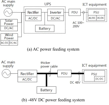
Providing reliable power to ICT equipment is one of the critical missions of green data center. Simple but strong solution for high reliability of data center is to equip alternative backup power sources. Power feeding systems for mission critical buildings such as data center thus equip such backup power sources. One of them is a battery system. Legacy alternating current (AC) power feeding system, which has been used for main power supply of data and communication equipment, contains an Uninterruptible Power Supply (UPS) in order to provide power to loads without any interruption against a failure of power supply elements. The core of UPS is a battery system which charges power with direct current (DC) from AC/DC rectifier. Fig. 1(a) shows a configuration of an AC power feeding system. There are two AC/DC conversions, one DC/AC conversion, and one DC/DC conversion from AC
main power supply to loads (power supply unit, PSU). Inevitable AC/DC and DC/AC conversions are regarded as a main reason of energy waste in AC power feeding system with UPS. If data center is powered by alternative renewable energy such as solar power, wind power, and biofuel, the energy efficiency is dramatically reduced through UPS.
-48V DC power feeding system has been used for telecommunication equipment for better energy efficiency. Since telecommunication equipment is powered by -48V DC from the power feeding system there is no DC/AC inverter and AC/DC conversion in loads as shown in Fig. 1(b). Critical weakness of this power feeding system, however, is to require thick diameter power cable because when it provides the same power to load the current becomes higher due to low voltage. Big power cable takes up much room space in data center and demands higher CAPEX.
In order to overcome the legacy power feeding systems and to build energy efficient data center, a higher voltage DC power feeding system has been discussed [5, 17]. Voltage range discussed is 260 to 400V DC. Merits of the higher voltage power feeding system can be captured from strengths of the two legacy power feeding systems. First, minimizing the AC/DC and DC/AC conversion reduces energy wastes and keeps its energy efficiency especially from renewable energies. It is reported that around up to 15% of energy can be saved compared to AC power feeding system [4]. Second, the reduced number of power conversion elements makes a more reliable power feeding systems compared to AC power feeding system due to less points of failure [19]. Third, power cable size can be smaller because it provides lower current due to higher
voltage for the same power. Consequently, data center can save more space and reduce down CAPEX. This power feeding system can be applied to current ICT equipment without changing power supply module. Depending on the voltage level of DC power feeding systems, however, some ICT equipment may have a new power supply unit (PSU). On the other hand, since the DC power feeding systems uses higher voltage range human safety issue should be settled down for commercial use.
Fig. 2 shows a simple configuration of higher voltage DC power feeding system, which is similar to -48V DC power feeding system. Power from renewable energy is directly provided to power distribution unit (PDU) without AC/DC and DC/AC conversion through a rectifier. Let us consider the DC power feeding system in the aspect of reliability. There may be occurred failures in 1) an AC main power supply, 2) an AC/DC rectifier, and 3) a power distribution unit. Power transmission cable that connects between power supply elements could get cut or failed, but considered rarely happened. In spite of any types of failures, DC power feeding system should provide power to loads (ICT equipment). A representative solution is to equip alternative power sources such as backup generator and battery. Another solution is to equip redundant backup elements of power supply systems.
For example, if an AC main power supply gets failure, a backup generator substitutes the failed AC power supply and provides power to loads. Or, a backup battery can take over the role of power supply. In case of a failure of an AC/DC rectifier or a power distribution unit, there are two possible options: one is to use a backup battery, and the other is to use a substitutive rectifier and power distribution unit if there exist. The following section will describe several configurations of DC power feeding systems for achieving the different levels of reliability.
4. DC Power Feeding Systems Considering
Reliability
4.1 Configuration of DC power feeding systems for higher reliability
This section describes several configurations of DC power feeding systems with different levels of reliability. Fig. 2 shows a simple configuration of a DC power feeding system with backup battery for the role of UPS as legacy AC power feeding systems. Backup battery can provide DC power to loads in case of failure of an AC main supply and an AC/DC rectifier. A backup battery can contain several battery cell strings depending on the volume of power to loads. Parallel configuration of battery cell strings can provide an easy way to replace an aged cell string with a new cell string. This is a minimum configuration for reliability against failures and called a level 1 of reliability. (a) AC power feeding system
(b) -48V DC power feeding system Fig. 1. Legacy power feeding systems
Since there is only one backup power source and limited backup time, its application would be limited to small and less important sites.
Fig. 3(a) equips a backup generator in DC power feeding system with backup battery. Backup generator can substitute an AC main supply in case of its failure. Generator can provide power to loads much longer than battery until fuel runs out. Depending on the duration of backup time and applications in data center, alternative power sources can be selectively applied. Data and telecommunications facility building, such as Internet Data Center (IDCs), which equips a huge amount of ICT equipment, may demand a certain backup system like backup generator. This configuration is called a level 2 of reliability.
Fig. 3(b) shows redundant rectifiers and PDUs in a DC power feeding system with backup generators and batteries. This configuration can protect the rectifying system from a failure of working rectifiers with a backup rectifier. Failed PDUs can be replaced by a backup PDU. These redundant systems can provide continuously power to loads with no help of backup generators and batteries when they get failed simultaneously. Since N working systems share one backup system, it is called N : 1 redundancy. Generally speaking, the higher N produces the lower reliability but the more economical. Depending on the tradeoff of reliability and economics N would be determined. Backup generator and battery also can be configured with redundancy depending on the level of reliability. AC/DC rectifiers can share backup generators. PDU can share backup batteries. There could be several AC main supplies for several AC/DC rectifiers. Since this configuration guarantees better reliability to the DC power feeding systems, it is called a level 3a of reliability.
Fig. 3(c) shows a DC power feeding system configuration with separated power transmission paths from AC main supplies to loads. Power transmission path (PTP) implies a path that power is provided through AC/ DC rectifier and PDU to loads. The path can be consisted of several active paths and a backup path with a backup rectifier and a backup PDU that provides power to loads in case of failures of a rectifiers and a PDU on different paths.
It is much helpful when both a rectifier and a PDU fail simultaneously on a power transmission path. Backup batteries can be shared among power transmission paths or dedicated to a specific path. PSU in ICT equipment may choose one path that can provide power whether the power feeding system fails or not. This configuration is called a level 3b of reliability. Note that reliability level does not guarantee a specific figure of reliability. In addition, depending on the redundancy ratio (N value), it is difficult to judge the superiority among different levels of reliability, Fig. 2. DC power feeding system configuration(level 1 of
reliability)
(a) With backup battery and backup power generator(level 2 of reliability)
(b) Redundant rectifier and PDU with backup generators and batteries(level 3a of reliability)
(c) Power transmission path with redundancy (level 3b of reliability)
Fig. 3. Configuration of DC power feeding systems for reliability
especially for level 3a and level 3b as we will see in Section 4.3. The choice of the level of reliability depends on the importance of loads in data center, and economic and management efficiency.
4.2. Related works
Let us now review the previous studies on reliability in power feeding systems. M. K. Rahmat and et al. proposed to apply Boolean Truth Table to estimate reliability parameters such as MTBF(Mean Time Between Failures) and MTTR(Mean Time To Repair) for the Uninterruptible Power Supply(UPS) [8]. All the possible state combinations for the major components in the UPS are expressed in the Boolean variables, TRUE or FAILURE. This approach is simple and easy to understand the system reliability, but difficult to apply for large systems due to the complexity O(2n). M. K. Rahmat and S. Jovanovic presented a way to estimate the reliability parameters for UPS using the fault tree analysis technique [13]. This approach aims to identify all potential causes leading to system failure. They applied their model to five different UPS topologies. Q. Han presented a reliability model for various configurations of data-telecom power systems [9]. Reliability of the UPS systems is calculated according to the connection type of components in the system: series and parallel. In [10, 11], reliability of UPS was analyzed in order to prove that it can be comparable with DC grade reliability. They claimed that Dual Cord UPS can achieve high reliability having an MTBF in excess of 500 years [11]. T. Tsumura and et al. presented a tool for calculating reliability of power supply based on field data on disturbances and devices failures, which are stored and regularly updated in database [12]. On the other hand, cost-benefit analysis of power feeding system for introducing backup power supply was presented in [14]. Their model based on the discounted cash flow method with the net present value and the interruption frequencies gives a way to consider an optimum power supply configuration.
4.3. Reliability modeling
As a performance metric for reliability of DC power feeding system this paper considers availability. Availability is defined as a probability that a system is available at a specific time. It is also defined as a ratio that a system is available over specific time duration in a steady state. This can be represented by the following equation.
a MTBFMTTRMTBF (2)
MTBF (mean time between failures) is the average life time of a system. MTTR (mean time to repair) is the average amount of time following a failure for a system to be repaired.
Availability calculation of DC power feeding system can be performed by two approaches: series and parallel connections of elements. Let us consider a power transmission path from AC main power supply to load, connected with AC/DC rectifier and PDU in series. The power feeding system is available only if all of the component systems are available. Thus, the availability of DC power feeding system can be calculated by
A ∏ aI
!" (3)
where ai is the availability of system i on the path. I is the number of the components in the path. If system availability is relatively high the availability can be alternatively represented by
A # 1 % ∑ uI ,
!" (4)
where ui is unavailability of element i (=1- ai).
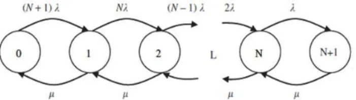
Once system redundancy is applied, availability can be computed by considering parallel connection of systems. There are N working systems with one backup system, which is called N : 1 redundancy. (N is called a redundancy ratio). When one of N working systems gets failed, the backup system can work for the failed system. This type of system connection can be modeled by M/M/1/N+1/N+1 queueing system [20, 21] as shown in Fig. 4. Numbers in each state are the number of failed systems. λ is the mean failure occurrence rate (=1/MTBF) and µ is the mean failure completion rate (=1/MTTR). Based on the queueing system, the availability of system applied with redundancy can be calculated as follows. The probability that k systems are failed is P)*N.)",!*N",! /0µ2 ) P3 (5) where k = 1, 2, …, N+1, and P3 41 5 ∑ *N.)",!*N",! /0µ2 ) N" )!" 6 ." . (6) Since when all systems are available (P0) or only one system is failed (P1), the system is available, the availability of N identical systems with one backup system (a) is obtained by
Fig. 4. M/M/1/N+1/N+1 queueing system for system reliability
a P35 P""∑N;<*N",!/*N.)",!*0/µ,"*N",*0/µ, 9
9=< . (7)
Based on the queueing model, now we can calculate the availability of DC power feeding system with different levels of reliability as shown in Fig. 2 and 3. Since the level 1 and 2 of reliability can be considered as a special case of the level 3a reliability, we can setup the availability model in two types: 1) system redundancy (level 1 to 3a) and 2) power transmission path (PTP) redundancy (level 3b).
Let us first consider the availability of DC power feeding system with system redundancy (level 1 to 3a). We assume that AC main power, AC/DC rectifier, and PDU has N : 1 redundancy so that the availability of these system is calculated by M/M/1/N+1/N+1 queueing model. Backup generator and battery are assumed that there can be one or more systems for that function. Since they are all backup connected in parallel, the availability of the systems can be calculated by 1 % ∏ UN!" , where U is the unavailability of the system. This implies that the system is availability if at least one system is available among the consisting systems for that function. In summary, the power feeding system is available if either AC/DC rectifier or battery is available when PDU is available. Since PDU is the single point of failure, if PDU is unavailable the power feeding system is not available. If battery is not available and rectifier is available, either AC main power or generator should work in order to provide power to loads. The following equation describes the calculation of the system availability.
AS AP?AR*AMAG5 AMUG5 UMAG,UB5
ARAMAG5AMUG5UMAGAB5URAB AP?AR*1 % UMUG,AB5 AR*1 % U MUG,UB5
URABE
AP?AR*1 % UMUG, 5 URABE (8) where AP, AR, and AM are the availability of PDU, AC/DC rectifier, and AC main power, which are all calculated by M/M/1/N+1/N+1 queueing model. AG and AB are the availability of backup power generator and battery, which are calculated by 1 % ∏ UN!" . Table 1 summarizes the availability model for component systems in the power feeding system.
For calculating the availability of level 1 and 2 of reliability from (8), we can set the system availability to be
zero if the system does not exist. If a system does not have a backup system the system availability is set to the given system availability. For example, in case of level 1 of reliability, which has only battery and does not have another redundant backup systems, AS is calculated by aP(aRaM + uRaB), where a implies the given availability without redundancy.
Now let us consider the availability of the power feeding system with power transmission path (PTP) redundancy (level 3b). A single power transmission path consists of AC/DC rectifier, battery, and PDU in series. This availability (APP) is given by
APP AP*ARAB5 ARUB5 URAB,
AP*1 % URUB,. (9)
The availability of power transmission path with redundancy (APTP) can be calculated by M/M/1/N+1/N+1 queueing model. Since the availability computation process using M/M/1/N+1/N+1 queueing model needs λ and µ instead of availability, we uses ρPP (=λ/µ), which is presented by
ρPP".AAPPPP. (10) Consequently, the availability of power feeding system with power transmission path (PTP) redundancy (level 3b) can be calculated as follows.
AS APTP*AMAG5 AMUG5 UMAG,
APTP*1 % UMUG,, (11)
5. Performance Evaluation
Based on the performance modeling for calculating of reliability of different levels of DC power feeding systems, this section presents an exemplified result of performance evaluation. Among the reliability parameters that affect the system reliability, the manufacturer’s given system parameters are critical since they are uncontrollable and fixed values. Reliability parameters are uncertain and variable between similar systems. It must be understood that the intent of this study is to measure how the redundancy policy affect the total reliability of the system but not to obtain accurate value of reliability. Table 2 Table 1. Availability model for individual systems
Systems Availability model
AC main power (AM) M/M/1/N+1/N+1 queueing model
AC/DC rectifier (AR) M/M/1/N+1/N+1 queueing model
PDU (AP) M/M/1/N+1/N+1 queueing model
Generator (AG) 1 % ∏ UN!" G
Battery (AB) 1 % ∏ UN!" B
PTP (APTP) M/M/1/N+1/N+1 queueing model
* U: Unavailability of generator, U: Unavailability of battery
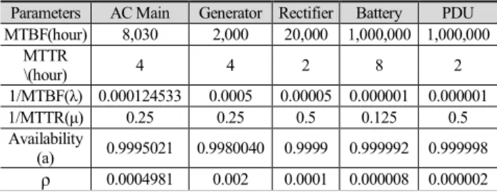
Table 2. Reliability parameters
Parameters AC Main Generator Rectifier Battery PDU MTBF(hour) 8,030 2,000 20,000 1,000,000 1,000,000 MTTR \(hour) 4 4 2 8 2 1/MTBF(λ) 0.000124533 0.0005 0.00005 0.000001 0.000001 1/MTTR(µ) 0.25 0.25 0.5 0.125 0.5 Availability (a) 0.9995021 0.9980040 0.9999 0.999992 0.999998 ρ 0.0004981 0.002 0.0001 0.000008 0.000002
presents reliability parameters that are used in performance evaluation. Values of parameters are referred from the previous study [11].
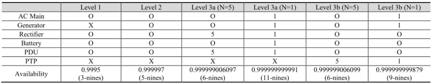
System availability with different redundancy policy is summarized in Table 3. In the table, O implies that there is one working system but no backup system. X implies that the system does not exist in DC power feeding system. 1 or 5 implies the redundancy ratio (N). Level 1 of reliability, which is a basic configuration with battery gives the availability 0.9995. It implies that the power feeding system is not able to provide power to loads during 4.4 hours in a year. Such low availability should be avoided for mission-critical loads in data center. Therefore, efforts to improve reliability of power feeding systems are required. If we add a backup generator on the level 1, the unavailable time decreases up to 1.6 minutes in a year. Even higher
availability can be obtained by apply level 3a or 3b of reliability configuration. Level 3a with 5:1 redundancy produces around six-nines. 1:1 redundancy produces incredibly high availability up to eleven-nines. Difference between Level 3a and 3b is not higher than we expect but the redundancy ratio is the key factor on the reliability. One thing that we should keep in mind is that the increase of reliability comes from the huge amount of investment due to additional redundant backup systems. Therefore, we need to consider both reliability and economics when we design highly reliable DC power feeding system depending on the importance of loads.
6. Operation of DC Power Feeding Systems
in Case of Failures
Based on the proposed configuration of the DC power feeding system, this section shows the operation of the system when a failure occurs. The operation of the power feeding system illustrated in Fig. 5 begins at the failure of an AC main power supply. First, it checks there is an available AC main supply besides the failed supply. If there is, the available AC main supply provides power to an AC/DC rectifier unless the rectifier is out of order simultaneously. If the rectifier also gets failed, we need to check whether there is a backup rectifier or not. If no backup rectifier exists, a backup battery can be applied to provide a complementary power source to loads. This operation is basically performed automatically by the system without manipulating by the operator of the DC power feeding systems because the power supply should be operated without interruption in case of failures.
7. Conclusion
This paper introduced higher voltage DC power feeding systems for energy efficient data center, so-called green data center. To provide secure and reliable power to loads, we presented four configurations depending on the level of reliability. From the performance evaluation based on numerical analysis, the redundancy policy applied to the power feeding system has proved its good effect on highly reliable system. Since higher reliability requires additional Fig. 5. Operation of DC power feeding systems in case of
failure of AC main power supply
Table 3. Availability of DC power feeding systemm with different redundancy polity
Level 1 Level 2 Level 3a (N=5) Level 3a (N=1) Level 3b (N=5) Level 3b (N=1)
AC Main O O O 1 O 1 Generator X O O 1 O 1 Rectifier O O 5 1 O O Battery O O O 1 O O PDU O O 5 1 O O PTP X X X X 5 1
backup systems it should be considered in viewpoint of economical aspect. The meaning of this study can be found that we presented a methodology to measure the reliability level and the configuration of DC power feeding system to achieve the reliability level depending on the importance of loads housed in data center. The following study is expecting to be the analysis of economic aspect of DC power feeding systems for different level of reliability.
Acknowledgements
This paper was supported by Sungkyul University and the ICT Standardization program of KCC (Korea Com-munications Commission).
References
[1] G. Fettweis and E. Zimmermann, ICT Energy Consumption - Trends and Challenges, in Proc. of the 11th International Symposium on Wireless Personal Multimedia Communications (WPMC 2008), 2008. [2] G. Koutitas and P. Demestichas, A Review of Energy
Efficiency in Telecommunication Networks, Telfor Journal, vol. 2, no. 1, 2010.
[3] L.1300, Best Practices for Green Data Centers, ITU-T SG5, Nov. 2011.
[4] T. Babasaki, T. Tanaka, Y. Nozaki, T. Tanaka, T. Aoki, and F. Kurokawa, Developing of Higher Voltage Direct-Current Power-feeding Prototype System, in Proc. of the 31st International Telecommunications Energy Conference (INTELEC 2009), 2009.
[5] L. 1200, Specification of DC Power Feeding System Interface, ITU-T SG5, Apr. 2012.
[6] D. J. Becker and B. J. Sonnenberg, 400Vdc Power Distribution: Overcoming the Challenges, in Proc. of the 32nd International Telecommunications Energy Conference (INTELEC 2010), June 2010.
[7] H. Pang, B. M. H. Pong, and E. W. C. Lo, A practical and efficient DC distribution system for commercial and residential applications – 240V or higher?, in Proc. of the International Conference on Electrical Engineering 2008, No. O-198, July 2008.
[8] M. Rahmat, S. Jovanovic and K. Lo, Reliability Estimation of Uninterruptible Power Supply Systems: Boolean Truth Table Method, in Proc. of 28th Inter-national Telecommunications Energy Conference (INTELEC 2006), Sept. 2006.
[9] Q. Han, Data-telecom Power System Solution Based on Reliability Analysis, in Proc. of 29th International Telecommunications Energy Conference (INTELEC 2007), pp. 917-922, Sept. 2007
[10] F. Bodi, “DC-Grade” Reliability for UPS in Tele-communications Data Centers, in Proc. of 29th International Telecommunications Energy Conference
(INTELEC 2007), pp. 595-602, Sept. 2007
[11] F. Bodi, “DC-Grade” Reliability Part 2 – Ultra Reliable, Green UPS for Telecommunications Data Centers, in Proc. of 30th International Telecommuni-cations Energy Conference (INTELEC 2008), Sept. 2008. [12] T. Tsumura, T. Takeda and K. Hirose, A Tool for
Calculating Reliability of Power Supply for Infor-mation and Communication Technology Systems, in Proc. of 30th International Telecommunications Energy Conference (INTELEC 2008), Sept. 2008.
[13] M. Rahmat and S. Jovanovic, Reliability Modeling of Uninterruptible Power Supply Systems Using Fault Tree Analysis Method, Vol. 19, No. 2, pp. 258-273, European Transactions on Electrical Power, Mar. 2009. [14] K. Hirose, T. Matsumura and M. Yamasaki,
Cost-benefit Analysis of Emergency Backup Power Systems for Mission Critical Applications, in Proc. of the 32nd International Telecommunications Energy Conference (INTELEC 2010), June 2010.
[15] L. Liu, H. Wang, X. Liu, X. Jin, W. He, Q. Wang, and Y. Chen, GreenCloud: a new architecture for green data center, Proc. of the 6th International Conference on Autonomic Computing and Communications, pp. 29-38, June 2009.
[16] J. Choi and S. Qi, Architecture of DC power feeding systems, a working document (TD1185) in ITU-T SG5, Apr. 2012.
[17] Green Grid Consortium, www.thegreengrid.org [18] Report to Congress on Server and Data Center Energy
Efficiency, U.S. Environmental Protection Agency ENERGY STAR Program, 2007.
[19] H. Ikebe, Power Systems for Telecommunications in the IT Age, Proc. of Internation Telecommunications Energy Conference(INTELEC 2003), pp. 1-8, Oct. 2003. [20] Kleinrock L. Queueing systems, vol. 1: theory. Wiley
& Sons; 1975.
[21] J. Choi, S. Woo and B. Shim, Reliable Service Pro-visioning in Converged Multimedia Network Envir-onment, Journal of Network and Computer Applications, Vol. 34, No. 1, pp. 394-401, Jan. 2011.
JungYul Choi He received B.S degree from Inha University in 2000, and M.S degree and Ph.D degree from Korea Advanced Institute of Science and Technology in 2002 and 2006. He worked for the Network R&D Labora-tory, Korea Telecom, from 2006 to 2011. He is an assistant professor in the Division of Computer Engineering, Sungkyul University, Korea, since 2011. His research interests are green data center, green communications networks, cloud computing and future networks.