DISTRIBUTED SHARED MEMORY
SUPPORT in GMAC
Bachelor’s Thesis
Author: Khalid Mahyou Supervisor: Javier CabezasBarcelona Supercomputing center
Co-Supervisor:
Agust´ın Fern´andez
Department of Computer Architecture
Bachelor Degree in Informatics Engineering Computer Engineering Specialization Facultat d’Inform`atica de Barcelona - FIB
Universitat Polit`ecnica de Catalunya (UPC) - BarcelonaTech June 26th, 2014
Heterogeneous computing combines general purpose CPUs with accelerators to efficiently execute both: sequential control-intensive and data parallel phases of applications. Exist-ing programmExist-ing models for heterogeneous computExist-ing rely on programmers to explicitly manage the different memories in the system and manage data transfers between the CPU system memory and accelerator memory.
To facilitate the programming of accelerator-based systems, has created a library called GMAC. This model basically abstracts the developer from the peculiarities of each partic-ular system and proposes a simple API to replace the host code for devices management for a more generic one. Programming with GMAC, the programmer does not need to manage data transfers between different devices. This action is done internally by GMAC. In this project we improve GMAC with new capabilities and also improve already existing functions. First, we have developed a utility that divide the shared data space into similar blocks in length. Secondly, we have developed a memory coherence protocol to maintain all shared data coherent along all the devices. Also, we have checked that all the functions, already implemented, work with this new system. And finally, we performed a set of tests to check that every function in the system work properly.
La computaci´o heterog`enia combina les CPUs de prop`osit general amb acceleradors per executar de manera eficient tant: la part seq¨uencial per al control-intensiu com les fases paral.leles de les dades de les aplicacions. Els Models de programaci´o existents per a la computaci´o heterog`enia depenen dels programadors per gestionar de forma expl´ıcita les diferents mem`ories que hi ha al sistema i gestionar les transfer`encies de dades entre la mem`oria del sistema de la CPU i de la mem`oria de l’accelerador.
Per facilitar la programaci´e de sistemes basades en acceleradors, s’ha creat una llibreria anomenada GMAC. Aquest model b`asicament abstreu el desenvolupador de les peculiari-tats de cada sistema en particular i proposa una API senzilla per reempla¸car el codi del host per a la gesti´o de dispositius per un de m´es gen`eric. Programar amb GMAC, el pro-gramador no t´e cap necessitat per gestionar les transfer`encies de dades entre els diferents dispositius. Aquesta acci´o es porta a terme internament per GMAC.
En aquest projecte millorem GMAC amb noves capacitats i millorar les funcions ja exis-tents. En primer lloc, hem desenvolupat una utilitat que divideix l’espai de dades com-partit en blocs similars en longitud. En segon lloc, hem desenvolupat un protocol de coher`encia de mem`oria per mantenir totes les dades compartides coherents al llarg de tots els dispositius. A m´es, hem comprovat que totes les funcions, ja implementades, funcionen amb aquest nou sistema. I, finalment, es va realitzar una s`erie de proves per comprovar que totes les funcions en el sistema funcionen correctament.
La computaci´on heterog´enea combina las CPUs de prop´osito general con aceleradores para ejecutar de manera eficiente tanto: la parte secuencial para el control-intensivo como las fases paralelas de los datos de las aplicaciones. Los Modelos de programaci´on existentes para la computaci´on heterog´enea dependen de los programadores para gestionar de forma expl´ıcita las diferentes memorias que ha en el sistema i gestionar las transferencias de datos entre la memoria del sistema de la CPU y de la memoria del acelerador.
Para facilitar la programaci´on de sistemas basadas en aceleradores, se ha creado una librer´ıa llamada GMAC. Este modelo b´asicamente abstrae al desarrollador de las peculia-ridades de cada sistema en particular y propone una API sencilla para reemplazar el c´odigo del host para la gesti´on de dispositivos por uno m´as gen´erico. Programar con GMAC, el programador no tiene ninguna necesidad para gestionar las transferencias de datos entre los diferentes dispositivos. Esta acci´on se lleva a cabo internamente por GMAC.
En este proyecto mejoramos GMAC con nuevas capacidades y mejorar las funciones ya existentes. En primer lugar, hemos desarrollado una utilidad que divide el espacio de datos compartido en bloques similares en longitud. En segundo lugar, hemos desarrollado un protocolo de coherencia de memoria para mantener todos los datos compartidos coherentes a lo largo de todos los dispositivos. Adem´as, hemos comprobado que todas las funciones, ya implementadas, funcionan con este nuevo sistema. Y, por ´ultimo, se realiz´o una serie de pruebas para comprobar que todas las funciones en el sistema funcionan correctamente.
This project has benefited greatly from the support of many people, some of whom I would sincerely to thank.
I would like to thank my supervisor Javier Cabezas for his helpful suggestions, his help, corrections and constructive feedback during all the phases of this project. Without his help, this project wouldn’t have finished.
I would also like to thank my co-supervisors Agust´ın Fern´andez and Nacho Navarro for their guidance in this project and discussions on the topic.
In third place, I would like to thank my friends and colleagues at the Barcelona School of Informatics. Thanks to all of you who have always been my side during this experience.
Finally, but first in my heart, I would like to thank my parents. They are due my deep gratitude for their continued moral support and encouragement throughout my studies.
Abstract ii Resum iii Resumen iv Acknowledgements v Table of Contents vi 1 Introduction 1 1.1 Introduction. . . 1 1.2 Project Overview . . . 2 1.3 Goals . . . 2 1.4 Technical Competencies . . . 2 2 Analysis 4 2.1 State of the Art. . . 4
2.1.1 Technology overview . . . 4 2.1.2 Related work . . . 6 2.2 Stakeholders. . . 6 2.3 Risks. . . 7 3 Heterogeneous Computing 8 3.1 Introduction. . . 8 3.1.1 GPU Architecture . . . 10 3.1.2 CPU-GPU Connection . . . 11
3.1.3 Parallel Programming Languages . . . 12
3.2 CUDA . . . 13
3.2.1 Introduction . . . 13
3.2.2 Data Parallelism Model . . . 13
3.2.3 CUDA Program Structure . . . 14
3.2.4 Device Memories and Data Transfer . . . 16
3.2.5 Kernel Functions . . . 19 3.2.6 CUDA Threads . . . 22 3.2.7 CUDA vs. OpenCL . . . 22 4 GMAC 24 4.1 Introduction. . . 24 4.2 Overall Design . . . 25 4.3 Memory Model . . . 25 4.4 Execution Model . . . 26
4.5 GMAC code example. . . 26
5 Design and Implementation 29 5.1 Shared Address Space . . . 29
5.2 Memory Coherence Protocol. . . 32
5.3 Improvements . . . 34 6 Testing 35 6.1 Test Environment. . . 35 6.2 Tests . . . 35 6.2.1 Unit Tests . . . 37 7 Management 40 7.1 Planning. . . 40 7.1.1 Task Description . . . 40 7.1.2 Gantt Diagram . . . 41 7.2 Budget. . . 42 7.2.1 Human Resources . . . 43 7.2.2 Material Resources . . . 44 7.2.3 Total Cost. . . 44 7.2.4 Viability . . . 45 7.3 Methodology . . . 45
7.4 Laws and Regulations . . . 46
7.5 Sustainability and Social Impact . . . 47
7.5.1 Social impact . . . 47 7.5.2 Environment impact . . . 47 7.5.3 Economic impact . . . 48 8 Conclusions 49 9 Future Work 51 Glossary 52 Bibliography 54 A GMAC API 56 A.1 GMAC API . . . 56
A.2 DSM manager interface . . . 60
B Matrix Multiplication 65 B.1 C++ Source Code . . . 65
B.2 CUDA Source Code . . . 67
B.3 GMAC Source Code . . . 71
List of Figures 74
List of Tables 75
Introduction
1.1 Introduction
Traditionally, the use of GPUs (Graphics Processing Units) was limited to computing graphics or image processing. In recent years, nevertheless, has begun to use, such pro-cessors, for computing applications where traditionally general-purpose CPUs (Central Processing Units)are used. Currently, though graphics processors are designed primarily for generation of 3D graphics, fulfil certain characteristics that make them very attractive for computing.
Heterogeneouscomputing combines general purpose CPUs with accelerators to efficiently execute both: sequential control-intensive and data parallel phases of applications. Nowa-days, heterogeneous system architecture utilize multiple processor types usually on the same silicon die, to give the best of both worlds: GPUs processing, apart from its well known 3D graphics rendering capabilities, can also perform mathematically intensive com-putations on very large data sets, whileCPUscan run the operating system and perform traditional serial tasks.
There are various existing programming models for heterogeneous computing. The two most important are: CUDA (Compute Unified Device Architecture), owned by Nvidia and therefore is only executable on NvidiaGPUs; and for the other hand,OpenCL (Open Com-puting Language), which is an open standard and developed by a group called khronos. All of the existing programming models rely on programmers to explicitly manage the different memories in the system and manage data transfers between the CPU system memory and accelerator memory.
To facilitate the programming of theGPUs, it has created a library calledGMAC (Global Memory ACcelerators). GMAC is a user-level library that provides a programming model for that issue. This model basically abstracts the developer from the peculiarities of each particular system and proposes a simple API (Application Programming Interface) to replace the host code for devices management for a more generic one. The programmer does not need to manage any memory or data transfers between different devices. This action is done internally by the library.
In this project our work consists to improveGMACwith new capabilities and also improve already existing functions. First, we have developed a utility that divide the shared data
space into similar blocks. All these blocks has the same length and they are fixed. Secondly, we have developed a memory coherence protocol to maintain all shared data coherent along all the devices address space. Also, we have checked that all the functions, already implemented, work with this new system. And finally, we performed a set of tests to check that every function in the system work properly.
1.2 Project Overview
The project is part of a project to develop a library that serves as a run-time, called GMAC to simplify the programmability of applications in heterogeneous architectures. One of theGMAC goals is to abstract the programmer of the type ofAPI that hardware accelerator uses, trying to simplify the two major programming platforms of acceleratos, CUDAand OpenCL.
The project will consist in the development of the necessary support for memory manage-ment. First off, we will implement the shared address space between the accelerator (GPU) and CPU. And lastly, we will implement the memory coherence protocol. In Chapter 5, we explain most deeply what these terms mean.
1.3 Goals
The main goal of this project is to develop of the necessary support for memory manage-ment. Therefore, the concrete goals for the project are as follows:
• The first objective is a personal goal and consists to acquire new knowledge about heterogeneous systems and how to deal with them.
• Provide GMAC library with new functionalities.
• Improve the library that allow users, engineers, and other stuff to use and program their applications with it.
1.4 Technical Competencies
Bellow follows a commentary on the particular competencies that were listed at the start of the project:
CEC2.1: Analyse, evaluate, select and configure hardware platforms for the devel-opment and execution of computer applications and services. [Competent]
This competence has been used during the first phases of the project, with the anal-ysis of the existing architectures and the whole software they use to work properly. CEC2.2: Program taking into account the hardware architecture, using assembly
All programming has been made, in C++ language, thinking about how GPUsand CPUs can interact and share information with each other. For that reason, we had to know how memory works.
CEC2.3: Develop and analyse software for systems based on microprocessors and its interfaces with users and other devices. [In depth]
All work has been done considering the hardware Accelerators. we have also made tests to evaluate the work done. With this work we improve theGMAClibrary with improvements to make it easy for the programmers or users develop their application. CEC2.4: To design and implement system and communications software.
[Compe-tent]
The core of this project is to develop of the necessary support for information sharing between CPUsand GPUs. Thus, we developed our system to deal with this.
Analysis
In this chapter we will discuss the analysis that has been done of the project.
2.1 State of the Art
In order to start with the project, we must analyse the state of the art. First, we will talk about existing technologies, architectures and products related to out project. And finally, we will talk about previous work done in the field.
2.1.1 Technology overview
Heterogeneouscomputing combines general-purpose CPUswith accelerators to efficiently execute both sequential control intensive and data parallel phases of applications. Exist-ing programmExist-ing models forheterogeneous computing rely on programmers to explicitly manage data transfers between theCPU system memory and accelerator memory. Maximizing multi thread throughput and minimizing single-thread latency are two design goals that impose very different and often conflicting requirements on processor design. For example, the Intel Xeon E7 family [9] processors consist of six processor cores each of which is an high frequency out-of-order, multi instruction issue processor with a sophisticated branch prediction mechanism to achieve short single thread execution latency. This is in contras to the NVIDIA Tesla GT200 GPU [12] design that achieves high multi thread throughput with many cores, each of which is a moderate frequency, multi threaded, in-order processor that shares its control unit and instruction cache with seven other cores. For control intensive code, the Intel Xeon design can easily outperform the NVIDIA Tesla. For massively data parallel applications, the NVIDIA Tesla design can easily achieve higher performance than the Intel Xeon.
Data parallel code has the property that multiple instances of the code can be executed concurrently on different data. Data parallelism exists in many applications such as weather prediction, financial analysis, medical imaging and physics simulation. Most of these applications also have control intensive phases that are often interleaved between data parallel phases. Hence, general-purpose CPUs and accelerators can be combined to formheterogeneous parallel computing systems that efficiently execute all application phases [19].
General-purpose CPUs and accelerators can be coupled in many different ways. Fine-grained accelerators are usually attached as functional units inside the processor pipeline. In the Cell BE chip, the synergistic processing units, L2 cache controller, the memory interface controller, and the bus interface controller are connected through an Element Interconnect Bus [10]. The Intel Graphics Media Accelerator is integrated inside the graphics and memory controller hub that manages the flow of information between the processor, the system memory interface, the graphics interface, and the I/O controller [8]. AMD Fusion chips will integrate CPU, memory controller and GPU into a single chip. A common characteristic among Cell BE, Intel Graphics Media Accelerator, and AMD Fusion is that general-purposeGPUsand accelerators share access to system memory. In these systems, the system memory controller deals with memory requests coming from both general-purposeCPUsand accelerators.
Accelerators and general-purpose CPUs impose very different requirements on the sys-tem memory controller. General-purposeCPUs are designed to minimize the instruction latency and typically implement some form of strong memory consistency. Accelerators are designed to maximize data throughput and implement weak forms of memory consis-tency. Memory controllers for general-purposeCPUs tend to implement narrow memory buses (e.g. 192 bits for the Intel Core i7) compared to data parallel accelerators (e.g. 512 bits for the NVIDIA GTX280) to minimize the memory access time. Relaxed consistency models implemented by accelerators allow memory controllers to serve several requests in a single memory access. Strong consistency models required by general-purposeCPUs do not offer the same freedom to rearrange accesses to system memory. Memory access scheduling in the memory controller has different requirements for general-purposeCPUs and accelerators (i.e., latency vs throughput).
Programming models for current heterogeneous parallel systems, such as CUDA [3] and OpenCL[25], present different memories in the system as distinct memory spaces to the programmer. Applications explicitly request memory from a given memory space and perform data transfers between different memory spaces.
Such programming models ensure that data structures reside in the memory of the proces-sor (CPUor accelerator), that performs subsequent computations. These models also im-ply that programmers must explicitly request memory on different processors and, thus, a data structure is referenced by two different memory addresses, a virtual address in system memory and a physical address in the accelerator memory. Programmers must explicitly manage memory coherence before executing kernels on the accelerator. This approach also prevents parameters from being passed by reference to accelerator kernels [5] and computationally critical methods to return pointers to the output data structures instead of returning the whole output data structure, which would save bandwidth whenever the code at CPU only requires accessing a small portion of the returned data structure. These approaches harm portability because they expose data transfer details of the underlying hardware. Offering a programming interface that requires a single allocation call and re-moves the need for explicit data transfers would increase programmability and portability of heterogeneous systems.
2.1.2 Related work
Most programming models proposed for massively parallel systems deal with data distribu-tion and kernel scheduling on clusters of computers. Global Arrays [15] provide semantics to divide and access arrays on a distributed memory system. In a data-centric program-ming model, the accelerator memory hosts all data required by accelerator kernels and, therefore, no data distribution is required if only one accelerator is used for each kernel ex-ecution. Global Arrays are compatible with a data centric programming model and might be used if the execution of a kernel is distributed among several accelerators. ASSIST [27] decomposes programs into components that communicate through data streams. AS-SIST requires the programmer to declare modules and connect them using streams. This data dependence information is used by the ASSIST run-time to schedule the execution of modules on different processors. A data centric programming model also requires the programmer to assign data structures to computational intensive kernels.
Software development kits for commercially available accelerators such as the Cell Runtime Management Library [7], NVIDIACUDA[17][16] orOpenCL[18], require programmers to explicitly move data between system memory and accelerator memory prior to performing any calculation using these data structures on the accelerator. The libraryGMACremoves the need for explicit data transfers, thus easing application development, and usesCUDA orOpenCLto interact withGPUaccelerators. OmpSs [4][1] is a programming model where programmers identify tasks and their input and output parameters through source code annotations. The OmpSs run-time exploits task-level parallelism by executing independent tasks concurrently. OmpSs differs from the data centric programming model in that OmpSs identifies input and output parameters whose value is only known at the method call time, instead of data structures. Hence, the OmpSs does not allow data to be eagerly transferred to or from accelerators.
2.2 Stakeholders
There are several actors interested in the development of this project. Specifically, we have detected three main actors that directly involved with the project:
• Author
The author of this project is the most important because its aim is to finish the job in time established planning to finish his degree. This will motivate him to invest the necessary time to carry out the objectives.
• Supervisor and co-supervisors
The supervisor and co-supervisors will have a library after the project reaches its end, which can develop a GPU based program more easily, without taking into account either data transfer or sharing data, nor the consistency between all the memories the system.
• Potential customers
We can distinguish two types of prospects: those who want to use our library in their applications and those who want to use it in research groups to develop other methods or other libraries. Customers who could use the library might be physicists, biologists, mathematicians, or any other discipline that are not necessarily computer engineers that must know how to deal with memory management of the various devices involved in the system. Also, might be any type of customer who want to develop applications in CUDA or OpenCL, and still does not want to move data from one place to another and making copies of data.
2.3 Risks
During the development of this project we must take into account the risks involved in the process in order to detect their appearance as soon as possible. Some of the most evident risks are as follows:
• Many different graphics cards. Currently on the market there are a variety of graphics cards and each one is different from another. To support all of them is a bit difficult. Given that almost every 6 months there is a new graphics card on the market.
• Competition. The leading companies in the field (Nvidia, AMD), who are manu-facturing graphics cards, or any other institution can find a quick and easy way to carry out this purpose, even this project has not been finished yet.
• Time. The project will not be ready in time if any deviation occurs or arises any difficulty. To avoid this, we have made regular meetings during the course of the project.
Heterogeneous Computing
3.1 Introduction
Microprocessors based on a singleCPU, such as those in the Intel Pentium family and the AMD Opteron family, drove rapid performance increases and cost reductions in computer applications for more than two decades. These microprocessors brought GFLOPS (Giga FLoating-point Operations Per Second)to the desktop and hundreds ofGFLOPSto cluster servers. This relentless drive of performance improvement has allowed application software to provide more functionality and generate more useful results. The users, in turn, demand even more improvements once they become accustomed to these improvements, creating a positive cycle for the computer industry.
During the drive, most software developers have relied on the advances in hardware to increase the speed of their applications under the hood: the same software simply runs faster as each new generation of processors is introduced. This drive, however, has slowed since few years ago due to energy consumption and heat dissipation issues that have limited the increase of the clock frequency and the level of productive activities that can be performed in each clock period within a singleCPU. Virtually all microprocessor vendors have switched to models where multiple processing units, referred to as processor cores, are used in each chip to increase the processing power.
Traditionally, the vast majority of software applications are written as sequential programs. The execution of these programs can be understood by a human sequentially stepping through the code. A sequential program will only run on one of the processor cores, which will not become significantly faster than those in use today.
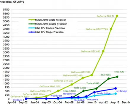
The semiconductor industry has settled on two main trajectories for designing micropro-cessor. The multi-core trajectory seeks to maintain the execution speed of sequential programs while moving into multiple cores. The multi-cores began as two-core processors, with the number of cores approximately doubling with each semiconductor process gen-eration (e.g. Intel Core i7 microprocessor). In contrast, the many-core trajectory focuses more on the execution throughput of parallel applications. The many-cores began as a large number of much smaller cores, and, once again, the number of cores doubles with each generation (e.g. NVIDIA GeForce GTX280). Many-core processors, especially theGPUs, have led the race of floating-point performance since few years ago. This phenomenon is illustrated in theFigure 3.1. While the performance improvement of the general-purpose microprocessors (CPUs) has slowed significantly, the GPUs have continued to improve
relentlessly.
Figure 3.1: Performance evolution gap between GPUs and CPUs
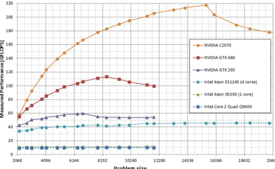
Traditionally, the use ofGPUswas limited to computing graphics or image processing [11]. In recent years, nevertheless, has begun to use, such processors, for computing applications where traditionally general-purposeCPUsare used. Currently, though graphics processors are designed primarily for generation of 3D graphics, fulfil certain characteristics that make them very attractive for computing, for example in science or simulation. Between these features, we can highlight a high level of parallelism and optimization for floating point calculations. The Figure 3.2 illustrate the results of a benchmark made between GPUs and CPUs that shows how GPU performance is greater than CPU performance while increasing the size of the problem. With a higher performance value, indicating that a problem of a certain size will be solved more quickly.
Heterogeneous computing refers to systems that use more than one kind of processor. These are multi-core systems that gain performance not just by adding cores, but also by incorporating specialized processing capabilities to handle particular tasks. Heterogeneous System Architecture utilize multiple processor types (typicallyCPUsandGPUs), usually on the same silicon die, to give the best of both worlds: GPU processing, apart from its well known 3D graphics rendering capabilities, can also perform mathematically intensive computations on very large data sets, while CPUs can run the operating system and perform traditional serial tasks.
The drive to improve performance and the continuing constraints on power and scalability in multi-core CPU development have led semiconductor, software and systems designers increasingly to look to the vector processing capabilities ofGPUs. Vector processors like those in advanced GPUs have up to thousands of individual compute cores, which can operate simultaneously. This makes GPUs ideally suited for computing tasks that deal with a combination of very large data sets and intensive numerical computation.
Figure 3.2: Performance benchmark between GPUs and CPUs
3.1.1 GPU Architecture
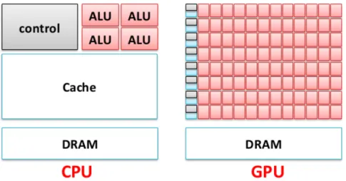
One might ask why there is such a large performance gap between GPUs and general-purpose CPUs. The answer lies in the differences design philosophies between the two type of processors, as illustrated inFigure3.3. The design of theCPU is designed for the sequential code performance. It makes use of sophisticated control logic to allow instruc-tions from a single thread of execution to execute in parallel or even out of their sequential order while maintaining the appearance of sequential execution. More importantly, large cache memories are provided to reduce the instruction and data latencies of large complex applications. Neither control logic nor cache memories contribute to the peak calculation speed.
In contrast, the design philosophy of theGPUsis shaped by the fast growing video game industry, which exerts tremendous economic pressure for the ability to perform a massively number of floating-point calculations per video frame in games. This demand, motivates theGPUvendors to look for ways to maximize the chip area and power budget dedicate to floating-point calculations. The prevailing solution, to date, is to optimize the execution throughput of massive number of threads. The hardware takes advantage of a large number of execution threads to find work to do when some of them are waiting for long-latency memory accesses, thus minimizing the control logic required for each execution thread. Small cache memories are provided to help control the bandwidth requirements of these applications that multiple threads that access the same memory data do not need to all go to the main memory. As a result, much more chip area is dedicated to the floating-point calculations.
op-Figure 3.3: CPUs and GPUs: different design philosophy
erating approximately 10 times the bandwidth of available CPU chips. This is because of frame buffer requirements and the relaxed memory model (the way various system software, applications, and I/O devices expect their memory accesses to work). General-purpose processors have to satisfy requirements from operating system, applications, I/O devices that make memory bandwidth more difficult to increase. In contrast, with simpler memory models, theGPUdesigners can easily achieve more higher memory bandwidth. 3.1.2 CPU-GPU Connection
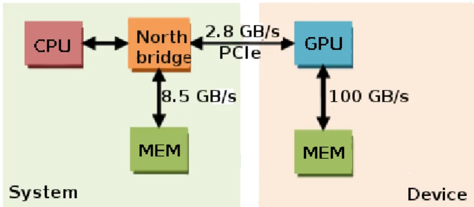
TheGPUexecutes independently from theCPUbut is controlled by theCPU. Application programs running on theCPUuse graphicsAPI, runtime, and driver software components to communicate with theGPU. Most of the communication involves placing commands or data in memory buffers and transmitting them to the GPU. Graphical data that are accessed frequently (Such as vertices, textures, output images) by the GPU are often placed in a high-bandwidth memory attached directly to theGPU, with the CPU being used to set the initial state of these objects. Even with the dedicated GPU memory, the CPUsends a great deal of data to theGPUon behalf of the application. Modern PCs use thePCIebus [23] to connect theCPU and theGPU.PCIeis a scalable bus, divided into serial, bidirectional lanes as illustrated inFigure 3.4.
Entertainment consoles or other dedicated devices use their own interconnect strategy. In the case of consoles, this may offer considerably higher bandwidth than is available through PCIe. In some implementations, the GPU may be integrated into the memory controller chip andCPUmay share the same memory rather than using dedicated memory for the GPU. These integratedGPUs are a popular low-cost alternative to add-in cards. These options provide interesting cost and performance tradeoffs and also affect some of the processing strategies used by the application developer. However, the basic GPU architecture concepts remain unaffected.
Figure 3.4:CPU and GPU interconnection using PCIe with connection bandwidth
3.1.3 Parallel Programming Languages
As GPUs designed for running graphics applications, most of the development for pro-gramming languages and APIs has been targeted at writing graphics applications. This makes non-graphics programming more challenging as the programmer must deal with idioms from the graphics APIs and languages, such as drawing triangles to create a set of domain points and trigger fragment processing across that domain. Shading programs must be written to process the domain points, using texture mapping operations to read data associated with each domain point and writing the computed result as a color value. To simplify this programming task and hide the underlying graphics idioms, several pro-gramming languages and rutines have been created. These range from systems from graphics vendors that expose low-level details of the underlying graphics hardware imple-mentation (CUDA [3], OpenCL [25]) to research and commercial higher-level languages and systems intended to simplify development of data parallel programs. The ones that are the most widely used areMPI (Message Passing Interface) [14] and OpenMP (Open Multi-Processing) [2]. MPI for scalable cluster computing, is a model where computing nodes in a cluster do not share memory. All data sharing and interaction must be done through explicit message passing. MPIhas been successful in the high-performance scien-tific computing domain. Applications written inMPIhave been known to run successfully on cluster computing systems with more than 100,000 nodes. The amount of effort re-quired to port an application into MPI, however, can be extremely high due to lack os shared memory across computing nodes. OpenMPfor shared-memory multiprocessor sys-tems, supports shared memory, so it offers the same advantage as other graphic language. However, it has not been able to scale beyond a couple hundred computing nodes due to thread management overheads and cache coherence hardware requirements.
Aspects ofCUDAare similar to bothMPIandOpenMPin that the programmer manages the parallel code constructs, although OpenMP compiler do more of the automation in managing parallel execution. Several ongoing research efforts aim to adding more automa-tion of parallelism management and performance optimizaautoma-tion to the CUDA tool chain. OpenCL is similar to CUDA, the OpenCL programming model defines language exten-sions and runtime APIs to allow programmers to manage parallelism and data delivery. OpenCLis a standardized programming model in that applications developed in it can run
without modification on all processors that support the language extensions andAPI. In many cases, the language combines the parts of the code that execute on theCPUand the parts that execute on the GPU in a single program. This differs from many of the graphicsAPIs(such asOpenGL (Open Graphics Library)[22]) that deliberately make the boundary between theCPUand GPU explicit.
One advantage of higher level languages is that they preserve high-level information that can potentially be used by the underlying runtime to manage execution and memory coherence. In contrast, lower level systems leave that largely up to the programmer, re-quiring the programmer to learn various architectural details to approach peak efficiencies. Low-level systems may allow programmers to achieve better performance at the cost of portability, but they also may allow access to newer, more efficient processing constructs that are not currently available in the graphicsAPIs.
3.2 CUDA
3.2.1 Introduction
CUDA is a set of tools (created by nVIDIA) allowing to encode programs for nVIDIA GPUs.
To a CUDAprogrammer, the computing system consists of a host, which is a traditional CPU, such as an Intel architecture microprocessor in personal computers today, and one or more devices, which are massively parallel processors equipped with a large number of arithmetic execution units. In modern software applications, program sections often exhibit a rich amount of data parallelism, a property allowing many arithmetic operations to be safely performed on program data structures in a simultaneous manner. TheCUDA devices accelerate the execution of these applications by picking a large amount of data parallelism.
3.2.2 Data Parallelism Model
Data parallelism is a form of parallelization of computing across multiple processors in parallel computing environments. Data parallelism focuses on distributing the data across different parallel computing nodes. It contrasts to task parallelism as another form of parallelism.
In a multiprocessor system executing a single set of instructions, data parallelism is achieved when each processor performs the same task on different pieces of distributed data. In some situations, a single execution thread controls operations on all pieces of data. In others, different threads control the operation, but they execute the same code. Data parallelism refers to the program property whereby many arithmetic operations can be safely performed on the data structures in a simultaneous manner.
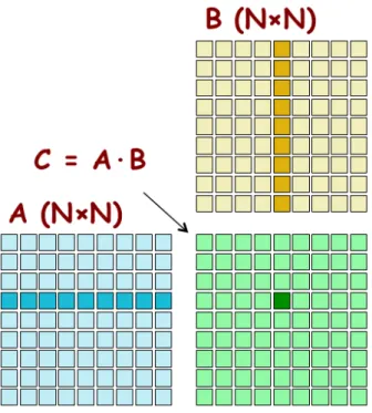
To give an illustration the concept of data parallelism, we give a matrixmatrix multipli-cation example in Figure 3.5. In this example, each element of the product matrix C is generated by performing a dot product between a row of input matrix A and a column of input matrix B. The highlighted element of matrix C is generated by taking the dot product of the highlighted row of matrixAand the highlighted column of matrixB. Note that the dot product operations for computing different matrixC elements can be simul-taneously performed. That is, none of these dot products will affect the results of each other. Therefore, matrix multiplication of large dimensions can have very large amount of data parallelism. For example, a 1000 x 1000 matrix multiplication has 1,000,000 in-dependent dot product. By executing many dot products in parallel, aCUDAdevice can significantly accelerate the execution of the matrix multiplication over a traditional host CPU. Nevertheless, the data parallelism in real applications is not always as simple as that in the matrix multiplication example.
Figure 3.5: Matrix-matrix multiplication example
3.2.3 CUDA Program Structure
A CUDA program consists of one or more phases that are executed on either the host, CPU, or a device such as a GPU. The phases that show little data parallelism are mented in host code. The phases that show rich amount of data parallelism are imple-mented in the device code. A CUDA program is a unified source code comprising both host and device code. Thenvcc (NVIDIA C compiler)separates the two code type during the compilation process. The host code is straight ANSI C code: it is further compiled with the host’s standard C compilers and runs as an ordinary CPU process. The device code is written using ANSI C extended with keywords for labelling data-parallel func-tions, called kernels, and their associated data structures. The device code is typically further compiled by the nvcc and executed on a GPU device. In situations where no device is available or the kernel is more appropriately executed on a CPU, one can also
choose to execute kernels on aCPUusing the emulation features inCUDA SDK (Software Development Kit)or the MCUDA tool [24].
The kernel functions typically generate a large number of threads to exploit data par-allelism. In a problem with a lot of data, the number of threads that will be created will be very large. Would generate more than 1,000,000 threads when it is invoked. It is worth noting that CUDA threads are of much lighter weight than the CPU threads. CUDA programmers can assume that these threads take very few cycles to generate and schedule due to efficient hardware support. This is in contrast with the CPU threads that typically require thousands of clock cycles to generate and schedule. For example, in the matrix-matrix multiplication, the entire matrix multiplication computation can be implemented as a kernel where each thread is used to compute one element of output matrix. In this example, the number of threads used by the kernel is a function of the matrix dimension. For a 1000 x 1000 matrix-matrix multiplication, the kernel that uses one thread to compute one output element would generate 1,000,000 threads.
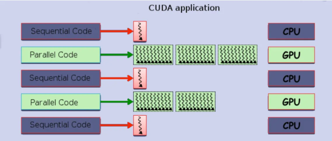
TheFigure3.6illustrate the execution of a typical CUDAprogram. The execution starts with host (CPU) execution. When a kernel function is invoked, the execution is moved to a device (CUDA), where a large number of threads are generated to take advantage of abundant data parallelism. All the threads that are generated by a kernel during an invocation are collectively called a grid (array of threads). When all threads of a kernel complete their execution, the corresponding grid terminates, and the execution continues on the host until another kernel is launched.
Figure 3.6: Execution of a CUDA program
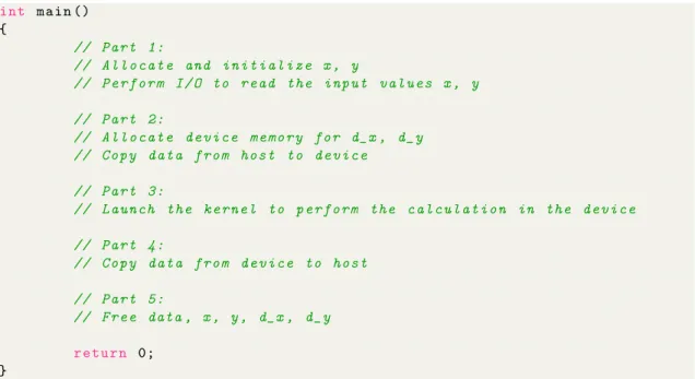
It is worthwhile to introduce a code example that concretely illustrates theCUDAprogram structure. Listing 3.1 shows a simple main function skeleton. The main program first allocates the variables, which will work, in the host memory and then performs I/O to read the values. Then, it allocates memory for each variable in the device and copy data from the host memory to the device memory. At this point, the program is able to perform kernel launch (invoke kernel functions to do calculations in the GPU). Once the kernel execution is finished (after completing the calculations in the device), the main function read the data from the device memory to the host memory and finally, free up all the allocated data.
int m a i n () { // P a r t 1: // A l l o c a t e and i n i t i a l i z e x , y // P e r f o r m I / O to r e a d the i n p u t v a l u e s x , y // P a r t 2: // A l l o c a t e d e v i c e m e m o r y for d_x , d_y // C o p y d a t a f r o m h o s t to d e v i c e // P a r t 3:
// L a u n c h the k e r n e l to p e r f o r m the c a l c u l a t i o n in the d e v i c e
// P a r t 4: // C o p y d a t a f r o m d e v i c e to h o s t // P a r t 5: // F r e e data , x , y , d_x , d_y r e t u r n 0; }
Listing 3.1: A simple CUDA program structure
As we can see, part 3 performs a kernel launch. We will explain how to do this operation as well as we will give a full example in the Section 3.2.5 (both the host code and the device code).
3.2.4 Device Memories and Data Transfer
In CUDA, the host and devices have separate memory spaces. This reflects the reality that devices are typically hardware cards that come with their own memory GDRAM (Graphical Dynamic Random Access Memory). In order to execute a kernel on a device, the programmer needs to allocate memory on the device and transfer pertinent data from the host memory to the allocated device memory. Similarly, after device execution, the programmer needs to transfer result data from the device memory back to the host memory and free up the device memory that is no longer needed. The CUDA runtime system providesAPI functions to perform these activities on behalf of the programmer.
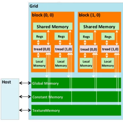
Figure 3.7 shows an overview of the CUDA device memory model for programmers to
reason about the allocation, movement, and usage of the various memory types of a device. At the bottom of the figure, we see: global memory, constant memory and texture memory. These are the memories that the host code can transfer data to and from the device, as illustrated by the bidirectional arrows between these memories and the host. Registers, shared memory and local memory are on-chip memories. Variables that reside in these types of memory can be accessed at very high speed in a highly parallel manner.
• Global memory
Figure 3.7: CUDA device memory model
in the device. When a warp1 executes an instruction that accesses global memory board requests from around the warp in one or many transactions depending on the size of the memory accesses. Access time of the memory is high, so we need a very high number of accesses to mask latency. Is a read-write memory.
• Constant memory
Constant memory supports short-latency, high-bandwidth, read-only access by the device code when all threads simultaneously access the same location. This is where constants and kernel arguments are stored.
• Texture memory
This memory advantage memory used in the graphics pipeline for computational uses. Specifically, texture memory is cache optimized for 2D spatial access pattern. • Local memory
Does not physically exist. It is an abstraction to the local scope of a thread. Actually put in global memory by the compiler. Used for whatever does not fit into registers. • Shared memory
1
A warp in CUDA is a group of 32 threads, which is the minimum size of the data processed in SIMD by a CUDA multiprocessor
Shared memory resides in the chip, therefore has a higher bandwidth and lower latency than the local and global memories. To achieve a higher bandwidth, the memory is divided into banks. Any request for reading/writing of n addresses that fall in n different banks can still be served simultaneously. As a result, we have that the optimal bandwidth is n times the bandwidth of a single bank. But if you have two requests to the same bank, is a conflict that must be serialized.
Shared memory is allocated to thread blocks. All threads in a block can access variables in the shared memory locations allocated to the block. Shared memory is an efficient means for threads to cooperate by sharing their input data and the intermediate results of their work.
• Registers
Registers are allocated to individual threads. Each thread can only access its own registers. A kernel function typically uses registers to hold frequently accessed vari-ables that are private to each thread.
By declaring aCUDAvariable in one of theCUDAmemory types, the programmer dictates the visibility and access speed of the variable. Table 3.1 presents the CUDA syntax for declaring program variables into the various types of device memory. Each such declaration also gives its declaredCUDA variable a scope and lifetime.
Variable Declaration Memory Scope Lifetime
Automatic variables other than arrays Register Thread Kernel Automatic array variables Local Thread Kernel
device shared int var Shared Block Kernel
device int var Global Grid Application
device constant int var Constant Grid Application
Table 3.1:CUDA variable qualifiers type
Scope identifies the range of threads that can access the variable: by a single thread only, by all threads of a block, or by all threads of all grids. If the scope of a variable is a single thread, a private version of the variable will be created for every thread. Each thread can only access its private version of the variable. For example, if a kernel declares a variable whose scope is a thread and it is launched with 1 million threads, then 1 million versions of the variable will be created so each thread initializes and uses its own version of the variable.
Lifetime specifies the portion of the program’s execution duration when the variable is available for use: either within a kernel’s invocation or throughout the entire application. If a variable’s lifetime is within a kernel invocation, it must be declared within the kernel function body and will be available for use only by the kernel’s code. If the kernel is invoked several times, the contents of the variable are not maintained across these invocations. Each invocation must initialize the variable in order to use them. On the other side, if a variable’s lifetime is throughout the entire application, it must be declared outside of any
function body. The contents of the variable are maintained throughout the execution of the application and are available to all kernels.
3.2.5 Kernel Functions
InCUDA, a kernel function specifies the code to be executed by all threads during a parallel phase. Because all of these threads execute the same code, CUDA programming is an instance of the well-known single-program, multiple-data (SPMD) parallel programming style, a popular programming style for massively parallel computing systems.
Listing 3.2 shows a simple kernel function. The syntax is ANSI C with some notable
extensions. First, there is aCUDA specific keyword global in front of the declaration of the function name. This keyword indicates that the function is a kernel and that it can be called from a host functions to generate a grid of threads on a device.
_ _ g l o b a l _ _ v o i d v e c a d d (int N , f l o a t * x , f l o a t * y , f l o a t * c ) {
int idx = b l o c k I d . x * b l o c k D i m . x + t h r e a d I d x . x ;
if ( i < N ) c [ idx ] = x [ idx ] + y [ idx ]; }
Listing 3.2: A simple CUDA kernel function
In general, CUDA extends C function declarations with three qualifier keywords. The meanings of these keywords are summarized inTable3.2. The global keyword indicates that the function being declared is aCUDAkernel function. The function will be executed on the device and can only be called from the host to generate a grid of threads on a device. We will show the host code syntax for calling a kernel function later. Moreover global , there are two other keywords that can be used in front of a function declaration.
Declaration Executed on Only callable from device float devFunc() device device
global void kernel() device host
host float hosFunc() host host
Table 3.2: CUDA extensions to C functional declaration.
Following with the table, The device keyword indicates that the function being declared is aCUDA device function. A device function executes on a CUDA device and can only be called from a kernel function or another device function. Device functions can have neither recursive function calls nor indirect function calls through pointers in them. The
host keyword indicates that the function being declared is aCUDA host function. A host function is simply a traditional C function that executes on the host and can only be called from another host function. By default, all functions in aCUDA program are host functions if they do not have any of theCUDA keywords in their declaration.
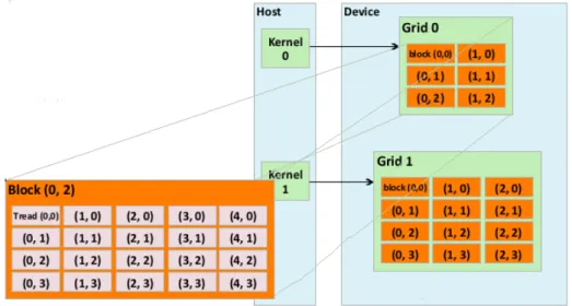
When a kernel is invoked, it is executed as grid of parallel threads. In Figure xx, the launch of kernel 1 creates grid 0 (As shown in Figure 3.8. Each CUDA thread grid
typically is comprised of thousands to millions of GPU threads per kernel invocation. Creating enough threads to fully utilize the hardware often requires a large amount of data parallelism. Threads in a grid are organized into a two-level hierarchy. At the top level, each grid consists of one or more thread blocks. All blocks in a grid have the same number of threads. Each block has a unique two-dimensional coordinate given by the CUDAspecific keywordsblockIdx.x andblockIdx.y. All thread blocks must have the same number of threads organized in the same way.
Figure 3.8: CUDA thread organization
Each thread block is, in turn, organized as a three-dimensional array of threads with a total size of up to 512 threads. The coordinates of threads in a block are uniquely defined by three thread indices given by the CUDA specific keywords: threadIdx.x, threadIdx.y, andthreadIdx.z.
When the host code invokes a kernel, it sets the grid and thread block dimensions via
execution configuration parameters. This is illustrated in Listing lst:cuda-kernel-invoke. To call the kernel function, we must specify two parameters. The first, dimBlock, is for describing the configuration of blocks. The second,dimGrid, describes the configuration of the grid. And finally, the final line of code invokes the kernel. The special syntax between the name of the kernel function and the traditional C parameters of the function surrounded by¡¡¡ and¿¿¿is a CUDAextension to ANSI C. It provides the dimensions of the grid in terms of number of blocks and the dimensions of the blocks in terms of number of threads. u n s i g n e d int nw = ( N + 2 5 5 ) / 2 5 6 ; // C o n f i g u r a t i o n d i m 3 d i m B l o c k (256 , 256 , 1) ; d i m 3 d i m G r i d ( nw , nw , 1) ; // I n v o k e k e r n e l
vecadd < < < dimGrid , d i m B l o c k > > >( N , d_x , d_y , d_c ) ;
A complete example of code is shown inListing 3.4. This piece of code illustrates all the concepts we have been explained in this section.
_ _ g l o b a l _ _ v o i d v e c a d d (int N , f l o a t * x , f l o a t * y , f l o a t * c ) {
int idx = b l o c k I d . x * b l o c k D i m . x + t h r e a d I d x . x ;
if ( i < N ) c [ idx ] = x [ idx ] + y [ idx ]; } int m a i n () { // P a r t 1: A l l o c a t e x , y , c u n s i g n e d int l e n g t h = N * s i z e o f(f l o a t) ; f l o a t* h_x = (f l o a t*) m a l l o c ( l e n g t h ) ; f l o a t* h_y = (f l o a t*) m a l l o c ( l e n g t h ) ; f l o a t* h_c = (f l o a t*) m a l l o c ( l e n g t h ) ; // P a r t 2: A l l o c a t e d e v i c e m e m o r y for d_x , d_y , d_c f l o a t* d_x , d_y ; c u d a M a l l o c ((v o i d**) & d_x , l e n g t h ) ; c u d a M a l l o c ((v o i d**) & d_y , l e n g t h ) ; c u d a M a l l o c ((v o i d**) & d_c , l e n g t h ) ; // P a r t 3: i n i t i a l i z e x , y r e a d ( x ) ; r e a d ( y ) ; // P a r t 4: T r a n s f e r d a t a to d e v i c e c u d a M e m c p y ( d_x , h_x , length , c u d a M e m c p y H o s t T o D e v i c e ) ; c u d a M e m c p y ( d_y , h_y , length , c u d a M e m c p y H o s t T o D e v i c e ) ;
// P a r t 5: L a u n c h k e r n e l to do c a l c u l a t i o n in the d e v i c e // C o n f i g u r a t i o n u n s i g n e d int nw = ( N + 2 5 5 ) / 2 5 6 ; d i m 3 d i m B l o c k (256 , 256 , 1) ; d i m 3 d i m G r i d ( nw , nw , 1) ; // I n v o k e k e r n e l
vecadd < < < dimGrid , d i m B l o c k > > >( N , d_x , d_y , d_c ) ;
// P a r t 6: T r a n s f e r d a t a to h o s t c u d a M e m c p y ( h_c , d_c , length , c u d a M e m c p y D e v i c e T o H o s t ) ; // P a r t 7: Use r e s u l t s u s e f u l ( h_c ) ; // P a r t 8: F r e e data , x , y , c h o s t f r e e ( h_x ) ; f r e e ( h_y ) ; f r e e ( h_c ) ; // P a r t 9: F r e e d a t a d_x , d_y , d_c d e v i c e
c u d a F r e e ( d_x ) ; c u d a F r e e ( d_y ) ; c u d a F r e e ( d_c ) ;
r e t u r n 0; }
Listing 3.4: A complete CUDA application
3.2.6 CUDA Threads
As seen so far,CUDA threads are organized hierarchically to facilitate the programming of applications that automatically scale depending on the number of processors or cores. The basic unit of this hierarchy is the thread, which as explained, that just running the kernel source coordinating with other threads. Also seen how these threads have a unique identifier to distinguish themselves from each other and to identify the appropriate portion of the data to process. These threads are organized into a two-level hierarchy using unique coordinates: blockIdx (for block index) andthreadIdx (for thread index), assigned to them by theCUDA runtime system.
When a thread executes the kernel function, references to the blockIdx and threadIdx
variables return the coordinates of that thread. Additional built-in variables,gridDimand
blockDim, provide the dimension of the grid and the dimension of each block respectively. In general, a grid is organized as a 2D array of blocks. Each block is organized into a 3D array of threads. The exact organization of a grid is determined by the execution configuration provided at kernel launch.
CUDAallows threads in the same block to coordinate their activities using a barrier syn-chronization function, syncthreads(). When a kernel function calls syncthreads(), the thread that executes the function call will be held at the calling location until every thread in the block reaches the location. This ensures that all threads in a block have completed a phase of their execution of the kernel before any moves on to the next phase. Barrier synchronization is a simple and popular method of coordinating parallel activities. Once a grid is launched, its blocks are assigned to streaming multiprocessors in arbitrary order, resulting in transparent scalability ofCUDAapplications. The transparent scalabil-ity comes with the limitation that threads in different blocks cannot synchronize with each other. The only safe way for threads in different blocks to synchronize with each other is to terminate the kernel and start a new kernel for the activities after the synchronization point.
3.2.7 CUDA vs. OpenCL
OpenCL is a standardized, cross-platform, parallel-computing API based on the C lan-guage. It is designed to enable the development of portable parallel applications for systems withheterogeneouscomputing devices.
reflects its support for multi-platform and multi-vendor portability. Whereas theOpenCL standard is designed to support code portability across devices produced by different ven-dors, such portability does not come free. OpenCL programs must be prepared to deal with much greater hardware diversity and thus will exhibit more complexity. Also, many OpenCL features are optional and may not be supported on all devices, so a portable OpenCLcode must avoid using these optional features. Some of these optional features, though, allow applications to achieve significantly more performance in devices that sup-port them.
OpenCLemploys a data parallelism model that has direct correspondence with theCUDA data parallelism model. An OpenCLprogram consists of two parts: kernels that execute on one or moreOpenCLdevices and a host program that manages the execution of kernels.
Figure3.9summarizes the mapping ofOpenCLdata parallelism concepts to theirCUDA
equivalents.
Figure 3.9: Mapping between OpenCL and CUDA concepts
Like CUDA, the way to submit work for parallel execution in OpenCL is for the host program to launch kernel functions. OpenCL kernels have identical basic structure as CUDA kernels. All OpenCL kernel function declarations start with a kernel keyword, which is quivalent to the global keyword in CUDA.
GMAC
4.1 Introduction
Programming models likeCUDAandOpenCLpresent different memories to the program-mer, which is responsible for memory arrangement in a given space and perform explicit data transfers between these different spaces. These programming models suppose that data structures that reside in the memory are closest to the computation unit (either the processor of the CPU or the accelerator) to perform computations more efficiently. Pro-grammers are, furthermore, responsible for managing the consistency of memory. This approach prevents kernels has parameters passed by reference and instead of returning a pointer (to save bandwidth) have to return all the resulting structure.
Therefore, providing the programmer an interface that requires an unique allocation (an unique address space) and eliminate the need for explicit transfer, would increase the programmability and portability of applications forheterogeneous systems. Bearing that in mind, was bornGMAC library.
GMAC is a user-level library that provides a programming model that attempts to facil-itate the programming of accelerator-based systems, such as systems with GPUs. This model basically abstracts the developer from the peculiarities of each particular system and proposes a simple API to replace the host code for devices management for a more generic one. This allows, for example, the execution of CUDA or OpenCL code on the same host with the same code (no need to change the code).
Some important features that the model give us are:
• Unification of the various system memories (asymmetric distributed shared memory [6]).
• Compatibility with CUDA and OpenCL.
• Information about system topology (PCIeinterconnection, sockets number, memory access bandwidth, etc.).
• System hardware abstraction and its peculiarities. • Transparently exploits the system hardware capacities.
• Increment the portability between different systems.
4.2 Overall Design
GMAC is composed of several layers that give each one a certain level of abstraction of the system. Most important that are shown inFigure4.1are:
Figure 4.1: GMAC overall design
• HAL (Hardware Abstraction layer). Implements a set of operations to obtain, store and execute kernel in heterogeneous architectures. Thanks to this layer, the programmer has a hardware abstraction layer.
• DSM (Distributed Shared Memory). Implements a memory manager coherence between different address spaces with operations Acquire/Release. It abstracts us for making explicit data copies between different address spaces.
• ULAS (Unified Logical Address Space). Provides a single logical address space for all the memories.
• System-level programming model. This can be any programming language. • Backend. Such asCUDAorOpenCL. The backends are a layer that is under HAL,
which implement the abstraction layer.
4.3 Memory Model
GMAC memory model is based on the use of multiple virtual address spaces to define which objects can be accessed from devices (as illustrated inFigure4.2). Given that each device has its own physical address space (local memory), it allows the creation of virtual address space for each device. In addition,GMAC allows the programmer to create data objects that can be mapped in one or multiple existent virtual address spaces. Thus, the programmer can easily define which objects are visible to each device. All objects can be
accessed by any of the system devices andGMAC transparently handles remote access or data replication.
Figure 4.2: GMAC memory model
When an object is mapped in a virtual address space, you get a view. This view allows you to define certain properties about data visibility, such as the ability to read or write, or the behaviour of the coherence protocol.
Needless to say that GMAC also provides optimizations for memory access in a trans-parent manner and the programmer does not have to worry about, for example, to make transferences to the device using ”Pinned” memory or exploit certain characteristics of a particularGPU model.
4.4 Execution Model
GMACallows the creation of different execution context for each virtual device. These con-texts can be created from a virtual address space, allowing, creating multiple independent execution contexts. This allows you to run different kernels on one GPU independently and therefore its execution can be parallelized.
4.5 GMAC code example
Before giving an example, in Figure 4.3the two models (CUDA and GMAC) are shown and what steps to follow to create an application.
If we compare them, CUDA has to allocate memory for both the CPU and GPU. It also has to do data transfers between theCPUand GPUand vice versa when the job finished. At the end of the program, you need to free the memory for both theCPU as the GPU. In contrast,GMAC only needs one memory allocation. No need to do memory transfers, manually by the developer, butGMAC is responsible internally in a timely manner. And at the end of the program, you just need to free the memory that has been reserved. As noted in the figure, the kernel is the same for bothCUDAandGMACand will not change. Thus, programming is simplified significantly usingGMAC.
Figure 4.3: Programming step overview
It is worthwhile to introduce a code example that concretely illustrate aGMAC program structure. Listing 4.1 show an easy GMAC code to illustrate what we explained in this chapter.
As we can see in the code, there is no need to perform memory copy action between the host and the device manually. Also we don’t need to create a duplicated references to a variables, with only one reference to a variable is enough.
With only call (gmacMalloc()), GMAC is capable to handle all these actions internally; perform memory copy when needed, create only one pointer.
int m a i n () { // P a r t 1: A l l o c a t e x , y , c u n s i g n e d int l e n g t h = N * s i z e o f(f l o a t) ; f l o a t* x , y , c ; g m a c M a l l o c ((v o i d **) & x , l e n g t h ) ; g m a c M a l l o c ((v o i d **) & y , l e n g t h ) ; g m a c M a l l o c ((v o i d **) & c , l e n g t h ) ; // P a r t 2: i n i t i a l i z e x , y r e a d ( x ) ; r e a d ( y ) ; // P a r t 3: L a u n c h k e r n e l to do c a l c u l a t i o n in the d e v i c e // C o n f i g u r a t i o n u n s i g n e d int nw = ( N + 2 5 5 ) / 2 5 6 ; d i m 3 d i m B l o c k (256 , 256 , 1) ; d i m 3 d i m G r i d ( nw , nw , 1) ; // I n v o k e k e r n e l vecadd < < < dimGrid , d i m B l o c k > > >( N , x , y , c ) ; // P a r t 4: Use r e s u l t s u s e f u l ( c ) ; // P a r t 5: F r e e data , x , y , c g m a c F r e e ( x ) ; g m a c F r e e ( y ) ; g m a c F r e e ( c ) ;
r e t u r n 0; }
Listing 4.1: A GMAC application
Comparing the code shown above with the one shown in the last chapter (Listing 3.4), we can see that the code written inGMAC is much simpler than code written inCUDA. In the above code, the relevant parts that it save are: memory allocation (If memory is reserved on both devices, duplicate pointers are created) and data transfer to and from the device.
Design and Implementation
After defining what improvements should be added to the library, has begun implementing them.
First of all we have seen that we need to implement a memory coherence protocol (ex-plained in Section 5.2).But before implement this protocol, we have to implement the virtual space that devices share (explained inSection 5.1).
5.1 Shared Address Space
GMACbuilds a shared address space between theCPUsandGPUs. When an application requests memory (viagmacMalloc()), accelerator memory is allocated on the accelerator, returning a memory address that can be used only by the accelerator. Then, the library request the operating system to allocate system memory over the same range of virtual memory addresses. To carry out this, is done by an operating system call, which accepts a virtual address and maps it to an allocated range of system memory. At this point, two identical memory addresses ranges have been allocated, one in theGPU memory and the other in the CPU memory. Hence, a single pointer can be returned to the application to be used by both code (CPUand GPU). Therefore, with a simple memory request call
(gmacMalloc()), GMAC can give to the programmer a single reference to the memory
instead of two references.
Until now, the memory range created is an unique block. Internally it’s treated as an unique block in which all the operations are performed in it. This can cause problems when dealing with memory coherence (explained in the next section). For example, when a device writes in the start of the block, is necessary to invalidate the whole range in other devices and send them, if necessary, the new data. Even if another device only reads and writes in a part at the end of the block. This phenomenon is called false sharing. Two or more devices share the same memory range, but no other part overlap each other. But the protocols when managing the memory consistency, the whole range is treated as if it was just one.
The solution to this problem, is to divide the range in blocks where every block has the same length. We have decided that the block length should be the page size of the system memory. By doing this, we had to review the entire DSM layer, adapt all the existing functions to the new block style as well as create new functions to perform this change.
We illustrate an example in Figure 5.1. As can be seen, in this example, we have three devices namedptr1,ptr2,ptr3 (these devices can be eitherCPUsorGPUs). Each device has its own memory (the blue range for ptr1, green range for ptr2 and orange range for
ptr3) and then when two devices want to create a shared space, the responsible function, creates a mapping between these two memory spaces (in the picture looks purple). The created mapping, is divided into parts of equal size and fixed length, called blocks. It may happen that a third device wants to create a shared space with another device that is already mapped with another. Then, a second mapping is created with these two devices. These blocks can be created in different mappings. In our example, we created two mappings, them1: between ptr1 and ptr2; and m2: betweenptr2 and ptr3. Therefore, theb1 and b4 block are only in m1 mapping, while blocks b2 and b3 are in m1 and m2
mapping.
Figure 5.1: Shared address space. Mapping and blocking
To keep all this information, we had to create data structures. We have created a structure in the mapping, to know what blocks has the mapping and the information associated with them. We have also created a structure on the block to know what mappings are assigned to it.
Within the DSM layer, functions that are responsible for creating the mapping between the different memory spaces and to decouple these spaces are: linkand unlink.
• Function link. This function receives the following parameters, creates a mapping between the spaces of the two devices and returns a code corresponding to the operation result. This result can be classified in two categories: correct or incorrect. But within the result of incorrect, there are several codes depending on the error. The error might be one of those shown in Listing 5.3.
In Listing 5.1, we show the prototype for the link function. Each parameter is
explained in the code. e r r o r l i n k (
hal :: ptr dst , // P o i n t e r of the f i r s t d e v i c e hal :: ptr src , // P o i n t e r of the s e c o n d d e v i c e
s i z e _ t count , // The l e n g t h of the m e m o r y r a n g e t h a t we w a n t r e s e r v e . F r o m t h i s l e n g t h b l o c k s are c r e a t e d
G m a c P r o t e c t i o n protDst , // W h a t t y p e of p r o t e c t i o n w i l l h a v e the m e m o r y r a n g e for the f i r s t d e v i c e . Can be e i t h e r R e a d or w r i t e
G m a c P r o t e c t i o n protSrc , // W h a t t y p e of p r o t e c t i o n w i l l h a v e the m e m o r y r a n g e for the s e c o n d d e v i c e . Can be e i t h e r R e a d or w r i t e
int f l a g s = m a p p i n g _ f l a g s :: M A P _ D E F A U L T // In t h i s r e l e a s e are not u s e d
)
Listing 5.1: Prototype of link function
• Function unlink. This function receives the following parameters, undoes the mapping between two devices returns a code corresponding to the operation result. This result can be classified in two categories: correct or incorrect. But within the result of incorrect, there are several codes depending on the error. As mentioned earlier, the error might be one of those shown in Listing 5.3.
In Listing 5.2, we show the prototype for the unlink function. Each parameter is explained in the code.
e r r o r u n l i n k (
hal :: ptr mapping , // P o i n t e r of the d e v i c e w h i c h we w a n t to u n d o e s the m a p p i n g
s i z e _ t c o u n t // The l e n g t h of the m e m o r y r a n g e t h a t we w a n t to u n d o e s
)
Listing 5.2:Prototype of unlink function
As mentioned, this class, has all the error type that we handle in our layer. If an error code doesn’t exists in this class, simple add it to it.
# i f n d e f G M A C _ D S M _ E R R O R _ H _ # d e f i n e G M A C _ D S M _ E R R O R _ H _ n a m e s p a c e _ _ i m p l { n a m e s p a c e dsm { e n u m c l a s s e r r o r { D S M _ S U C C E S S = 2000 , D S M _ E R R O R _ I N V A L I D _ A L I G N M E N T = 2001 , D S M _ E R R O R _ I N V A L I D _ P T R = 2002 , D S M _ E R R O R _ I N V A L I D _ V A L U E = 2003 , D S M _ E R R O R _ I N V A L I D _ P R O T = 2004 , D S M _ E R R O R _ O W N E R S H I P = 2005 , D S M _ E R R O R _ P R O T O C O L = 2006 , D S M _ E R R O R _ H A L = 2 9 9 9 }; }} # e n d i f
5.2 Memory Coherence Protocol
To keep all the system information consistent and consistent with all devices on the system, the library must have a memory coherence protocol. We have chosen the MSI protocol because the purpose for which we want, it fits our needs perfectly.
The GMAC coherence protocol is defined from the CPU perspective. All booking and data transfers are managed by the CPU. The GPU (or accelerator) don’t perform any memory consistency or coherence actions. In our system, this protocol works at a block level (as mentioned in the last section).
MSI stands for: Modified-Shared-Invalid. The protocol maintains the following invariant: each block of memory is always in exactly one of the following states:
– I (Invalid). Means that the block is only inGPU (or accelerator) memory and must be transferred back if the CPUreads this block after the accelerator kernel returns. – M (Modified). Means that theCPUhas an updated copy of the block and this block
must be transferred back to the accelerator when the accelerator kernel is called.
– S (Shared). Means that both the CPU and the GPU have the same version of the
data so the block does not need to be transferred before the next method invocation on the accelerator.
To maintain this invariant the MSI protocol forces state transitions as dictated by the following state machine (Figure 5.2), which shows the state of the memory block with respect to a single device. All edges are labelled with the activity that causes the transition. Any value after the / represents an action place on the bus.
Figure 5.2: MSI protocol The local device is capable of performing the following actions: