Masking Large Keys in Hardware:
A Masked Implementation of McEliece
Cong Chen1, Thomas Eisenbarth1, Ingo von Maurich2, and Rainer Steinwandt3
1 Worcester Polytechnic Institute, Worcester, MA, USA
{cchen3,teisenbarth}@wpi.edu
2 Ruhr-Universit¨at Bochum, Germany
3 Florida Atlantic University, USA
Abstract. Instantiations of the McEliece cryptosystem which are considered computationally secure even in a post-quantum era still require hardening against side channel attacks for practical applications. Recently, the first differential power analysis attack on a McEliece cryptosystem successfully recovered the full secret key of a state-of-the-art FPGA implementation of QC-MDPC McEliece. In this work we show how to apply masking countermeasures to the scheme and present the first masked FPGA implementation that includes these countermeasures. We validate the side channel resistance of our design by practical DPA attacks and statistical tests for leakage detection.
Keywords: Threshold Implementation, McEliece Cryptosystem, QC-MDPC Codes, FPGA
1 Motivation
Prominent services provided by public-key cryptography include signatures and key encapsulation, and their security is vital for various applications. In addition to classical cryptanalysis, quantum computers pose a potential threat to currently deployed asymmetric solutions, as most of these have to assume the hardness of computational problems which are known to be feasible with large-scale quantum computers [18]. Given these threats, it is worthwhile to explore alternative public-key encryption schemes that rely on problems which are believed to be hard even for quantum computers, which might become reality sooner than the sensitivity of currently encrypted data expires [5]. The McEliece cryptosystem [12] is among the promising candidates, as it has withstood more than 35 years of cryptanalysis. To that end, efficient and secure implementations of McEliece should be available even nowadays. The QC-MDPC variant of the McEliece scheme proposed in [13] is a promising efficient alternative to prevailing schemes, while maintaining reasonable key sizes. The first implementations of QC-MDPC McEliece were presented in [10], and an efficient and small hardware engine of the scheme was presented in [19]. However, embedded crypto cores usually require protection against the threat of physical attacks when used in practice. Otherwise, side channel attacks can recover the secret key quite efficiently, as shown in [6].
of external randomness needed by the engine is considerably reduced when compared to other TI-based implementations. Our design is fully implemented and analyzed for remaining side channel leakage. In particular, we validate that the DPA attack of [6] is no longer feasible. We further show that there are also no other remaining first-order leakages nor other horizontal leakages as exploited in [6].
After introducing necessary background in Section 2, we present the masked McEliece engine in Sections 3 and 4. Performance results are presented in Section 5. A thorough leakage analysis is presented in Section 6.
2 Background
In the following we introduce moderate-density parity-check (MDPC) codes and their quasi-cyclic (QC) variant with a focus on decoding since we aim to protect the secret key. Afterwards we summarize how McEliece is instantiated with QC-MDPC codes as proposed in [13]. As our work extends an FPGA implementation of QC-MDPC McEliece that is unprotected against side channel attacks [19], we give a short overview of the existing implementation and summarize relevant works on the masking technique of threshold implementations.
2.1 Moderate-Density Parity-Check Codes
MDPC codes belong to the family of binary linear [n, k] error-correcting codes, where n is the length,kthe dimension, andr =n−kthe co-dimension of a codeC. Binary linear error-correcting codes are equivalently described either by their generatorGor by their parity-check matrixH. The rows of generator matrix G ∈ Fk2×n form a basis of C while H ∈ Fr
×n
2 describes the code as the kernel C ={c ∈Fn
2|HcT = 0⊥} where 0⊥ represents an all-zero column vector. The syndrome of any vectorx∈Fn
2 is defined ass=HxT ∈F2r. Hence, the codeC is comprised of all vectorsx∈Fn2 whose syndrome is zero for a particular parity-check matrix H. MDPC codes are defined by only allowing amoderate Hamming weight w= O(pnlog(n)) for each row of the parity-check matrix. By an (n, r, w)-MDPC code we refer to a binary linear [n, k] code with such a constant row weight
w.
A code Cis called quasi-cyclic (QC) if for some positive integern0>0 the code is closed under cyclic shifts of its codewords by n0 positions. Furthermore, it is possible to choose the generator and parity-check matrix to consist ofp×pcirculant blocks ifn=n0·pfor some positive integerp. This allows to completely describe the generator and parity-check matrices by their first row. If an (n, r, w)-MDPC code is quasi-cyclic withn=n0·r, we refer to it as an (n, r, w)-QC-MDPC code. Severalt-error-correcting decoders have been proposed for (QC-)MDPC codes [1,8,10,11,13,21]. The implementation that we base our work on implements the optimized decoder presented in [10], which in turn is an extended version of the bit-flipping decoder of [8]. Decoding a ciphertextx∈Fn
2, is achieved by:
1. Computing the syndrome s=HxT.
2. Computing the number of unsatisfied parity checks #upc for every ciphertext bit.
3. If #upcexceeds a precomputed thresholdb, invert the corresponding ciphertext bit and add the corresponding column of the parity-check matrix to the syndrome.
2.2 McEliece Public Key Encryption with QC-MDPC Codes
The McEliece cryptosystem was introduced using binary Goppa codes [12]. Instantiating McEliece witht-error-correcting (QC-)MDPC codes was proposed in [13], mainly to significantly reduce the size of the keys while still maintaining reasonable security arguments. The proposed parameters for an 80-bit security level are n0 = 2, n= 9602, r= 4801, w = 90, t= 84, which results in a much more practical public key size of 4801 bit and a secret key size of 9602 bit compared to binary Goppa codes which require around 64 kByte for public keys at the same security level.
The main idea of the McEliece cryptosystem is to encode a plaintext into a codeword using the generator matrix of a code selected by the receiver and to add a randomly generated error vector of weight t to the codeword which can only be removed by the intended receiver. We summarize QC-MDPC McEliece in the following by introducing key-generation, encryption and decryption.
Key-Generation.The parity-check matrixHis the secret key in QC-MDPC McEliece. As the code is quasi-cyclic, the parity-check matrix consists ofn0concatenatedr×rblocksH= (H0|. . .|Hn0−1).
We denote the first row of each of these blocks byh0, . . . , hn0−1 ∈F
r
2. The public key in QC-MDPC McEliece is the corresponding generator matrixG, which is computed fromH in standard form as
G= [Ik|Q] by concatenation of the identity matrix Ik∈Fk2×k with
Q=
(Hn−01−1·H0)T (Hn−01−1·H1)T
· · ·
(Hn−01−1·Hn0−2)
T
.
The key generation starts by randomly selecting first row candidates h0, . . . , hn0−1 ∈RF
r 2 such that the overall row weight (wt) sums up tow=Pn0−1
i=0 wt(hi). Since we intend to generate a code which is quasi-cyclic, the n0 blocks of the parity-check matrix are generated from the first rows by cyclic shifts. The resulting parity-check matrix belongs to an (n, r, w)-QC-MDPC code with
n=n0·r. If the last blockHn0−1 is non-singular, i. e., ifH
−1
n0−1 exists, the public key is computed
as G = [Ik|Q]. Otherwise new candidates for hn0−1 are generated until a non-singular Hn0−1 is
found.
Encryption.A plaintextm∈Fk
2 is encrypted by encoding it into a codeword using the recipient’s public key G and by adding a random error vector e ∈ Fn2 of weight wt(e) ≤ t to it. Hence, the ciphertext is computed as x= (m·G⊕e)∈Fn
2.
Decryption. Given a ciphertextx∈Fn2, the intended recipient removes the error vector efrom x using the secret code description H and a QC-MDPC decoding algorithm ΨH yielding mG. Since G= [Ik|Q], the first kpositions ofmG are equal to the k-bit plaintext.
2.3 FPGA Implementation of QC-MDPC McEliece
When a ciphertext bit is inverted, the corresponding row of the parity-check matrix is added to the syndrome. The DPA presented in [6] shows that the described architecture is vulnerable to an efficient horizontal key recovery attack, since neither the key nor internal states are masked.
2.4 Threshold Implementation
Threshold implementation (TI) is a masking-based technique to prevent first order and higher or-der side channel leakage. Since its introduction in [15], many symmetric cryptosystems have been implemented in TI [2,3,4,14,17]. More importantly, most of these works have performed thorough leakage analysis and have shown that TI actually prevents the promised order leakage (if carefully implemented). Even higher-order leakage, while not prevented, usually comes at a highly increased cost of needed observations. TI performs Boolean secret sharing on all sensitive variables. Compu-tations on the shares are then performed in a way that ensures correctness, maintains uniformity of the shares, and ensures non-completeness of the computation, that is, each sub-operation can only be performed on a strict sub-set of the inputs. A detailed description of TI is available in [15]. We choose TI for McEliece because TI is fairly straightforward to apply and to implement, yet it is effective. Furthermore, large parts of McEliece are linear, and hence cheap to mask using TI. The decoder part, while not linear, is also fairly efficient to mask using TI, as shown in Section 4. At the same time, our implementation avoids several of the disadvantages of TI: Unlike [16], we convert our addition to arithmetic masking once the values get larger, yielding a much more efficient addition engine than one solely relying on TI. By including the pseudorandom mask generation in the crypto core, we significantly cut both the required memory space usually unavoidably introduced by TI as well as the required overhead of random bits consumed by TI engines. Note that the TI-AES engines presented in [3,14] consume about 8000 bits of randomness per encryption, while our engine only consumes 160 bits per decryption.
3 Masking QC-MDPC McEliece
An effective way to counteract side channel analysis is to employ masking. Masking schemes aim to randomize sensitive intermediate states such that the leakage is independent of processed secrets. In QC-MDPC McEliece, the key bits and the syndrome are sensitive values that need to be protected and therefore they must be masked whenever they are manipulated. Similarly, since the decoding operation processes the sensitive syndrome, leakage of the decoder needs to be masked as well.
3.1 Masked Syndrome Computation
As described in Section 2.1, the decoding algorithm begins with the syndrome computation s =
HxT. Both the parity-check matrix H and the syndrome s are sensitive values and can cause side channel leakage. However, since the syndrome computation is a linear operation, masking this operation is simple and efficient. Intuitively, H can be split into two shares, Hm and M such that H = Hm⊕M, by Boolean masking. The mask matrix M is created in correspondence to H, by first generating uniformly distributed random masks for hi, m0, . . . , mn0−1 ∈F
r
Algorithm 1 Masked Error Correction Decoder Input:Hm,M1,M2,sm,ms1,ms2,x,B=b0, ..., bmax−1, max
Output: Error free codewordxor DecodingFailure 1: fori= 0 to max−1do
2: forevery ciphertext bitxj do
3: #upc=SecHW(SecAND(sm, ms1, ms2, Hm,j, M1,j, M2,j))
4: d= (#upc> bi), d∈ {0,1}
5: x=x⊕(d·1j) .Flip thejth bit ofx
6: sm=sm⊕(d·Hm,j⊕d¯·M2,j) .Update syndrome
7: ms1 =ms1⊕M1,j .Update masks
8: ms2 =ms2⊕M2,j⊕( ¯d·M1,j) 9: end for
10: if SecHW(sm, ms1, ms2) == 0then .Check for remaining errors
11: returnx
12: end if .For constant run time, this if-statement can be moved after the for-loop 13: end for
14: returnDecodingFailure
3.2 Masked Decoder
After syndrome computation, the error correction decoder computes the number of unsatisfied parity check equations between the sensitive syndrome and one row of the sensitive parity check matrix. By comparing that number with a predefined threshold (usually denoted b), the decoder decides whether to flip the corresponding bit in the ciphertext. Masking the actual decoding steps is more complex, since both inputs, namely the syndrome and the parity check matrix, as well as the control flow of the decoder can leak sensitive information and thus need to be protected. Unlike the syndrome computation, the decoder performs a binary AND and a Hamming weight computation on sensitive data. Both operations are non-linear and thus need more elaborate protection than just a straightforward Boolean masking. In the following we explain how these operations can be implemented. Algorithm 1 describes the masked version of the decoder. Note that the algorithm has been formulated with a constant execution flow to better represent the intended hardware implementation. Further note that the algorithm and its FPGA implementation exhibit a constant timing behavior (except the number of decoder iterations) and that all key-related variables are masked. The number of decoder iterations can be set to maximum by simply moving the if-statement out of the loop. For the chosen 9602/4801 parameter set, max would be set to 5, increasing the average run time roughly by a factor 2 (cf. [21]).
In Algorithm 1, we make use of two special functions. Function SecAND computes the bitwise AND operation between syndromesand secret keyH in a secure way without leaking any sensitive information. The other function SecHW computes the Hamming Weight of a given vector. Both functions are explained in detail in the following. An all-zero vector with the jth bit equal to 1 is indicated by 1j.
representations of the two inputs, i. e., the syndrome and parity check matrix, need to be extended to a three-share representation.
To achieve a three-share representation of both syndrome and parity check matrix, the masking is expanded in the following way: After syndrome computation as explained in Section 3.1, the syndrome is represented as sm ⊕ms and the secret key is represented as Hm,j ⊕Mj. Next, the syndrome representation is extended assm⊕ms1⊕ms2 and the key asHm,j⊕M1,j⊕M2,j. Here,
ms2 and M2,j are two new uniformly distributed random mask vectors and ms1 is derived as
ms1 =ms⊕ms2 and M1,j =Mj⊕M2,j. The following equations show how to achieve a TI version
of s∧h that satisfies correctness and non-completeness, but not uniformity.
s∧h=(sm⊕ms1 ⊕ms2)∧(Hm,j⊕M1,j⊕M2,j)
=(sm∧Hm,j)⊕(sm∧M1,j)⊕(Hm,j∧ms1)⊕
(ms1 ∧M1,j)⊕(ms1 ∧M2,j)⊕(M1,j∧ms2)⊕
(ms2 ∧M2,j)⊕(ms2 ∧Hm,j)⊕(M2,j∧sm)
(1)
As pointed out in [15], in order to fulfill uniformity, one can introduce additional uniform random masks to mask each share. By introducing two more uniformly random vectorsr1 andr2, the three output shares can be computed as follows. Let shdenote the result of the TI version of the AND operation. Using the equations above,shcan be split into three sharesshi, which are now uniformly distributed thanks to theri and are given as:
sh1=(sm∧Hm,j)⊕(sm∧M1,j)⊕(Hm,j∧ms1)⊕r1
sh2=(ms1∧M1,j)⊕(ms1 ∧M2,j)⊕(M1,j∧ms2)⊕r2
sh3=(ms2∧M2,j)⊕(ms2 ∧Hm,j)⊕(M2,j∧sm)⊕r1⊕r2
(2)
Secure Hamming Weight Computation. In the unprotected FPGA implementation of [19], the Hamming weight computation of sh is performed by looking up the weight of small chunks of shfrom a precomputed table and then accumulating those weights to get the Hamming weight of sh. However, the weight of a chunk is always present in plain and the computation of it can result in side channel leakage that will lead to the recovery of the Hamming weight. Even though the knowledge of the weight does not necessarily recover the chunk value, it still yields information about shand thus the secret keyh.
For a side-channel secure implementation, both the input and the output of a Hamming weight computation for each chunk must be masked. Since the weight of all chunks needs to be accumulated, it is preferable to use Arithmetic masking instead of Boolean masking. For example, the Hamming weight ofsh can be calculated using the following equation:
wt(sh) =
|sh| X
i=1
sh1,i⊕sh2,i⊕sh3,i (3)
where subscript i refers to the i-th bit of each share and |sh|is the length of sh in bits. Using a secure conversion function from Boolean masking to Arithmetic masking [7], each Boolean mask tuple (sh1,i, sh2,i, sh3,i) can be converted to an Arithmetic mask pair (A1,i, A2,i) such thatsh1,i⊕ sh2,i⊕sh3,i =A1,i+A2,i. Then, the Hamming weight of sh can be computed as:
wt(sh) =
|sh| X
i=1
A1,i+A2,i=
|sh| X
i=1
A1,i+
|sh| X
i=1
LO
G
IC
LFSR m1,h1
LFSR m1,h0
LFSR m2,h1
LFSR m2,h0
LFSR syn
h1m
h0m
BRAMkey
sm
ms
BRAMsyn
ct1
ct0
BRAMct
f1
f2
f3
Syndrome computation
Decoding
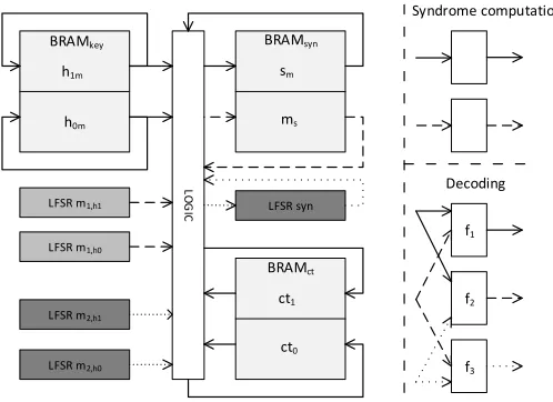
Fig. 1.Abstract block diagram of the masked QC-MDPC McEliece decryption implementation.
According to Equation (4), we only accumulate A1 =P
|sh|
i=1A1,i and A2 =P
|sh|
i=1A2,i, respectively, and sum them up in the end to obtain the total Hamming weight wt(sh) =A1+A2.
Secure Syndrome Checking.In order to test whether decoding of the input vector was successful, the syndrome has to be tested for zero. If the Hamming weight of the syndrome is zero, then all bits of the syndrome must be zero. Otherwise, there must be some bits set as 1 and the number of set bits equals the Hamming weight of the syndrome. Note that we performSecHWoperation over the three shares of syndromesin order to prevent the leakage.
4 Implementing a Masked QC-MDPC McEliece
This section presents more details of the masked FPGA implementation of QC-MDPC McEliece decryption based on the unprotected one in [19]. We follow the structure of the original design, including the same security parameters, but replace vulnerable logic circuits with masked circuits.
4.1 Overview of the Masked Implementation
Each time before the decryption is started, both the ciphertext and the masked secret keysh0m, h1m are written into the BRAMs of the decryption engine. As shown in Figure 1, one BRAM stores the 2·4801-bit ciphertext, the second BRAM stores the 2·4801-bit masked secret key and third BRAM stores the 4801-bit masked syndrome and the 4801-bit syndrome mask. Note that the secret keys are masked before being transferred to the crypto core. The seeds for the internal PRG are transferred with the masked key. Each BRAM is dual-ported, offers 18/36 kBit, and allows to read/write two 32-bit values at different addresses in one clock cycle.
Computations are performed in the same order as in [19]: To compute the masked syndrome
the content of a 32-bit memory cell and then to overwrite it with a new value, all within one clock cycle.
An abstraction of this implementation is depicted in Figure 1. The three block RAMs are used to store the masked keys (h0mand h1m), the shared syndrome (smand ms) and the ciphertext (ct0 and ct1). The LFSR blocks are used to generate the missing masks on-the-fly. The logic blocks for the two phases of the McEliece decryption are shown on the left side of Figure 1.
4.2 Masking Syndrome Computation
The syndrome computation is a linear operation and requires only two shares for sensitive variables. Once the decryption starts, 32-bit blocks of the masked secret keysh0m, h1mare read from the secret key BRAM at each clock cycle and are XORed with the 32-bit block ofsm read from the syndrome BRAM depending on whether the corresponding ciphertext bits are 1. Then the result will be written back into the syndrome BRAM at the next clock cycle and at the same time the rotated 32-bit blocks of the masked keys will be written back into the secret key BRAM. Meanwhile, we need to keep track of the syndrome mask ms. Since syndrome computation is a linear operation, we can similarly add up the secret key masks synchronously to generate the syndrome mask. In our secure engine, we use two 32-bit leap forward LFSRs to generate random 32-bit secret key masks each clock cycle which are XORed with the 32-bit block of ms read from the syndrome BRAM depending on the ciphertext.
Cyclic Rotating LFSRs. Our 32-bit leap forward LFSRs not only generate a 32-bit random mask at each clock cycle but also rotate synchronously with the key. For example, the LFSR for
h0m first needs to generate the 4801-bit maskmh0 in the following sequence: mh0[0 : 31], mh0[32 :
63], . . . , mh0[4767 : 4799], mh0[4800]. This is done in 150 clock cycles. In the next round, the
se-cret key is rotated by one bit as h0m ≫ 1 and hence the mask sequence should be: mh0[4800 :
30], mh0[31 : 62], . . . , mh0[4766 : 4798], mh0[4799]. After 4801 rounds of rotation, the LFSR ends
up with its initial state. In order to construct a cyclic rotating PRG with a period of 4801 bits, we combine a common 32-bit leap forward LFSR with additional memory and circuits, based on the observation that the next state of the LFSR either completely relies on the current state or actually sews two ends of the sequence together, e. g., mh0[4800 : 30]. As shown in Figure 2, five
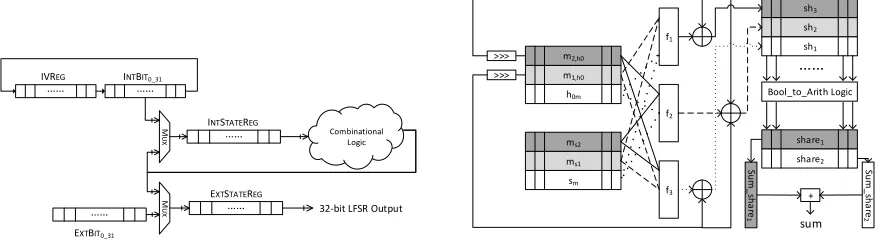
32-bit registers are employed instead of just one. The combinational logic circuit computes the next 32-bit random mask given the input stored in IntStateReg. The following steps describe
the functionality of our LFSR:
1. Initially, the 32-bit seed seed[0 : 31] of the sequence is stored in register IvRegand the first 32
bits of the sequence, e. g., mh0[0 : 31] are stored in the other registers.
2. During the rotation, the combinational logic circuits output the new 32-bit result and feed it back. If the new result is part of the 4801-bit sequence, then it will go through the Mux,
overwriting the current state registers IntStateReg and ExtStateReg at the next clock
cycle.
3. If the new result contains bits that are not part of the sequence, then those bits will be replaced. For example, whenmh0[4767 : 4799] is inIntStateReg, the new result will bemh0[4800 : 4831]
in which only bitmh0[4800] is in the mask sequence andmh0[4801 : 4831] will be dropped. The
Mux gate will only let mh0[4800] go through together with mh0[0 : 30] stored in ExtBit0 31
Combinational Logic
INTSTATEREG
EXTSTATEREG
IVREG
INTBIT0_31
M
UX
EXTBIT0_31
M
UX 32-bit LFSR Output
Fig. 2.The structure of the cyclic rotating LFSR that is used to generate the masks on-the-fly.
h0m m1,h0 m2,h0 sm ms1 ms2 f1 f2 f3 >>> >>> sh1 sh2 sh3 …… Bool_to_Arith Logic share1 share2 Su m _ sh a re 1 Su m _ sh a re 2 + sum
Fig. 3.Layout of our pipelined QC-MDPC McEliece de-coder for the first part of the secret key,h0.
4. mh0[4800 : 30] will not be written into registerIntStateReg because given mh0[4800 : 30] as
input, the combinational logic circuit will not output the next valid statemh0[31 : 62]. Therefore,
we concatenate part of the seed in IvReg and part of the first 32-bits in IntBit0 31, e. g.,
{seed[31], mh0[0 : 30]}and overwriteIntStateReg. Then, the new output will bemh0[31 : 62].
The concatenation is implemented as a cyclic bit rotation as shown in Figure 2. After 32 rotations, the seed is rotated toIntBit0 31and the first 32-bitmh0[0 : 31] is rotated toIvReg.
Hence, they will be swapped back in the next clock cycle.
To sum up, ExtStateReg always contains the valid 32-bit mask while IntStateReg always
contains 32-bit input that results in the next valid state. The rotated secret key is generated in 150 clock cycles. After 4801×150 clock cycles, the LFSR returns to its initial state and idles.
4.3 Masking the Decoder
As mentioned in Section 3, the masked secret keys and the syndrome are extended to three shares. Hence, more LFSRs are instantiated to generate the additional shares as shown in Figure 1. Two LFSRs generate the third shares of h0 and h1, another LFSR generates the third share of the syndrome.
We use h0 as example to describe the decoder, since h1 is processed in parallel using identical logic circuits. We splith0 into three shares:h0mstored in the BRAM andm1,h0 andm2,h0 generated
by two LFSRs. The syndrome is split into sm and ms1 which are stored in BRAM andms2 which
is generated by an LFSR. After decoding is started, each 32-bit share is read or generated at each clock cycle and then SecAND and SecHW are performed. This is implemented using a pipelined approach as shown in Figure 3.
The left part of Figure 3 illustrates the bitwise SecAND operation using Equation (2). The 32-bit shares are fed into shared functions f1, f2, f3, and the outputs are three 32-bit shares of the result. As mentioned before, two additional random vectorsr1, r2 are required to mask the outputs in order to achieve uniformity. Our design uses only two fresh random bitsb1, b2 together with the shifted input shares as the random vectors because the neighboring bits are independent of each other. That isr1 ={b1, m1,h0[0 : 30]} andr2={b2, m2,h0[0 : 30]}. Bothm1,h0[31] andm2,h0[31] are
shifted out and are used asb1 andb2 in the next clock cycle. The right part shows the structure of
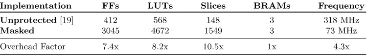
Table I. Resources usage comparison between the unprotected and masked implementations on Xilinx Virtex-5 XC5VLX50 FPGAs.
Implementation FFs LUTs Slices BRAMs Frequency
Unprotected[19] 412 568 148 3 318 MHz
Masked 3045 4672 1549 3 73 MHz
Overhead Factor 7.4x 8.2x 10.5x 1x 4.3x
bit position of the word. We use 32×2 6-bit Arithmetic masked counters1 and each bit in the word sh1⊕sh2⊕sh3 will be added into the corresponding counter during each clock cycle. More specifically, the three shares of each bit of sh are converted and added into the two Arithmetic masked counters. After 150 clock cycles, we sum the overall Arithmetic masked Hamming weight. To convert and accumulate the masked weights, we employ the secure conversion method developed in [7].
5 Implementation Results
The masked design is implemented in VHDL and is synthesized for Xilinx Virtex-5 XC5VLX50 FPGA which holds the crypto engine in the side channel evaluation board SASEBO-GII. The implementation results are listed in Table I in comparison with the unprotected implementation of [19]. In terms of Flip-Flops (FFs) and Look-Up Tables (LUTs), the masked implementation uses 8 times as many resources as the unprotected implementation. The increase is mainly due to the masked Hamming weight computation which requires many registers to store the Hamming weights of small chunks. Moreover, the leap forward LFSR also utilizes many Flip-Flops and has to be instantiated five times in our design. The number of occupied BRAMs remains constant, only the occupied memory within the syndrome BRAM increases by a factor of 2 in the masked implementation because the syndrome masks are also stored in this BRAM. The performance of the masked design is compromised for security and the maximum clock frequency is reduced by a factor of 4.3. This is mainly because the addition of 32 6-bit weight registers inSecHWis done in one clock cycle resulting a long critical path and in turn a low clock frequency. Shortening the critical path can be an interesting goal in future work. Note that the number of clock cycles remains the same as for the unprotected implementation, unless the early termination of the decoder is disabled, in which case the average run time doubles compared to [19] (assuming that the maximum number of iterations is set to 5 similarly to [20], with early termination enabled the decoder requires 2.4 iterations on average as was shown in [10,21]). The resulting mean overhead of our implementation is 4, which is in line with other masked implementations2. The TI AES engine in [14] introduces an area overhead of a factor 4 as well, but that implementation does not include the pseudorandom generators needed to generate the 48 bits of randomness consumed per cycle, while ours does.
1
Note that the Hamming weight of s∧H is bounded to the weight of hi, i. e., wt(s∧hi) ≤w/2 = 45, i. e., 6-bit registers are always sufficient.
6 Leakage Analysis
Next we analyze the implementation for remaining leakage. We first apply the DPA presented in [6] on the protected implementation. Next we use the leakage detection methodology developed in [9] to detect any other potentially exploitable leakages. The evaluated implementation is placed on the Xilinx Virtex-5 XC5VLX50 FPGA of the SASEBO-GII board. The power measurements are acquired using a Tektronix DSO 5104 oscilloscope. The board was clocked at 3 MHz and the sampling rate was set to 100 M samples per second. In order to quantify the resilience of our masked implementation to power analysis attacks, we collected 10,000 measurements using the same ciphertext but two different sets of secret keys. The first set is actually 5,000 repetitions of a fixed key while the second set contains 5,000 random keys. The two sets of keys are fed into the decryption engine alternatingly.
6.1 Differential Power Analysis
A Differential Power Analysis on the FPGA implementation of QC-MDPC McEliece of [19] was presented in [6]. The attack exploits the leakage caused by the key rotation in the syndrome computation phase. The 4801-bit keys h0 and h1 rotate in parallel for 4801 rounds, each round lasts for 150 clock cycles. Thus during one decryption, each key bit is rotated into the one bit carry register 150 times which results in a strong leakage. By averaging the 150 leakage samples for each key bit, one can generate the 4801-sample differential trace which contains features caused by the set key bits and then one can recover the value of the key bits by interpreting the features. For the unprotected implementation, the secret key can be completely recovered using the average differential trace of only 10 measurements. For more details about the key recovery we refer to [6]. In contrast to the unprotected implementation, no features are present in the differential trace of the fixed secret key (red line) even with 500 times more traces, as shown in Figure 4. Hence, the key bit value cannot be recovered. The peaks in the trace are not the features caused by set key bits because in the differential trace of the random secret keys where the key bits are randomly set as 1 the same peaks appear. Thus, they cannot be used as features to recover secret key bits as done in [6]. The two differential traces almost overlap, showing that the leakage is indistinguishable between fixed key and random key when using a masked implementation.
6.2 Leakage Detection
We employ Welch’s T-test suite to quantify the leakage indistinguishability between two sets of secret keys. Welch’s T-test is a statistical hypothesis test used to decide whether the means of two distributions are the same. T-statistictcan be computed as:
t=qX−Y
sX2
NX +
sY2
NY
(5)
500 1000 1500 2000 2500 3000 3500 4000 4500 0.4
0.5 0.6 0.7 0.8 0.9 1
key bits
∆ c
Differential trace of fixed secret key Differential trace of random secret keys
Fig. 4.Comparison between two differential traces of two sets of secret keys.
along the whole decryption. The t-statistics are within the range of [-4.5, 4.5] which implies a confidence of more than 99.999% for the null hypothesis showing that the two sample groups are indistinguishable.
To assess the vulnerability to first-order horizontal attacks, we also performed a T-test on the derived differential traces. The results are shown in Figure 5.2. Similarly, the t-statistics are also within the predefined range and it validates the indistinguishability between the two sets of secret keys. Hence, it can be concluded that the design does not contain any remaining first-order leakage of the key.
6.3 Masking the Ciphertext?
The decoder corrects errors in the ciphertextx, eventually yielding the plaintext derived valuem·G
and thereby implicitly the error vector e. Similarly, the values d and #upc assigned in line 3 and 4 of Algorithm 1 are not masked and can potentially reveal the error locations, hencee. In either case, the equivalent leakage of information ofeorm·Gis possible. In our implementation, we chose not to maskxand its intermediate state, nor dand #upc. This choice is justifiable for two reasons. First, both e or m·G are key-independent and will not reveal information about the secret key. Furthermore,eorm·Gare ciphertext dependent, that is, any information that can be revealed will be only valid for the specific encrypted message. Hence, if such information is to be discovered, it must be recovered using SPA-like approaches. More explicitly, the only possible attack is a message recovery attack, and that requires SPA techniques, as, e. g., applied in [20]. Nevertheless, d and #upc are variables that have dependence on both the ciphertext and the key, just as the number of decoding iterations that might be revealed by a non-constant time implementation, i. e., if the decoding algorithm tests the syndrome for zero after each decoding iteration and exits when this condition is reached. However, up to now there is no evidence suggesting that their information can be used to perform key recovery attacks. We leave this as an open question for future research.
7 Conclusion
re-1 2 3 4 5 6 7
x 104
−8 −6 −4 −2 0 2 4 6 8
Time samples
t−statistic
5.1: Results of original traces
500 1000 1500 2000 2500 3000 3500 4000 4500
−8 −6 −4 −2 0 2 4 6 8
key bits
t−statistic
5.2: Results of differential traces
Fig. 5.T-test between the two groups oforiginal power traces (5.1) anddifferentialpower traces (5.2) corresponding to the two sets of secret keys. Both cases indicate the absence of leakage for the given number of traces.
References
1. E. R. Berlekamp, R. J. McEliece, and H. C. van Tilborg. On the Inherent Intractability of Certain Coding Problems (Corresp.). IEEE Transactions on Information Theory, 24(3):384–386, May 1978.
2. B. Bilgin, J. Daemen, V. Nikov, S. Nikova, V. Rijmen, and G. Van Assche. Efficient and First-Order DPA Resistant Implementations of Keccak. In A. Francillon and P. Rohatgi, editors, Smart Card Research and Advanced Applications, LNCS, pages 187–199. Springer, 2014.
3. B. Bilgin, B. Gierlichs, S. Nikova, V. Nikov, and V. Rijmen. A More Efficient AES Threshold Implementation. In D. Pointcheval and D. Vergnaud, editors,Progress in Cryptology –AFRICACRYPT 2014, volume 8469 ofLNCS, pages 267–284. Springer, 2014.
4. B. Bilgin, B. Gierlichs, S. Nikova, V. Nikov, and V. Rijmen. Higher-order threshold implementations. In P. Sarkar and T. Iwata, editors, Advances in Cryptology — ASIACRYPT 2014, volume 8874 ofLNCS, pages 326–343. Springer, 2014.
5. J. W. Bos, C. Costello, M. Naehrig, and D. Stebila. Post-quantum key exchange for the TLS protocol from the ring learning with errors problem. In36th IEEE Symposium on Security and Privacy, 2015.
6. C. Chen, T. Eisenbarth, I. von Maurich, and R. Steinwandt. Differential Power Analysis of a McEliece Cryp-tosystem. International Conference on Applied Cryptography and Network Security – ACNS 2015, 2–5 June 2015. http://eprint.iacr.org/2014/534.
7. J.-S. Coron, J. Großsch¨adl, and P. Vadnala. Secure Conversion between Boolean and Arithmetic Masking of Any Order. In L. Batina and M. Robshaw, editors,Cryptographic Hardware and Embedded Systems CHES 2014, volume 8731 ofLecture Notes in Computer Science, pages 188–205. Springer Berlin Heidelberg, 2014.
8. R. Gallager. Low-density Parity-check Codes. Information Theory, IRE Transactions on, 8(1):21–28, 1962. 9. B. J. Gilbert Goodwill, J. Jaffe, P. Rohatgi, et al. A testing methodology for side-channel resistance validation.
InNIST Non-invasive attack testing workshop, 2011.
10. S. Heyse, I. von Maurich, and T. G¨uneysu. Smaller Keys for Code-Based Cryptography: QC-MDPC McEliece Implementations on Embedded Devices. In G. Bertoni and J.-S. Coron, editors, Cryptographic Hardware and Embedded Systems – CHES 2013, volume 8086 of Lecture Notes in Computer Science, pages 273–292, Berlin Heidelberg, 2013. Springer.
11. W. C. Huffman and V. Pless. Fundamentals of Error-Correcting Codes. Cambridge University Press, United Kingdom, 2010.
12. R. J. McEliece. A Public-Key Cryptosystem Based On Algebraic Coding Theory. Deep Space Network Progress Report, 44:114–116, Jan. 1978.
13. R. Misoczki, J.-P. Tillich, N. Sendrier, and P. S. L. M. Barreto. MDPC-McEliece: New McEliece variants from Moderate Density Parity-Check codes. InProceedings of the 2013 IEEE International Symposium on Information Theory (ISIT), pages 2069–2073. IEEE, 2013.
14. A. Moradi, A. Poschmann, S. Ling, C. Paar, and H. Wang. Pushing the Limits: A Very Compact and a Threshold Implementation of AES. In K. G. Paterson, editor,Advances in Cryptology — EUROCRYPT 2011, volume 6632 ofLNCS, pages 69–88. Springer, 2011.
15. S. Nikova, C. Rechberger, and V. Rijmen. Threshold implementations against side-channel attacks and glitches. In P. Ning, S. Qing, and N. Li, editors,Information and Communications Security, volume 4307 ofLecture Notes in Computer Science, pages 529–545. Springer Berlin Heidelberg, 2006.
16. T. Schneider, A. Moradi, and T. Gneysu. Arithmetic addition over boolean masking - towards first- and second-order resistance in hardware. International Conference on Applied Cryptography and Network Security – ACNS 2015, 2–5 June 2015.
17. A. Shahverdi, M. Taha, and T. Eisenbarth. Silent simon: A threshold implementation under 100 slices. In2015 IEEE International Symposium on Hardware Oriented Security and Trust (HOST), pages 1–6, May 2015. 18. P. W. Shor. Polynomial-Time Algorithms for Prime Factorization and Discrete Logarithms On a Quantum
Computer. SIAM J. Comput., 26(5):1484–1509, 1997.
19. I. von Maurich and T. G¨uneysu. Lightweight Code-based Cryptography: QC-MDPC McEliece Encryption on Reconfigurable Devices. InDesign, Automation and Test in Europe – DATE 2014, pages 1–6. IEEE, 2014. 20. I. von Maurich and T. G¨uneysu. Towards Side-Channel Resistant Implementations of QC-MDPC McEliece
Encryption on Constrained Devices. In M. Mosca, editor,Post-Quantum Cryptography, volume 8772 ofLecture Notes in Computer Science, pages 266–282. Springer, 2014.