Legal Notice
Key System US provides this document "as is," with no representations or warranties, either explicit or implied, including but not limited to the implied warranties of merchantability, title, or fitness for a particular purpose.
Key System US reserves the right to make changes in product software, hardware, or documentation at any time, with no obligation to inform any persons or entities of such changes. Every attempt has been made to ensure the accuracy of this document. However, Key System US assumes no responsibility for any losses, whether electronic, financial, or other, that might accrue from inadvertent inaccuracies that the software or documentation might contain.
Some states or jurisdictions do not allow disclaimer of explicit or implicit warranties in certain situations. Therefore, this statement might not apply to you.
Copyright © 1997. Key System US. All rights under copyright reserved.
This software is furnished under a license or nondisclosure agreement. The right to copy this software is limited by the license or agreement. One copy of the software may be made for archival purposes. Making any other copies of the software, without prior written permission from Key System US, is prohibited by copyright laws, and constitutes a punishable violation of those laws.
The contents of this document may not be duplicated by any means, whether electronic, graphic, or mechanical, including, but not limited to, photocopying, recording, taping, or information recording and retrieval systems, for any purpose but the original purchaser's personal use, without prior written permission of Key System US.
Trademark Information
Atlas, Atlas AVM and Atlas IIE are registered trademarks of KS Telecom. CO/Session is a registered of Triton Technologies, Inc.
Dialogic is a registered trademark of Dialogic Corporation. MS-DOS is a registered trademark of Microsoft Corporation. QEMM is a registered trademark of Quarterdeck Office Systems. Rhetorex is a trademark of Rhetorex, Inc.
GammaFax is a trademark of GammaLink.
Key System US
Table of Contents
Chapter 1: Overview of Installation and Integration
About this Manual ... 1-1Conventions... 1-2 Evaluating the Customer ... 1-2 Gathering Integration Information ... 1-3 Designing the Basic System ... 1-4 Planning the Design... 1-4 Sizing the System ... 1-4 Building the System ... 1-4 Installing Voice Boards ... 1-5 Installing Atlas AVM ... 1-5 Connecting Atlas AVM to a Telephone System... 1-6 Integrating with the Telephone System... 1-6 Installing and Configuring Fax (Optional) ... 1-6 System Administration Considerations ... 1-6 Finalizing the Installation ... 1-7
Chapter 2: Quick Installation Guide
What is Atlas AVM? ... 2-1 Installation Procedure ... 2-1 Installation Steps ... 2-2
Chapter 3: Evaluating the Customer
Gathering Information ... 3-1 The Customer Engineering Form... 3-1 Company Information... 3-2 Site Information... 3-2 Telephone System Information ... 3-2 Telephony Applications/Features Desired... 3-2
Chapter 4: Integration Investigation
Chapter 5: Designing the Atlas AVM System
Planning the Basic Design ... 5-1 Sizing the System ... 5-2 Erlang Measurement... 5-3 Auto Attendant ... 5-5 Voicemail... 5-6 Ports Required ... 5-6 Voice Storage ... 5-7
Chapter 6: Installing Voice Boards
Understanding Voice Boards ... 6-1 Voice Board Installation... 6-1 Unpacking and Handling the Boards... 6-1 Installing the Voice Boards... 6-1 Attaching the Cables... 6-2 Dialogic Voice Boards ... 6-3 Basic Analog Configuration... 6-4 Multiple Board Configurations ... 6-4 Dialogic Telephone Connectors ... 6-5 Rhetorex Voice Boards... 6-6 Rhetorex Telephone Connectors ... 6-6 Call Progress Tones... 6-7 Tone Characteristics ... 6-8 Supervised Transfers ... 6-8 AccuCall Plus (Rhetorex only) ... 6-9 Setting Rhetorex Voice Boards... 6-11
Chapter 7: Building the System
Environmental Considerations... 7-1 Power Supply Considerations ... 7-1 Hardware Specifications... 7-1 Hard Drive Size... 7-3
Chapter 8: Connecting Atlas AVM to a Telephone
System
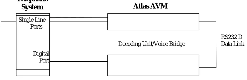
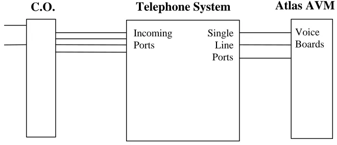
Telephone System Integration Definitions ... 8-1 Full Integration... 8-1 Partial Integration ... 8-1 Restricted Integration ... 8-2 Integration Types ... 8-2 Serial Integration ... 8-2 Serial Integration with Additional Equipment... 8-3 Possible Integration Features ... 8-4
Understanding the Integration Screens... 9-1 Parameters... 9-2 Voice Board Considerations ... 9-2 Accessing the Integration Screens ... 9-2 Global Parameters ... 9-2 The Edit Global Parameters Screen 1... 9-5 Telephone System Panel... 9-5 Dialogic Control Block Panel ... 9-5 The Serial Port /Integration Control Panels... 9-2 Port Parameters ... 9-17 Edit Port Telephone Parameters Screen 1 ... 9-17 The Sequences Panel ... 9-31 The Edit Port Telephone Parameters Screen 3 ... 9-33 Edit Port Telephone Parameters Screen 4 ... 9-34 The Edit Port Telephone Parameters Screen 5 ... 9-36 Edit Port Telephone Parameters Screen 6 ... 9-37 Edit Port Telephone Parameters Screen 7 ... 9-38
Chapter 10: Fax Installation
Configuring the Fax Board ... 10-1 Setting the I/O Port Addresses ... 10-1 Setting the AEB Signaling ... 10-2 Cabling the Fax and Voice Boards... 10-2 Installing the GammaFax Drivers ... 10-2 For Systems with More Fax Channels than Voice Board Ports10-3 Configuring the AUTOEXEC.BAT File ... 10-4
Chapter 11: System Administration Considerations
System Administration Steps ... 11-1Chapter 12: Final Cutover
Glossary
Figure 4-1: Using a Digit Grabber... 4-16
Figure 5-1: Erlang Table ... 5-4
Figure 6-1: Cord Connections for Dialogic Boards... 6-5 Figure 6-2: Rhetorex Telephone Connectors ... 6-6
Figure 7-1: Minimum Hardware Specifications... 7-2 Figure 7-2: Suggested Hardware Configuration... 7-2 Figure 7-3: Recommended Hard Drive Size ... 7-3
Figure 8-1: Example of Serial Integration ... 8-2 Figure 8-2: Serial Integration with a Voice Bridge ... 8-3 Figure 8-3: Example of In-Band Integration... 8-4
Overview of Installation and
Integration
About this Manual
The purpose of this manual is to guide you through the installation and integration of your Atlas AVM system. This manual is intended for use by certified Atlas AVM installers who are proficient in DOS, telephony, and voice processing.
The chapters in this manual are as follows:
• Chapter 1 gives a brief description of each chapter, provides a
summary of installation, and explains the conventions used in this manual.
• Chapter 2 is a quick guide to installation for experienced
installers.
• Chapter 3 describes evaluating the customer’s voice processing
needs and capabilities.
• Chapter 4 offers an overview of the Atlas AVM installation and
integration process.
• Chapter 5 tells how to plan the basic design of an Atlas AVM
system.
• Chapter 6 describes the functions of voice boards in your Atlas
AVM system and tells which models of the Dialogic and Rhetorex boards can be used.
• Chapter 7 gives general guidelines and recommendations for
building an Atlas AVM system.
• Chapter 8 gives suggestions for connecting Atlas AVM to your
telephone system.
• Chapter 9 tells how to program the Atlas AVM integration
screens.
• Chapter 10 explains how to add fax capability in your Atlas
• Chapter 11 covers the system administration issues that need to
be addressed as part of the installation process.
• Chapter 12 discusses the final steps required to make the system
operational.
• Glossary
• Index
Conventions
This manual uses the following conventions:
CONVENTION KEY INFORMATION
lowercase x indicates a variable in a file,
version, etc.
ALL CAPS indicates a file or directory
<italics> indicates a variable or place holder
Boxes➞Renumber example of a ‘path’ that a user can follow to get to a particular screen or field.
< > indicates a keyboard command
entry such as <Enter>
Lowercase bold used for commands or data to be typed at the keyboard
☞
Note: Information that is vital to thesuccess of a process
Tip: A shortcut or helpful hint
Caution: Possible damage to equipment
Evaluating the Customer
Before installing an Atlas AVM system, you need to gather information about the prospective customer. This will help you assess what that customer needs to build a voicemail system.
2. Decide which telephony features and applications the customer desires such as:
• Voicemail
• Auto attendant
• Audiotext
• AMIS-Analog Networking
• Fax
3. Determine whether the customer can or does meet the hardware and software requirements. (See Chapter 9, “Building the System.”) 4. Use the Customer Engineering Form in Chapter 3, “Evaluating the
Customer,” as you compile information about the customer.
Gathering Integration Information
In an Atlas AVM system, integration means enabling communication between Atlas AVM and a specific telephone system.
Telephone systems differ, and Atlas AVM must be programmed to communicate with the customer’s specific telephone system. To accomplish this you need to gather information about the customer’s telephone system.
1. Collect the telephone system information suggested on the Integration Form found in Chapter 4, “Integration Investigation.” This includes:
• Manufacturer, model, and software version
• Name of the person who maintains and services the telephone system
• Necessary hardware for voice messaging
• Information about telephone system operations
• Data packet information
Resources for doing this include the Atlas Telephone System
Compatibility Listing, the customer’s interconnect, the telephone
system manufacturer, and the telephone system documentation. 2. Gather any other needed information through on-site testing.
Designing the Basic System
Planning the Design
You will need to draw up a basic design from the information you have obtained from the customer. This will lay the groundwork for the system and help you determine sizing issues (see “Sizing the System” below). With the customer, you can help make decisions about how the overall system will work. The following steps will help you do this.
1. Design how the Auto Attendant will handle calls. This includes:
• Designing greetings which can be set for different times (business hours vs. non-business hours), days and ports
• Designing the options available for transferring from the Auto Attendant
2. Plan audiotext boxes in addition to the Auto Attendant. This includes:
• Determining the total number of audiotext boxes
• Planning audio menus
• Mapping the levels of audiotext boxes
3. Determine the number of voicemail, etc. boxes needed.
Sizing the System
After you have calculated the number of audiotext and voicemail boxes required for an Atlas AVM system, you also need to determine the number of voice board ports and the amount of disk storage required.
For worksheets and information regarding sizing, see Chapter 5, “Designing the Atlas AVM System.”
Building the System
Keep in mind the following as you build your Atlas AVM system: 1. Software requirements
• Atlas AVM installation disks
• DOS 5.0 or later, 6.2 recommended
• Fax Driver Disk (optional—available from Key System US)
• CO/Session 7.0 or later
☞
Note2. Hardware requirements
• Minimum hardware specifications (memory for CPU and ports)
• Suggested hardware configuration
• Recommended hard drive size
• Voice boards to handle number of ports required for the system
For information on system requirements, see Chapter 9, “Building the System.”
Installing Voice Boards
You need to consider the following:
1. Familiarize yourself with the voice boards Atlas AVM supports. You can help the customer decide which voice boards to buy based on the number of ports required, the number of available slots, and the cost of different boards.
2. Prior to installing voice boards, determine the following for your system (Atlas AVM will suggest defaults during Atlas AVM installation):
• I/O port address
• Hardware interrupt
• Base memory
3. Use the Rhetorex utility SHOWJUMP or the Dialogic voice board documentation to determine the jumper settings for the I/O port address before installing the voice boards. You can do this during or after installation of the Atlas AVM software.
4. Finally, physically connect the voice board(s) to the telephone system using a telephone line. Determine the correct jack connection for the voice board and make sure it matches the telephone jack connections on the wall.
For information on setting up and installing voice boards, see Chapters 6, 7, and 8.
Installing Atlas AVM
3. Install the voice board(s). 4. Attach the hardware lock. 5. Install the Atlas AVM disks.
6. Install and configure CO/Session (optional). 7. Create a VXNIGHT.BAT file (optional). 8. Reboot the system.
For information on installing the Atlas AVM software, see Chapter 10.
Connecting Atlas AVM to a Telephone System
Determine the type of integration desired and what will be needed to complete the connection.
For information on Connecting Atlas AVM to a Telephone System, see Chapter 11.
Integrating with the Telephone System
This process involves taking the information you have collected and inputting it into the Atlas AVM installation screens.
1. Refer to the Integration Form you filled out earlier as you program the Atlas AVM integration screens and parameters.
2. Plan to test the integration after you have completed “System Administration Procedures” below.
For instructions on programming the Atlas AVM integration screens, see Chapter 12.
Installing and Configuring Fax (Optional)
Fax capability is an add-on feature that must be purchased separately. Install and configure a GammaFax MLCP-4/AEB board, and install and configure the fax drivers provided by Key System US.
For more information, see Chapter 13, “Fax Installation.”
Now that Atlas AVM is installed and integrated with the telephone system, you need to instruct or assist the system administrator in the following areas:
1. Configuring system boxes—voicemail, audiotext, etc.
2. Recording the audio portion of company greetings and other audiotext boxes.
3. Testing the system.
• System design
• Integration with the telephone system
(For detailed administration information, see the Atlas AVM System
Administrator’s Manual.)
4. Training users on how to use the Atlas AVM telephone interface (can be done by the installer or the system administrator).
The Atlas AVM Pocket Reference Guide provides information on using the telephone interface. Atlas AVM also provides a tutorial over the telephone when box owners first set up their voicemail boxes.
Finalizing the Installation
Now that you have Atlas AVM installed, configured, and tested, you can take the final steps necessary to make the system operational. These steps, called the final cut over, include:
1. Connecting single line extensions to Atlas AVM. 2. Programming Atlas AVM lines at the telephone switch. 3. Organizing lines going to Atlas AVM into a hunt group. 4. Forwarding trunk calls (outside calls) to Atlas AVM. 5. Programming telephone handsets.
Quick Installation Guide
This chapter is an abbreviated version of Chapter 10, “Installing Atlas AVM.” For more detailed installation information, see Chapter 10.
What is Atlas AVM?
Atlas AVM is a DOS-based voice processing system that provides a suite of telephony features, as well as the means of integrating with a telephone switch.
Installation Procedure
Briefly, installing and setting up Atlas AVM involves the following: 1. Installing and setting up your voice boards.
2. Installing and configuring CO/Session to allow remote maintenance. 3. Installing the Atlas AVM disks and configuring your voice boards. 4. (optional) Creating a VXNIGHT.BAT file, a custom batch file Atlas
AVM runs daily at 4:00 AM.
5. Integrating with the specific telephone system, if necessary, through the Atlas AVM installation screens.
Installation Steps
Step 1: Equipment Inventory
Verify that you have all the needed equipment and software to complete a total installation of the Atlas AVM voice processing system:
• A computer equipped with the hardware listed in Step 2 below
• DOS (version 5.0 minimum, 6.2 or later preferred)
• Atlas AVM installation package:
- Installation disks - Hardware lock
- Atlas AVM System Administrator’s Manual - Atlas AVM Installer’s Manual
- Atlas AVM User Guide pamphlets (25 copies)
• Dialogic or Rhetorex voice board(s)
• Miscellaneous telephone equipment for connecting to the telephone system.
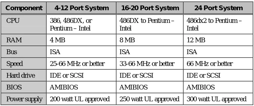
Step 2: Verify Hardware Requirements
Certain hardware specifications and configurations are required before a PC can be utilized for Atlas AVM voice processing.
Component 4-12 Port System 16-20 Port System 24 Port System
CPU 386, 486, or Pentium 486DX to Pentium 486DX4 to Pentium
RAM 4 MB 8 MB 12 MB
Bus ISA ISA ISA
Speed 25-66 MHz or higher 33-66 MHz or higher 66 MHz or higher
Hard drive IDE or SCSI IDE or SCSI IDE or SCSI
BIOS AMIBIOS AMIBIOS AMIBIOS
Power supply
200 watt UL approved 250 watt UL approved 300 watt UL approved
Figure 2 -1: Minimum Hardware Specifications
Step 3: Voice Board Setup and Installation
Step 4: Attach the Hardware Lock
Attach the hardware lock you received with your installation disks to LPT1.
Step 5: Have DOS running
You need DOS version 5.0 or later.
Step 6: Load the Atlas AVM Disks
In this step you will load the Atlas AVM software, load the voice board drivers, install QEMM, and configure your voice board.
The following disks are included in your Atlas AVM installation package:
Engine Disk 1 Engine Disk 2
Switch Integration Disk Rhetorex Driver Disk Dialogic Driver Disk 1 Dialogic Driver Disk 2 System Prompts Disk 1 System Prompts Disk 2 System Prompts Disk 3 QEMM Disk 1
QEMM Disk 2
Fax Driver Disk (if you have purchased the optional fax capability)
To begin installing, insert Engine Disk 1. Use a: install. Follow the prompts. For a complete guide to all the installation screens, see Chapter 10, “Installing Atlas AVM.”
Step 7: Create VXNIGHT.BAT (Optional)
Daily at 4:00 A.M. Atlas AVM offers the option of running a batch file of your own making. For Atlas AVM to run this file, it must be named VXNIGHT.BAT and must be located in the Atlas directory.
You can use your custom VXNIGHT.BAT file to perform automated tasks related to your Atlas AVM system. For example, the following would back up and then reboot/purge your Atlas AVM system:
Step 8: Install CO/Session
CO/Session allows remote maintenance of Atlas AVM, and also will allow Key System US technical support personnel to access your Atlas AVM system if you need assistance.
For more information, see Step 6, “Setting Up CO/Session,” in Chapter 10.
Step 9: Install Fax Capability (Optional)
You can purchase optional fax capability for your Atlas AVM system. For more information, see Chapter 13, “Fax Installation.”
Step 10: Reboot the System to Verify all Settings
Reboot your system and look for error messages.
Your Atlas AVM system is now running on system defaults. If your system is working with the default telephone system settings, refer to the
Atlas AVM System Administrator’s Manual for information on port setup
and programming system boxes (audiotext, voicemail, etc.). If your system is not working with the defaults, see Chapter12,
Evaluating the Customer
When you meet with customers who are interested in Atlas AVM, determine what their companies need to build a voicemail system. Evaluating customers’ situations and determining their needs will help you guide them in developing an Atlas AVM system. The final decisions should be based on considerations such as:
• Type of telephone system
• Telephony needs of the customer
• Cost of implementing everything required
Some customers may have telephone systems that do not have voicemail capability, especially if they have older, smaller systems. If that is the case, the customer will need to upgrade the telephone system in order to have voicemail. Atlas AVM requires only basic voicemail capabilities from the telephone system.
Gathering Information
Begin the evaluation process by collecting information about the prospective customer and recording it on a form such as the Customer Engineering Form given in this chapter. Use this as the basis for building a file on the customer.
The Customer Engineering Form
Company Information
Record the company name and address, the name of your contact person at the company, and also the person who will make the final decisions about purchasing an Atlas AVM system.
Site Information
Determine the approximate number of people who will be using voicemail and make an estimate of how many boxes this system will need. This will help you get a rough estimate of the size and cost of the Atlas AVM system.
Find out how many telephone lines there are from the central office to the company so you will know if additional lines will be required.
Telephone System Information
Collect information about the telephone system, including the
manufacturer, model number, and what software version is running. You may need to get some of this information from the company’s interconnect (telephone maintenance person).
Make a record of the name, address, and telephone number of the company’s interconnect. The interconnect’s knowledge about the telephone system can benefit you throughout the sales and installation process.
Telephony Applications/Features Desired
Customer Engineering Form
Company Information
1. Company name2. Company information Address
Phone Fax
3. Contact person Name
Phone 4. Final decision-maker Name Phone
Site Information
5. Number of employees who will use the Atlas AVM system 6. Estimated number of boxes
Voicemail boxes (boxes for voicemail users)
Auto Attendant boxes (boxes for company greetings) Audiotext boxes (boxes providing information)
Estimated total number of boxes 7. Number of lines from central office
Telephone system Information
8. Telephone system manufacturer9. Telephone system model
10. Telephone system software version 11. Interconnect company Name
Address
Telephone
Telephony Applications/ Features Desired
12. Voicemail
Yes / No
13. Auto Attendant
Yes / No
Integration Investigation
During the integration investigation, you will determine if Atlas AVM can be integrated with the customer’s telephone system and what voicemail features will be available.
Integration Requirements
Atlas AVM requires the following basic features from a telephone system in order to have voicemail:
• Necessary software version for voicemail
The telephone system software may need to be upgraded if it is not a voicemail capable version.
• Single-line extensions
The voice boards in Atlas AVM are analog boards and need single-line analog extensions. The user’s telephone does not need this type of extension, only the lines going into Atlas AVM.
• Ringing capability on the single-line extensions
The telephone system must have ringing capability because the voice boards and voice board drivers used in Atlas AVM require the use of ringing as their method of notification.
• End-to-end DTMF
The Atlas AVM system sends and receives address information for calls in the form of DTMF (Dual Tone Multi-Frequency) signals. The phrase ‘end to end’ refers to the ability of a device to both send and receive DTMF signals.
Investigation Steps
The information required to determine if successful integration is possible can be obtained from the telephone system’s documentation or
manufacturer, the customer’s interconnect vendor, or through on-site testing. (Some methods of on-site testing are covered in the Atlas
Certified Network Telephony Engineer Course Manual.)
As you gather the integration information listed in the following steps, enter the data in the corresponding sections of the Integration Form beginning on Page 4-7.
1. Document general information about the customer and the telephone system.
2. Find out if the telephone system software supports voicemail. You will probably need to consult the company’s telephone representative to find out what software version is installed on the telephone system, and what features this software has.
3. Find out if the telephone system has the necessary hardware for voicemail.
Locate single line extensions
If the customer has a fax machine or modem lines that go through the telephone system, those are single line extensions. Find out how many single lines there are.
If there are currently no single line extensions, you can add a single line card (SLC) to the telephone system. These are also called industry standard telephone cards (IST), or off-premise extension cards (OPX).
Check for ringing on single line extensions
Dial a single line extension from another single line extension to see if you hear ringing over the telephone.
The voice boards and their drivers used in Atlas AVM necessitate the use of ringing as the method of notification. Therefore, the telephone system has to have ringing capability on the extensions going to Atlas AVM.
If the telephone system does not currently have ringing capability, you can add a ‘ring generator’ card.
Check for end-to-end DTMF • Attendant console
• Single line handset
The voice boards in the Atlas AVM machine, being analog devices, necessitate the use of DTMF as the method of receiving control information.
If the telephone system cannot provide DTMF on the extensions going to Atlas AVM, then an additional DTMF generator board must be added to the telephone system.
4. Find out how the telephone system operates concerning the following:
• hunt groups
• disconnects
• supervised transfers
• event signaling
• off-premise transfers
5. Make a list of equipment or software that needs to be upgraded. 6. Obtain information about the data packets that are sent by the
telephone system.
You can gather this information from the customer’s interconnect or from the telephone system vendor. If you cannot collect this information through these avenues, or you want to confirm the information you have collected, you will need to use a digit grabber. For an example of how to use a digit grabber, see Page 4-16.
You will enter the data packet information you have gathered when you are ready to program the Atlas AVM integration screens covered inChapter 12, “Integrating With the Telephone System.” You do not need to input every data packet into Atlas AVM— only the ones that will be relevant for Atlas AVM operations. These would include such packets as ‘forward, busy,’ ‘forward, no answer,’ ‘retrieve message,’ and possibly a ‘disconnect.’
Read the information in the next section, “Understanding Data Packets,” before you fill out the data packet portion of the Integration Form.
Understanding Data Packets
The data packet investigation involves the following three parts:
• Events and Packet Identifiers
• Packet Formats
Events and Data Packet Identifiers
You must learn the ‘events’ the telephone system sends data packets on and their corresponding ‘packet identifiers’ (i.e. the code used to denote that event).
Example:
Event Packet Identifier Forward, busy 2 Forward, no answer 3 Retrieve message 4 Disconnect 7
Data Packet Formats
You must learn the packet format of the data packets. This involves knowing what part of the data stream pertains to such things as the packet identifier, the called party extension, the calling party extension, and possibly other information.
Example:
The telephone system could send a string of digits to Atlas AVM that communicates the called party extension and the packet identifier:
1332
Atlas AVM must know what the packet format is in order to understand this communication. Since there is no standard default packet format, Atlas AVM does not know whether the packet identifier is ‘1’ and the called party extension is ‘332,’ or if the called party extension is ‘133’ and the packet identifier is ‘2.’ However, if we tell Atlas AVM what positions in the data packet relate to what information, then Atlas AVM can understand this data packet.
☞
NoteIf the called party was ‘133,’ and the packet identifier was ‘2’ (for example, a forward busy), then the packet format would be:
Data Packet: 1 3 3 2
Positions: 0 1 2 3 4 5 6 7 8 9
Packet Identifier: 2 Packet Identifier Offset (position) 3
Packet identifier Length: 1
Called Party Offset (position): 0 Called Party Length: 3
Atlas AVM Definition of a Data Packet
For every data packet that you input into Atlas AVM, you must tell Atlas AVM how it should ‘define’ that packet. The following section contains the current possible data packet definitions and how Atlas AVM acts for each definition.
Atlas AVM Data Packet Definitions
Direct to Box
The call goes directly to a box owner’s mailbox, without ringing the extension, based on the ‘called party’ information. Atlas AVM plays the box owner’s personal greeting without any additional prompts.
Forwarded
Atlas AVM plays the following prompt:
“<Name of box owner> is not available to take your call.” Atlas AVM then sends this call to the box number of the ‘called party’ and carries out whatever is in the Busy Option field (e.g., Take Message, Alternate Extension, Caller Options).
Atlas AVM plays the following prompt: “I’m sorry, that extension is busy.”
Forwarded No Answer
Atlas AVM plays the following prompt:
“I’m sorry, that extension does not answer.”
Atlas AVM then sends this call to the box number of the ‘called party’ and carries out whatever is in the No Answer Option field (e.g., Take Message, Alternate Extension, Caller Options).
Retrieve Message
Atlas AVM recognizes the caller as a box owner, sends the call to a box based on the ‘called party’ information, and then asks for the passcode for that box.
Trunk
Atlas AVM recognizes the call as being a ‘trunk’ call. This means that the Trunk Port field on the Integration Data Packet Parameters screen is valid. Atlas AVM plays the port greeting or Auto Attendant for outside calls that are identified as the trunk listed in the Trunk Port field.
The Integration Form
The Integration Form, found on the next page, can be used by the Atlas AVM installer to help determine if a telephone switch can be integrated with, and to document the details of that integration.
If the particular telephone system in question is listed in the Atlas
Telephone System Compatibility Integration Listings, use this form just
Integration Form
1. General Information
(This information can be obtained from the Customer Engineering Form in Chapter 3.)
a. Customer
b. Contact
c. Telephone system manufacturer
d. Telephone system model
e. Software version
2. Telephone System Software Version
Is there a particular telephone system software version that is needed for voicemail?
a. If Yes, what is that version?
Compare 2a. with 1e. If 1e. is the same or a higher version (check with the manufacturer to make sure), then continue on with this form.
If 1e. is a lower version, then the telephone system software must be upgraded. Make note of this on the Telephone system Upgrade Form.
3. Necessary Hardware for Voice Messaging
Does the telephone system have the necessary hardware for voice messaging? This entails the following items:
a. Available single-line extensions Yes / No
If Yes, how many?
b. Ringing on the single line extensions that will be used by Atlas AVM Yes / No c. DTMF tones on the single line extensions that will be used by Atlas AVM
1. From an attendant console Yes / No
2. From a 2500 set Yes / No
4. Telephone system Operations
a. Does this telephone system allow for hunt groups? If Yes:
Yes / No
When all single line extensions in a hunt group are busy, what happens to the next:
Trunk caller (outside caller): Station caller (inside caller):
b. If hunt groups are not available, can all lines be chained to forward to the next available line and eventually back to a live attendant?
c. How does the telephone system provide notification of a disconnect to a single line extension?
Dial tone (IST port): Data packet (IST port programmed as VM):
Reorder:
Loop current drop:
d. Does the telephone system allow supervised transfers? (This is only relevant if there are no data packets.)
e. What type of signaling, from a single line extension, does the telephone system need for the following events?
1. Call transfer
2. Recall busy (supervised transfer only) 3. Recall no answer (supervised transfer only) 4. Call connected (supervised transfer only) 5. Message waiting light on
6. Message waiting light off
7. Call screening park (screened calls only)
8. Call screening remove park (screened calls only)
5. Telephone system Upgrade Form
List the telephone system equipment or software that needs to be upgraded in order to accomplish voice messaging.
1. 2. 3. 4. 5.
6. Data Packet Events and Formats
As you fill out the data packet forms, it is recommended that you first complete the second column for all relevant telephony scenarios based upon the information you learn through using a digit grabber. Then go back and complete the additional relevant information in the other columns. The first scenario is an example of a data packet that a telephone system might send for a forward, busy call.
Telephony Scenario
Packet Identifier (Event Code)
Packet Format Packet Definition (Atlas AVM Definition)
EXAMPLE Packet example: 1 3 3 2
1. Forward, Busy: Packet example: 1 3 3 2 Positions: 0 1 2 3 4 5 6 7 8 9 (Choose only one)
Retrieve msg.: ___
Identifier: x x x 2 Packet identifier: 2 (ASCII) Forwarded: ___
(Event code) Packet ident. offset: 3 Forward, busy: ___
Packet ident. length: 1 Fwd, no answer: ___
x = Called Party Direct to Box: ___
y = Calling Party Called party ext. offset: 0 Trunk: ___
Called party ext. length: 3 Terminate call: ___
Ignore: ___
Calling Party ext. offset: _____ DTMF: ___
Calling party ext. length: _____ Etc.
Telephone Scenarios
The following are scenarios that you should create to identify the data packets that are sent by the telephone system.
Forwarded Busy
A station is programmed to call forward on a busy state to AVM.
Forwarded No Answer
A station is programmed to call forward on a no answer state to AVM.
Forward All Calls
A station is programmed to call forward all calls to AVM.
Retrieve Message
A station calls or reaches AVM to retrieve messages. Four different methods could accomplish a station call to AVM to retrieve messages with an accompanying data packet.
1. Call the voicemail hunt group. 2. Call the analog extension.
3. Press a message waiting indicator button.
4. Call yourself when your station is programmed to call forward to AVM.
Trunk Call
Incoming CO/trunk call is routed to AVM to be answered.
Voicemail Transferred Recall
AVM transfers a caller to a station that is not programmed to call forward. A busy or no answer state on that station, the telephone system will recall (send back) to the originating transferring extension (AVM).
☞
NoteTelephony Scenario
Packet Identifier
(Event Code)
Packet Format Packet Definition
(AVM Definition)
Packet: _______________
1. Forward, Packet: ______________ Positions: 0 1 2 3 4 5 6 7 8 9 (Choose only one)
Busy: Direct to Box: ___
Identifier: ____________ Packet identifier: ______ Forwarded: ___
(Event code) Packet ident. offset: ______ Forward, busy: ___
Packet ident. length: ______ Fwd, no answer: ___
x = Called Party Retrieve msg: ___
y = Calling Party Called party ext. offset: ______ Trunk: ___
Called party ext. length: ______
Calling party ext. offset: ______
Calling party ext. length: ______
Trunk Port: ______
Telephony Scenario
Packet Identifier (Event Code)
Packet Format Packet Definition (AVM Definition)
Packet: ________________
2. Forward, Packet: ________________ Positions: 0 1 2 3 4 5 6 7 8 9 (Choose only one)
No answer Direct to Box: ___
Identifier: ______________ Packet identifier: ______ Forwarded: ___
(Event code) Packet ident. offset: ______ Forward, busy: ___
Packet ident. length: ______ Fwd, no answer: ___
x = Called Party Retrieve msg: ___
y = Calling Party Called party ext. offset: ______ Trunk: ___
Called party ext. length: ______
Calling party ext. offset: ______
Calling party ext. length: ______
Telephony Scenario
Packet Identifier
(Event Code)
Packet Format Packet Definition
(AVM Definition)
Packet: _______________
3. Retrieve Packet: _______________ Positions: 0 1 2 3 4 5 6 7 8 9 (Choose only one)
Message: Direct to Box: ___
Identifier: ______________ Packet identifier: ______ Forwarded: ___
(Event code) Packet ident. offset: ______ Forward, busy: ___
Packet ident. length: ______ Fwd, no answer: ___
x = Called Party Retrieve msg: ___
y = Calling Party Called party ext. offset: ______ Trunk: ___
Called party ext. length: ______
Calling party ext. offset: ______
Calling party ext. length: ______
Trunk Port: ______
Telephony Scenario
Packet Identifier (Event Code)
Packet Format Packet Definition (AVM Definition)
Packet: _______________
4. Trunk Call: Packet: _______________ Positions: 0 1 2 3 4 5 6 7 8 9 (Choose only one)
Direct to Box: ___
Identifier: ______________ Packet identifier: ______ Forwarded: ___
(Event code) Packet ident. offset: ______ Forward, busy: ___
Packet ident. length: ______ Fwd, no answer: ___
x = Called Party Retrieve msg: ___
y = Calling Party Called party ext. offset: ______ Trunk: ___
Called party ext. length: ______
Calling party ext. offset: ______
Calling party ext. length: ______
Telephony Scenario
Packet Identifier
(Event Code)
Packet Format Packet Definition
(AVM Definition)
Packet: _______________
5. Forwarded all calls:
Packet: _______________ Positions: 0 1 2 3 4 5 6 7 8 9 (Choose only one)
Direct to Box: ___
Identifier: _____________ Packet identifier: ______ Forwarded: ___
(Event code) Packet ident. offset: ______ Forward, busy: ___
Packet ident. length: ______ Fwd, no answer: ___
x = Called Party Retrieve msg: ___
y = Calling Party Called party ext. offset: ______ Trunk: ___
Called party ext. length: ______
Calling party ext. offset: ______
Calling party ext. length: ______
Trunk Port: ______
Telephony Scenario
Packet Identifier (Event Code)
Packet Format Packet Definition (AVM Definition)
Packet: _______________
6. Voicemail transferred recall:
Packet: _______________ Positions: 0 1 2 3 4 5 6 7 8 9 (Choose only one)
Direct to Box: ___
Identifier: _____________ Packet identifier: ______ Forwarded: ___
(Event code) Packet ident. offset: ______ Forward, busy: ___
Packet ident. length: ______ Fwd, no answer: ___
x = Called Party Retrieve msg: ___
y = Calling Party Called party ext. offset: ______ Trunk: ___
Called party ext. length: ______
Calling party ext. offset: ______
Calling party ext. length: ______
Telephony Scenario
Packet Identifier
(Event Code)
Packet Format Packet Definition
(AVM Definition)
Packet: _______________
7. (Other): Packet: _______________ Positions: 0 1 2 3 4 5 6 7 8 9 (Choose only one)
Direct to Box: ___
Identifier: _____________ Packet identifier: ______ Forwarded: ___
(Event code) Packet ident. offset: ______ Forward, busy: ___
Packet ident. length: ______ Fwd, no answer: ___
x = Called Party Retrieve msg: ___
y = Calling Party Called party ext. offset: ______ Trunk: ___
Called party ext. length: ______
Calling party ext. offset: ______
Calling party ext. length: ______
Trunk Port: ______
The following packets are called ‘in-band supervisory’ packets. They do not have called party or calling party information. They are packets the telephone system uses to denote certain telephony situation. Enter the sequences that AVM recognizes for disconnect and off-hook. The AVM menu path tells how to get to the AVM screen where you need to enter this information.
7. Disconnect
Disconnect Sequence
AVM Menu Path
__________ System Installation Options
Port Telephone System
Select Port
Select Port Telephone System
Port Telephone Parameter Options
General Parameters
8.
Off-hook Sequence
AVM Menu Path
__________ System Installation Options
Port Telephone System
Select Port
Select Port Telephone System
Port Telephone Parameter Options
General
Field = Outbound Dial Tone Digit
Data Packet Timeout and Termination
Is there a data packet timeout? Yes / No If ‘Yes,’ what is it? _______
Data packet timeout is the length of time AVM will wait after going off hook to receive a data packet. The timeout should be as short as possible. Any DTMF received will be assumed to be a data packet from the telephone system.
Is there any ‘character’ that the
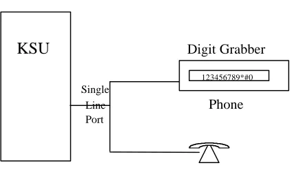
Using a Digit Grabber
You can use a Digit Grabber to manually gather data packets.
Equipment Needed
Quantity Item
1 Single line extension programmed for voicemail (sends data packets)
1 Line splitter (this will allow us to connect two devices, 2500 handset and the digit grabber, to the same extension thereby allowing us to view the data packets sent to this extension)
2 Line cords (for the connection from the 2500 handset and digit grabber to the line splitter)
1 2500 handset (this will take the role of a Atlas AVM machine)
1 Digit grabber (this will display the digits, sent via DTMF, that comprise the data packets sent to the extension the digit grabber is connected to via the line splitter)
2 Digital handset programmed to ‘call forward on busy’ to the extension that our 2500 handset is at (these handsets will be used to place calls to each other in order for the telephone system to generate data packets)
KSU
Digit Grabber123456789*#0
Single
Line
Phone
Port
Digit Grabber Set-up Procedure
1. Pick a single line extension (NOTE: This extension must be
programmed for data packets/in-band signaling). Connect a cable from that extension’s wall jack to the line splitter.
2. Connect the digit grabber to the line splitter with either a cable or directly.
3. Connect the 2500 handset to the line splitter. 4. Turn on the digit grabber.
Test Procedure
1. Test 2500 handset and digit grabber: At 2500 handset, dial an extension.
You should see the digits dialed on the digit grabber. (RESET)
Data Packet Collection
1. Decide which extensions to use for each instrument.
Instrument Ext.
Digital handset ‘A’ − call forward to Atlas AVM (made to be busy; no answer; etc.) Digital handset ‘B’ − instrument that calls handset ‘A’ Digit grabber
2. To learn of a ‘forward busy’ event:
3. Program digital handset ‘A’ to call forward to the extension that the digit grabber is attached to (the pseudo Atlas AVM machine).Take digital handset ‘A’ off-hook and create a busy (press intercom). 4. At digital handset ‘B’ dial digital handset ‘A.’ The telephone system
will attempt to connect this call to handset ‘A’ but will not be able to because of the busy state. Because handset ‘A’ is programmed to ‘forward calls on busy’ to the extension that is our 2500 handset (Atlas AVM), the telephone system will then forward the call to that extension. When the telephone system does the transfer of the call it will also send along a data packet.
7. To learn of the other events do the same basic procedure except recreate the other telephony scenarios (e.g., no answer, disconnect, CO line call, retrieve message, Atlas AVM initiating a call, etc.).
8. Document what you learn on the Integration Form.
☞
NoteDesigning the Atlas AVM System
After you have determined that you can integrate with the customer’s telephone system, you should work with a company representative to draw up a basic design for the Atlas AVM system. This will help you in several areas:
• Finding out what type of system the customer wants so you can begin to put it together.
• Closing the sale. Giving the customer a more complete picture of what Atlas AVM can do for them helps to secure the sale.
• Determining the Atlas AVM system size required by the company. You made an estimate of how many boxes this company will need in the evaluation phase. Now you need to come up with a more accurate count.
Planning the Basic Design
Considerations for designing a system are outlined below.
1. Design how the Auto Attendant will handle calls. This includes:
Primary or Secondary Auto Attendant—The Auto Attendant answers all incoming calls, or a live operator answers calls except when all calls cannot be accommodated by the operator. Greetings—which can be set for different times (e.g. business hours vs. non-business hours), days, or ports.
Caller Options—which give callers options for transferring from the Auto Attendant box to an extension, the operator, or another audiotext box. Callers also hear caller options when they enter an invalid digit or fail to respond to a voice prompt.
2. Planning audiotext boxes. This includes the following:
Planning audio menus—which are the transfer options callers hear in audiotext boxes.
3. Find out what the customers want their greeting and other audiotext boxes to look like.
Help the customers determine what they want their system to sound like.
Create some rough scripts based on the customer’s responses.
4. Planning individual voicemail boxes. This includes:
Obtaining a list of extension numbers of the people who will be using the Atlas AVM system.
Deciding which range of Atlas AVM boxes to use for voicemail boxes.
Renumbering the Atlas AVM boxes to match the extension numbers of their owners.
After you have mapped out the basic design of the system, you should know approximately how many total boxes are required for the Atlas AVM system.
Sizing the System
The size of the Atlas AVM system purchased is based on the number of boxes the company needs. Atlas AVM systems are available in the following box group sizes:
50, 300, 500, 750, 1000, 2500, 5000, 7500, 10,000
Calculate the number of boxes based on the basic design of the system, allowing for modifications or growth.
You also need to determine the number of ports and the disk space required for the system. Use the Erlang Table and the following worksheets:
• Auto Attendant
• Audiotext Calls
• Voicemail
• Ports Required
• Voice Storage
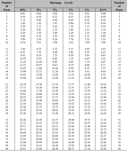
Erlang Measurement
Erlang is a unit of measurement for telephone traffic. (Total call seconds per hour divided by 3600 equals an Erlang.) The Erlang measurement is used to ensure that Atlas AVM is sized large enough to minimize the number of blocked calls (busy signals) during the peak hours of calls. Because all calls that come into a system are not evenly dispersed, you cannot merely estimate the number of call seconds and then plug that number into a chart. The Erlang measurement accounts for calls that are concentrated in the same time period (i.e. overlap).
Number of
Blockage Levels Number of Ports 10% 5% 3% 2% 1% 0.1% Ports
1 0.01 0.05 0.02 0.01 0.01 0.00 1
2 0.54 0.36 0.22 0.15 0.10 0.10 2
3 1.14 0.85 0.59 0.45 0.35 0.19 3
4 1.84 1.45 1.07 0.86 0.70 0.44 4
5 2.59 2.11 1.62 1.35 1.13 0.76 5
6 3.38 2.81 2.23 1.89 1.61 1.14 6
7 4.20 3.55 2.88 2.48 2.15 1.58 7
8 5.04 4.32 3.55 3.10 2.72 2.05 8
9 5.89 5.10 4.26 3.74 3.32 2.55 9
10 6.76 5.91 4.98 4.42 3.94 3.09 10
11 7.64 6.72 5.72 5.11 4.59 3.65 11
12 8.53 7.55 6.48 5.82 5.25 4.23 12
13 9.42 8.39 7.25 6.54 5.93 4.83 13
14 10.33 9.24 8.04 7.28 6.63 5.44 14
15 11.24 10.10 8.83 8.03 7.34 6.07 15
16 12.15 10.97 9.63 8.79 8.06 6.71 16
17 13.07 11.84 10.44 9.56 8.79 7.37 17
18 13.99 12.72 11.26 10.33 9.53 8.04 18
19 14.92 13.60 12.09 11.12 10.28 8.72 19
20 15.86 14.49 12.92 11.91 11.04 9.40 20
21 16.79 15.38 13.76 12.71 11.80 10.10 21
22 17.72 16.28 14.60 13.51 12.57 10.80 22
23 18.66 17.18 15.45 14.32 13.35 11.51 23
24 19.61 18.08 16.30 15.14 14.13 12.23 24
25 20.55 18.99 17.15 15.96 14.92 12.96 25
26 21.50 19.90 18.02 16.79 15.72 13.69 26
27 22.45 20.81 18.88 17.62 16.52 14.42 27
28 23.40 21.72 19.75 18.45 17.32 15.17 28
29 24.35 22.64 20.62 19.29 18.13 15.91 29
30 25.30 23.56 21.49 20.13 18.94 16.67 30
31 26.26 24.48 22.37 20.98 19.75 17.42 31
32 27.21 25.41 23.25 21.83 20.57 18.19 32
33 28.17 26.33 24.13 22.68 21.40 18.95 33
34 29.13 27.26 25.02 23.54 22.22 19.72 34
35 30.09 28.19 25.91 24.39 23.05 20.50 35
36 31.05 29.12 26.80 25.25 23.89 21.27 36
37 32.02 30.06 27.69 26.12 24.72 22.06 37
38 32.98 30.99 28.58 26.98 25.56 22.84 38
39 33.94 31.93 29.48 27.85 26.40 23.63 39
40 34.91 32.86 30.38 28.72 27.24 24.42 40
Auto Attendant
AA = Auto Attendant
VR = Voice Response (calls coming back to the Auto Attendant)
1. ______ Number of calls to the Auto Attendant during peak hours 2. x ______ Length of prompts for AA (in seconds)
3. = ______ AA seconds per hour
4. ______ VR calls
5. x ______ Average VR time (in seconds)
6. = ______ VR seconds per hour
7. ______ AA seconds per hour (from line 3) 8. + ______ VR seconds per hour (from line 6)
9. = ______ Total call seconds per hour for the Auto Attendant (AA + VR)
Audiotext Calls
10. ______ Number of audiotext calls per peak hour 11. x ______ Number of boxes listened to during a call 12. = ______ Number of calls and boxes
13. x ______ Length of average audiotext message (in seconds)
Voicemail
Message Calls (leaving a message)
15. ______ Number of employees
16. x ______ Number of messages per day per employee
17. = ______ Total message calls per day
18. x ______ Length of entire message sequence (in seconds) (prompts + messages + editing)
19. = ______ Total message call seconds per day
20. /8 ______ Hours in business day
21. = ______ Message call seconds per hour
Subscriber Calls (listening to messages)
22. ______ Number of employees
23. x ______ Number of calls per day to check messages 24. = ______ Total subscriber calls per day
25. x ______ Length (seconds) of a subscriber call 26. = ______ Total subscriber call seconds per day
27. /8 ______ Hours in business day
28. = ______ Subscriber call seconds per hour
Ports Required
Step 1: Add the following lines from the previous worksheets
Line 14, Audiotext ______ Line 21, Message calls
Line 28, Subscriber calls
______ ______
Total ______
Step 2: Take the total from Step 1 and divide it by 3600 to determine the Erlang number. Go to the Erlang Table and find the line closest to that number in the 2% to 3% blockage range. Find the number of ports
associated with that line and enter it here. ______
Total Ports Needed
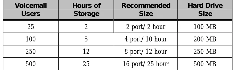
______Voice Storage
1 hour of voice storage = 10 MB of disk storage
Voicemail
1. ______ Numbers of employees
2. x ______ Number of messages left per employee per day 3. = ______ Total messages per day
4. x ______ Length (seconds) of messages left by callers
5. = ______ Total seconds of voicemail storage per day
Audiotext
6. ______ Length (seconds) of average audiotext message 7. x ______ Number of audiotext boxes
Voice Storage Required
Step 1: Add the following lines from the Voice Storage worksheet:
Line 5, Voicemail ______ Line 6, Audiotext ______
Total = ______
Step 2: Divide the total from Step 1 by 60 (i.e. minutes divided by seconds)
÷ 60
Total = ______
Step 3: Divide the total from Step 2 by 60 (i.e. hours divided by minutes)
÷ 60
Total = ______
Step 4: If 1 hour of voice storage = 10 MB of disk storage Then ____ hours of voice storage (Step 3) = Plus 10 MB for the Atlas AVM files =
______ MB of disk storage + 10 MB for Atlas AVM
Installing Voice Boards
Understanding Voice Boards
Voice boards perform the following functions:
• Digit Processing: detecting and generating DTMF tones
• Voice Processing: playing and recording messages
• Call Processing: listening for and characterizing tones and frequencies, and reporting them back to Atlas AVM Atlas AVM can use certain voice boards manufactured by Dialogic and Rhetorex. These boards and their setup are described in sections of this chapter and in Chapters 7 and 8. Read the material that applies to the voice boards used in your system.
Voice Board Installation
Unpacking and Handling the Boards
Before you unpack your voice boards, make sure you have a clear, clean, dust-free space to work.
Printed circuit boards can be damaged easily if subjected to rough
handling or electrostatic conditions. Wear an anti-static wrist strap and use electrostatic-dissipative mats whenever you handle PC boards.
Installing the Voice Boards
See Chapters 7 and 8 for setup and strapping options for your voice boards.
When all boards have been prepared, follow the instructions below to install them in the PC:
2. Remove the PC cover and set it aside, along with the screws, in a safe place.
3. Remove the first voice board from its anti-static bag. Set the jumpers according to the information in Chapters 7 or 8.
4. Slide the board into the slot farthest from the power supply, seating it firmly in the connector strips.
5. Tighten the screw connecting the board to the chassis. (This grounds the board.)
6. Remove the second board (if any) from its anti-static bag and install it in the slot next to the number one board. Repeat for all remaining boards.
7. When all boards have been installed in their proper slots, return the cover to the PC and attach it securely.
8. Reattach all power cords and power up the PC and any peripheral equipment.
Attaching the Cables
To attach the voice boards to the telephone system, follow the instructions below.
Insert a plug into the jack in the rear bracket of the voice board. There is a snap or click when the plug is properly connected.
Continue to connect the RJ-11 or RJ-14 plugs to all the voice boards.
☞
Note
If you are installing a one-board system it is recommended that you install the voice board in the slot that is farthest away from the power supply. If there is more then one board in your system, install the number one board in the slot farthest from the power supply, the number two board in the slot next to the number one board, and so on.
☞
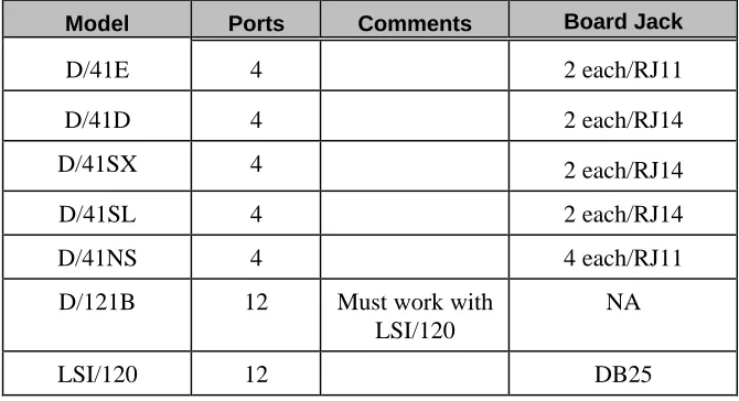
NoteDialogic Voice Boards
The Dialogic voice boards that you can use with your Atlas AVM system include those shown in Table 6 -1.
Model Ports Comments Board Jack
D/41E 4 2 each/RJ11 D/41D 4 2 each/RJ14 D/41SX 4 2 each/RJ14 D/41SL 4 2 each/RJ14 D/41NS 4 4 each/RJ11 D/121B 12 Must work with
LSI/120
NA
LSI/120 12 DB25
Table 6 -1: Dialogic Board Specifications
D/41E
A 4 port digital store-and-forward voice board with world approvability, access to resource modules, and additional power for future firmware features.
D/41D
A 4 port digital board used to connect to single line station ports from a PBX or telephone company. Typical 2500 telephone interface, i.e. Centrex/SMDI, loop station interface.
D/41SX
A 4 port digital board used with the Mitel PBX using COV or Super Set integration.
D/41SL
A 4 port digital board used with the Northern Telecom SL-1 PBX using SL-1 station integration.
D/41INS
D/121B-LSI/120
Used together to give 12 ports – same as the D/41D but supports 12 analog ports.
Basic Analog Configuration
The D/41D board contains everything needed for the basic 4-port analog configuration. Higher density 8-port and 12-port boards use a SpringBoard connected via PEB cable to an LSI board.
The basic 12-port analog application uses a D/121B board connected via a PEB cable to one LSI/120 board. This configuration will handle up to 12 telephone lines. A PEB terminator must be installed on both the voice board and the LSI/120.
Multiple Board Configurations
Dialogic Telephone Connectors
T2 T1 R1 R2
RJ14
D/41D
RJ14 RJ14 T RRJ-11
D/41NS
RJ11 RJ11 RJ11 RJ11D121/LSI/120
DB25 1 2 3 4 5 6 7 8 9 10 11 12 T1 R1 T2 R2 T3 R3 T4 R4 T5 R5 T6 R6 13 14 15 16 17 18 19 20 21 22 23 24 25 T7 R7 T8 R8 T9 R9 T10 R10 T11 R11 T12 R12Pin Term. Pin Term.
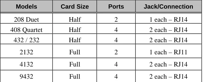
Rhetorex Voice Boards
The Rhetorex voice boards that you can use with your Atlas AVM system include those shown in the following table.
Models Card Size Ports Jack/Connection
208 Duet Half 2 1 each – RJ14 408 Quartet Half 4 2 each – RJ14 432 / 232 Half 4 2 each – RJ14 2132 Full 2 1 each – RJ11 4132 Full 4 2 each – RJ14 9432 Full 4 2 each – RJ14
Table 6 -2: Rhetorex Board Specifications
Rhetorex Telephone Connectors
T2 T1 R1 R2 RJ14
RJ14
15 Pin D SUB
432/2132/4132/9432
Figure 6 -2: Rhetorex Telephone Connectors
RDSP/432
A 4 port, analog, half length board that supports 4 analog telephone interface ports.
RDSP/208
RDSP/408
A 4 port, analog, half length card. This board supports 4 analog single line telephone interface ports. Only one board allowed per system.
RDSP/2132
A 2 port, analog board that supports 2 analog telephone interface ports.
RDSP/4132
A 4 port analog board that supports 4 analog telephone interface ports.
RDSP/9432
A 4 port analog board that is internationally approved. It supports 4 analog telephone interface ports.
Call Progress Tones
Your telephone system uses audible tones to indicate the progress of a call. These call progression tones include four basic tones:
• dial tones
• busy tones
• ring tones
• reorder tones
Dial tone: This tone tells the caller that the central office or the telephone
system is ready to receive address signals (i.e. telephone number or extension).
Busy tone: This tone indicates that the number being called is busy.
Ring tone: When a caller places a call, a ring tone is returned to the caller.
This ring tone, also called a ring back, indicates that a path has been established and the called instrument is being rung.
Reorder tone: The tone that sounds when a telephone has been left off
hook longer than the maximum length of time.
By listening to the call progression tones, a caller can recognize the state of a call. Similarly, the voice board can listen to call progression tones and recognize the state of a call. However, there is no standard way for a telephone system to express these tones. Consequently, the specific tone characteristics used by the telephone system must be defined in order for the voice board and driver to integrate with the telephone system.
☞
NoteTone Characteristics
Tone characteristics relate to three main areas:
Frequency: The number of vibrations, or oscillations, per time unit of an
alternating current.
Duration: The complete signal sequence consisting of ‘on time’ (the
signal) and ‘off time’ (silence).
Cadence: The length of the ‘on time’ and the length of the ‘off time’ in a
one tone cycle.
These three tone characteristics (frequency, duration, cadence) must be determined for each of the four call progress tones (dial tone, busy tone, ring tone, and reorder).
The driver can recognize a tone if the tone’s characteristics match the parameters for a tone in the tone table.
Utility programs such as Call Analysis for Dialogic or AccuCall Plus for Rhetorex, allows users to determine, test and define the frequency, duration and cadence elements of the environment’s call progression tones.
Supervised Transfers
If the telephone system does not provide in-band signaling (i.e., data packets), then Atlas AVM will have to supervise all its transfers in order to ascertain the result of those transfers (e.g., busy, no answer, etc.). This is called a ‘supervised’ transfer. Atlas AVM must therefore be able to accurately understand the tones the telephone system uses to denote these different events, which are called ‘call progress tones.’ This is done by building a database file of the characteristics of a particular telephone system’s call progress tones.
The following is an example of a supervised call:
1. An outside call comes into a PBX. The PBX is programmed to send
all calls to Atlas AVM.
2. Atlas AVM plays the port greeting for the caller and prompts the caller to enter the desired extension.
3. The caller enters the number 100.
4. Atlas AVM looks in its voicemail box configuration database for box 100. It transfers the call to extension 100.
system to transfer the call to extension 100. (At this point the outside caller is ‘parked’ at the telephone system.)
6. Since this telephone system does not use in-band signaling (i.e., no data packets), Atlas AVM is going to ‘stay on the line’ during the transfer in order to learn the result of this transfer.
7. In this case, extension 100 is busy. The telephone system sends a particular tone to denote a busy event.
8.
Atlas AVM, which is still ‘listening on the line,’ references its tone table to see what this tone denotes.
9. Once Atlas AVM realizes that extension 100 is busy, it looks in its voicemail box configuration database for what to do when extension 100 is busy−in this case, take a message.
10. Atlas AVM then connects back to the parked call and plays the user’s box greeting for voicemail box 100. The caller can then leave a voicemail message.
For step 8 to work, a tone table must be created for this particular telephone system. One way to do this with a Rhetorex voice board is to use the program AccuCall Plus.
AccuCall Plus (Rhetorex only)
AccuCall Plus is a program developed by the vendor Rhetorex. This program can be used with a Rhetorex voice board to analyze the tone characteristics of a particular telephone system.
In this regard, it is like a protocol analyzer in the data communication field, except that AccuCall Plus analyzes tone characteristics.
AccuCall Plus can analyze the tone characteristics for each of the call progress events (e.g., dial tone, busy tone, ring tone). AccuCall Plus then puts the information on the specific tone characteristics into a tone table (i.e., a database file). This tone table can then be referenced by the Rhetorex driver and Atlas AVM.
Installation and Use of AccuCall Plus
AccuCall Plus is a DOS executable program. It must be run on the PC that will have the Rhetorex voice board in it. Follow the steps below to run AccuCall.
Copy files (from AccuCall Plus disk).
1. MD c:\rhetorex
2. COPY a:\*.* c:\rhetorex