Conference Chair:Prof.Dr.G.Manoj Someswar, Director General, Global Research Academy,
Design & Development of a Novel Remote Data Integrity
Checking Model for Improved Efficiency and Security
Ganji Naveen Kumar
1, B.Sai Maogna
2, Prof.Dr.G.Manoj Someswar
31.
M.Tech.(CSE) from Narasimha Reddy Engineering College, Affiliated to JNTUH,
Hyderabad, Telangana, India
2.
M.Tech. (CSE), Assistant Professor, Department of CSE, Narasimha Reddy
Engineering College, Affiliated to JNTUH, Hyderabad, Telangana, India
3.
B.Tech., M.S.(USA), M.C.A., Ph.D., Principal & Professor, Department Of CSE,
Anwar-ul-uloom College of Engineering & Technology, Affiliated to JNTUH,
Vikarabad, Telangana, India
ABSTRACT: Remote data integrity checking is of crucial importance in cloud storage. It can make the clients
verify whether their outsourced data is kept intact without downloading the whole data. In some applicati on scenarios, the clients have to store their data on multi-cloud servers. At the same time, the integrity checking protocol must be efficient in order to save the verifier’s cost. From the two points, we propos e a novel remotedata integrity checking model: ID-DPDP (identity-base d distributed provable data possession) in multi-cl oud storage. The formal system model and security model are given. Based on the bilinear pairings, a concrete ID -DPDP protocol is designed. The proposed ID--DPDP protocol is provably secure under the hardness assumpti on of the standard CDH (Computational DiffieHellman) problem. In addition to the structural advantage of elimination of certificate management, our ID-DPDP protocol is also efficient and flexible. Based on the client’s authorization, the proposed ID-DPDP protocol can realize private verification, delegated verification and
public verification.
KEYWORDS: ID-DPDP (Identity-based Distributed Provable Data Possession), CDH (Computational Diffie Hellman), Infrastructure-as-a-Service (IaaS), Platform-as-a-Service (PaaS), and Software-as-a-Service (SaaS),
Remote Data Checking (RDC).
Conference Chair:Prof.Dr.G.Manoj Someswar, Director General, Global Research Academy,
Cloud computing
is the use of computingresources (hardware and software) that are delivered as a service over a network (typically the Internet). The name comes from the common use of a cloud-shaped symbol as an abstraction for the comple x infrastructure it contains in system diagrams. Cloud computing entrusts remote services with a user's data, software and computation. Cloud computing consists of hardware and software resources made available on the Internet as managed third-party services. These services typically provide access to advanced software applications and high-end networks of server computers.[1]
Figure 1: Structure of cloud computing
The goal of cloud computing is to apply traditional supercomputing, or high-performance computing power, normally used by military and research facilities, to perform tens of trillions of computations per second, in consumer-oriented applications such as financial portfolios, to deliver personalized information, to provide data storage or to power large, immersive computer games.
The cloud computing uses networks of large groups of servers typically running low-cost consumer PC technology with specialized connections to spread
data-processing chores across them. This shared IT infrastructure contains large pools of systems that are linked together. Often, virtualizatio n techniques are used to maximize the power of cloud computing.[2]
Characteristics and Services Models:
The salient characteristics of cloud computing based on the definitions provided by the National Institute of Standards and Terminolog y (NIST) are outlined below:
On-demand self-service
: A consumer can unilaterally provision computing capabilities, such as server time and network storage, as needed automatically without requiring human interaction with each service’s provider.
Broad network access
:
Capabilities are available over the network and accessed through standard mechanisms that promote use by heterogeneous thin or thick client platforms (e.g., mobile phones, laptops, and PDAs). [3]Conference Chair:Prof.Dr.G.Manoj Someswar, Director General, Global Research Academy,
provided resources but may be able to specify location at a higher level of abstraction (e.g., country, state, or data center). Examples of resources include storage, processing, memory, network bandwidth, and virtual machines.
Rapid elasticity
:
Capabilities can be rapidly and elastically provisioned, in some cases automatically, to quickly scale out and rapidly released to quickly scale in. To the consumer, the capabilities available for provisioning often appear to be unlimited and can be purchased in any quantity at any time. [4]
Measured service
:
Cloud systems automatically control and optimize resource use by leveraging a metering capability at some level of abstraction appropriate to the type of service (e.g., storage, processing, bandwidth, and active user accounts). Resource usage can be managed, controlled, and reported providing transparency for both the provider and consumer of the utilize d service. [5]Figure 2: Characteristics of cloud computing
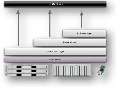
Services Models:
Cloud Computing comprises three different service models, namely Infrastructure-as-a-Service (IaaS), Platform-as-a-Service (PaaS), and Software-as-a-Service (SaaS). The three service models or layer are completed by an end user layer that encapsulates the end user perspective on cloud services. The model is shown in figure below. If a cloud user accesses services on the infrastructure layer, for instance, she can run her own applications on the resources of a cloud infrastructure and remain responsible for the support, maintenance, and security of these applications herself. If she accesses a service on the application layer, these tasks are normally taken care of by the cloud service provider.[6]
Figure 3: Structure of service models
Conference Chair:Prof.Dr.G.Manoj Someswar, Director General, Global Research Academy,
1.
Achieve economies of scale
– increase volume output or productivity with fewer people. Your cost per unit, project or product plummets.2.
Reduce
spending on
technology
infrastructure.
Maintain easy access to your information with minimal upfront spending. Pay as you go (weekly, quarterly or yearly), based on demand.3.
Globalize your workforce on the
cheap.
People worldwide can access the cloud, provided they have an Internet connection.4.
Streamline processes.
Get more work done in less time with less people.5.
Reduce capital costs.
There’s no need to spend big money on hardware, software or licensing fees.[7]6.
Improve accessibility.
You have access anytime, anywhere, making your life so much easier!7.
Monitor projects more effectively.
Stay within budget and ahead of completion cycle times.8.
Less personnel training is needed.
It takes fewer people to do more work on a cloud, with a minimal learning curve on hardware and software issues.9.
Minimize licensing new software.
Stretch and grow without the need to buy expensive software licenses or programs.
10.
Improve flexibility.
You can change direction without serious “people” or “financial” issues at stake.Advantages:
1.
Price:
Pay for only the resources used. 2.Security
:
Cloud instances are isolated in thenetwork from other instances for improved security.
3.
Performance:
Instances can be added instantly for improved performance. Clients have access to the total resources of the Cloud’s core hardware.[8]4.
Scalability:
Auto-deploy cloud instances when needed.5.
Uptime:
Uses multiple servers for maximu m redundancies. In case of server failure, instances can be automatically created on another server.6.
Control:
Able to login from any location. Server snapshot and a software library lets you deploy custom instances.7.
Traffic:
Deals with spike in traffic with quick deployment of additional instances to handle the load.LITERATURE SURVEY
Conference Chair:Prof.Dr.G.Manoj Someswar, Director General, Global Research Academy,
The model generates probabilistic proofs of possession by sampling random sets of blocks from the server, which drastically reduces I/O costs.[9] The client maintains a constant amount of metadata to verify the proof. The challenge/response protocol transmits a small, constant amount of data, which minimize s network communication. Thus, the PDP model for remote data checking is lightweight and supports large data sets in distributed storage systems. The model is also robust in that it incorporates mechanisms for mitigating arbitrary amounts of data corruption. We present two provably-secure PDP schemes that are more efficient than previous solutions. In particular, the overhead at the server is low (or even constant), as opposed to linear in the size of the data. We then propose a generic transformation that adds robustness to any remote data checking scheme based on spot checking. Experiments using our implementation verify the practicality of PDP and reveal that the performance of PDP is bounded by disk I/O and not by cryptographic computation. Finally, we conduct an in-depth experimen t a l evaluation to study the tradeoffs in performance, security, and space overheads when.[10]
A proof of retrievability (POR) is a compact proof by a file system (prover) to a client (verifier) that a target file F is intact, in the sense that the client can fully recover it. As PORs incur lower communication complexity than transmission of F itself, they are an attractive building block for high-assurance remote storage systems.
In this research paper, we propose a theoretical framework for the design of PORs. Our framework improves the previously proposed POR constructions of Juels -Kaliski and Shacham-Waters, and also sheds light on the conceptual limitations of previous theoretical models for PORs. It supports a fully Byzantine adversarial model, carrying only the restriction---fundamental to all PORs ---that the adversary's error rate be bounded when the client seeks to extract F. We propose a new variant on the Juels -Kaliski protocol and describe a prototype implementation. We demonstrate practical encoding even for files F whose size exceeds that of client main memory.[11]
Remote Data Checking (RDC) is a technique by which clients can establish that data outsourced at untrusted servers remains intact over time. RDC is useful as a prevention tool, allowing clients to periodically check if data has been damaged, and as a repair tool whenever damage has been detected. Initially proposed in the context of a single server, RDC was later extended to verify data integrity in distributed storage systems that rely on replication and on erasure coding to store data redundantly at multiple servers. Recently, a technique was proposed to add redundancy based on network coding, which offers interesting tradeoffs because of its remarkably low communication overhead to repair corrupt servers.[12]
Conference Chair:Prof.Dr.G.Manoj Someswar, Director General, Global Research Academy,
take a holistic look and initiate the investigation of RDC schemes for distributed systems that rely on network coding to minimize the combined costs of both the prevention and repair phases. We propose RDC-NC, a novel secure and efficient RDC scheme for network coding-based distributed storage systems. RDC-NC mitigates new attacks that stem from the underlying principle of network coding. The scheme is able to preserve in an adversarial setting the minima l communication overhead of the repair component achieved by network coding in a benign setting. We implement our scheme and experimenta lly show that it is computationally inexpensive for both clients and servers.[13]
To protect outsourced data in cloud storage against corruptions, adding fault tolerance to cloud storage, along with efficient data integrity checking and recovery procedures, becomes critical. Regenerating codes provide fault tolerance by striping data across multiple servers, while using less repair traffic than traditional erasure codes during failure recovery. Therefore, we study the problem of remotely checking the integrity of regenerating-coded data against corruptions under a real-life cloud storage setting. We design and implement a practical data integrity protection (DIP) scheme for a specific regenerating code, while preserving its intrinsic properties of fault tolerance and repair-traffic saving. Our DIP scheme is designed under a mobile Byzantine adversarial model, and enables a client to feasibly verify the integrity of random
subsets of outsourced data against general or malicious corruptions. It works under the simple assumption of thin-cloud storage and allows different parameters to be fine-tuned for a performance-security trade-off. We impleme n t and evaluate the overhead of our DIP scheme in a real cloud storage testbed under different parameter choices. We further analyze the security strengths of our DIP scheme via mathematical models. We demonstrate that remote integrity checking can be feasibly integrated into regenerating codes in practical deployment.[14]
Conference Chair:Prof.Dr.G.Manoj Someswar, Director General, Global Research Academy,
surviving nodes. We show that regenerating codes can significantly reduce the repair bandwidth. Further, we show that there is a fundamental tradeoff between storage and repair bandwidth which we theoretically characterize using flow arguments on an appropriately constructed graph. By invoking constructive results in network coding, we introduce regenerating codes that can achieve any point in this optimal tradeoff.[15]
SYSTEM STUDY
FEASIBILITY STUDY
The feasibility of the project is analyzed in this phase and busines s proposal is put forth with a very general plan for the project and some cost estimates. During system analysis the feasibility study of the proposed system is to be carried out. This is to ensure that the proposed system is not a burden to the company. For feasibility analysis, some understanding of the major requirements for the system is essential.
Three key considerations involved in the feasibility analysis are
ECONOMICA L FEASIBILITY
TECHNICA L FEASIBILITY
SOCIAL FEASIBILITY
ECONOMICAL FEASIBILITY
This study is carried out to check the economic impact that the system will have on the organization. The amount of fund that the company can pour into the research and development of the system is limited. The expenditures must be justified.
Thus the developed system as well within the budget and this was achieved because most of the technologies used are freely available. Only the customized products had to be purchased.
TECHNICAL FEASIBILITY
This study is carried out to check the technical feasibility, that is, the technical requirements of the system. Any system developed must not have a high demand on the available technical resources. This will lead to high demands on the available technical resources. This will lead to high demands being placed on the client. The developed system must have a modest requirement, as only minimal or null changes are required for implementing this system.
SOCIAL FEASIBILITY
The aspect of study is to check the level of acceptance of the system by the user. This includes the process of training the user to use the system efficiently. The user must not feel threatened by the system, instead must accept it as a necessity. The level of acceptance by the users solely depends on the methods that are employed to educate the user about the system and to make him familiar with it. His level of confidence must be raised so that he is also able to make some constructive criticism, which is welcomed , as he is the final user of the system.
SYSTEM DESIGN
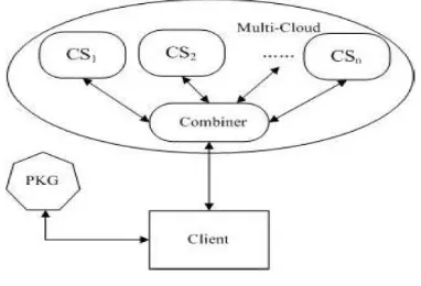
Conference Chair:Prof.Dr.G.Manoj Someswar, Director General, Global Research Academy,
Figure 4: System Architecture
DATA FLOW DIAGRAM:
1. The DFD is also called as bubble chart. It is a simple graphical formalism that can be used to represent a system in terms of input data to the system, various processing carried out on this data, and the output data is generated by this system.
2. The data flow diagram (DFD) is one of the most important modeling tools. It is used to model the system components. These components are the system process, the data used by the process, an external entity that interacts with the system and the informatio n flows in the system.
3. DFD shows how the information moves through the system and how it is modified by a series of transformations. It is a graphical technique that depicts information flow and the transformations that are applied as data moves from input to output.
4. DFD is also known as bubble chart. A DFD may be used to represent a system at any level
of abstraction. DFD may be partitioned into levels that represent increasing informatio n flow and functional detail.
login Registration
DataOwner User
Split the Files into Blocks
Upload the Blocks into Multicloud Server
File Upload
View the Files
Download the Files Encrypt the File Blocks
Decrypt the File Blocks Verifier Multi Cloud Server
View the Files
Accept the FileBlocks Get the Decryption Key
Decrypt All the File Blocks
Verify the Files
Enter the Key from Mail
Figure 5: Data Flow Diagram
UML DIAGRAMS
UML stands for Unified Modeling Language. UML is a standardized general-purpose modeling language in the field of object-oriented software engineering. The standard is managed, and was created by, the Object Management Group.
Conference Chair:Prof.Dr.G.Manoj Someswar, Director General, Global Research Academy,
The Unified Modeling Language is a standard language for specifying, Visualizatio n , Constructing and documenting the artifacts of software system, as well as for business modeling and other non-software systems.
The UML represents a collection of best engineering practices that have proven successful in the modeling of large and complex systems.
The UML is a very important part of developing objects oriented software and the software development process. The UML uses mostly graphical notations to express the design of software projects.
GOALS:
The Primary goals in the design of the UM L are as follows:
1. Provide users a ready-to-use, expressive visual modeling Language so that they can develop and exchange meaningful models. 2. Provide extendibility and specialization
mechanisms to extend the core concepts. 3. Be independent of particular programmin g
languages and development process. 4. Provide a formal basis for understanding the
modeling language.
5. Encourage the growth of OO tools market. 6. Support higher level development concepts
such as collaborations, frameworks, patterns and components.
7. Integrate best practices.
USE CASE DIAGRAM:
A use case diagram in the Unified Modeling Language (UML) is a type of behavioral diagram defined by and created from a Use-case analysis. Its
purpose is to present a graphical overview of the functionality provided by a system in terms of actors, their goals (represented as use cases), and any dependencies between those use cases. The main purpose of a use case diagram is to show what system functions are performed for which actor. Roles of the actors in the system can be depicted.
Data Owner
User Registration
Enter the Secret Key & Download the Files File Upload
Split the Files into Blocks & Uploaded to Multi-cloud server
Accept the Files Blocks
Get the Decryption Key & Decrypt All the FIle Blocks
Verifies the Files
View the Files
Decrypt the File Blocks Multi Cloud Server
Verifier
Figure 6: Use Case Diagram
CLASS DIAGRAM:
Conference Chair:Prof.Dr.G.Manoj Someswar, Director General, Global Research Academy,
Figure 7: Class Diagram
SEQUENCE DIAGRAM:
A sequence diagram in Unified Modeling Language (UML) is a kind of interaction diagram that shows how processes operate with one another and in what order. It is a construct of a Message Sequence Chart. Sequence diagrams are sometimes called event diagrams, event scenarios, and timing diagrams.
DataOwner Verifier
Registration
User MultiCloud Server
Registration
File Upload
Split & Encrypt the files into Blocks
Upload the Encrypted FileBlocks
View and Accept the File Blocks
Get the Decryption Key for each Block
Decrypt and Verify the Files
View and Decrypt the File Blocks
Enter the Secret Key from Mail
Download the File
Figure 8: Sequence Diagram
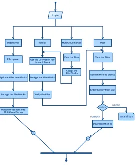
ACTIVITY DIAGRAM:
Activity diagrams are graphical representations of workflows of stepwise activities and actions with support for choice, iteration and concurrency. In the Unified Modeling Language, activity diagrams can be used to describe the business and operational step -by-step workflows of components in a system. An activity diagram shows the overall flow of control.
A
Login
User
Encrypt the File Blocks DataOwner
View the Files
Split the Files into Blocks
Upload the Blocks into MultiCloud Server
CHECK CORRECT
WRONG
Decrypt the File Blocks
Enter the Key from Mail
Download the File
invalid key
File Upload
A
Verifier MultiCloud Server
View the Files Accept the File Blocks Get the Decryption key
for each Block
Decrypt the File Blocks
Verify the Files
Figure 9: Activity Diagram
INPUT DESIGN
Conference Chair:Prof.Dr.G.Manoj Someswar, Director General, Global Research Academy,
The input is designed in such a way so that it provides security and ease of use with retaining the privacy. Input Design considered the following things:
What data should be given as input?
How the data should be arranged or coded?
The dialog to guide the operating personnel in providing input.
Methods for preparing input validations and steps to follow when error occur.
OBJECTIVES
1. Input Design is the process of converting a user-oriented description of the input into a computer-based system. This design is important to avoid errors in the data input process and show the correct direction to the management for getting correct informatio n from the computerized system.
2. It is achieved by creating user-friendly screens for the data entry to handle large volume of data. The goal of designing input is to make data entry easier and to be free from errors. The data entry screen is designed in such a way that all the data manipulates can be performed. It also provides record viewing facilities. 3. When the data is entered it will check for its validity. Data can be entered with the help of screens. Appropriate messages are provided as when needed so that the user will not be in maize of instant. Thus the objective of input design is to create an input layout that is easy to follow
OUTPUT DESIGN
A quality output is one, which meets the requirements of the end user and presents the information clearly. In any system results of processing are communicated to the users and to other system through outputs. In output design it is determined how the information is to be displaced for immediate need and also the hard copy output. It is the most important and direct source information to the user. Efficient and intelligent output design improves the system’s relationship to help user decision-making.
1. Designing computer output should proceed in an organized, well thought out manner; the right output must be developed while ensuring that each output element is designed so that people will find the system can use easily and effectively. When analysis design computer output, they should Identify the specific output that is needed to meet the requirements. 2. Select methods for presenting information.
3. Create document, report, or other formats that contain information produced by the system.
The output form of an information system should accomplish one or more of the following objectives.
Convey information about past activities, current status or projections of the
Future.
Signal important events, opportunities, problems, or warnings.
Trigger an action.
Conference Chair:Prof.Dr.G.Manoj Someswar, Director General, Global Research Academy,
SYSTEM ANALYSIS
EXISTING SYSTEM:
In cloud computing, remote data integrity checking is an important security problem. The clients’ massive data is outside his control. The malicious cloud server may corrupt the clients’ data in order to gain more benefits. The formal system model and security model are existing models.
In the PDP model, the verifier can check remote data integrity with a high probability. Based on the RSA, they designed two provably secure PDP schemes. PDP allows a verifier to verify the remote data integrity without retrieving or downloading the whole data. It is a probabilistic proof of possession by sampling random set of blocks from the server, which drastically reduces I/O costs. The verifier only maintains small metadata to perform the integrity checking. PDP is an interesting remote data integrity checking model.
In POR, the verifier can check the remote data integrity and retrieve the remote data at any time . On some cases, the client may delegate the remote data integrity checking task to the third party. It results in the third party auditing in cloud computing
DISADVANTAGES
OF
EXISTING
SYSTEM:
Does not provide efficiency in remote data integrity checking.
More expensive.
The existing system provides less flexibility.
PROPOSED SYSTEM:
Remote data integrity checking is of crucial importance in cloud storage. In multi-clou d environment, distributed provable data possession is an important element to secure the remote data. we propose a novel remote data integrity checking model: ID-DPDP (identity-based distributed provable data possession) in multi-cloud storage. The proposed ID-DPDP protocol is provably secure under the hardness assumption of the standard CDH (computational Diffi Hellman) problem. The proposed ID-DPDP protocol can realize private verification, delegated verification and public verification.
ADVANTAGES OF PROPOSED SYSTEM:
The distributed cloud storage is indispensable.
Efficient and Flexible.
Elimination of the certificate management.
SYSTEM TESTING
Conference Chair:Prof.Dr.G.Manoj Someswar, Director General, Global Research Academy,
and does not fail in an unacceptable manner. There are various types of test. Each test type addresses a specific testing requirement.
TYPES OF TESTS
Unit testing
Unit testing involves the design of test cases that validate that the internal program logic is functioning properly, and that program inputs produce valid outputs. All decision branches and internal code flow should be validated. It is the testing of individual software units of the application .it is done after the completion of an individual unit before integration. This is a structural testing, that relies on knowledge of its construction and is invasive. Unit tests perform basic tests at component level and test a specific business process, application, and/or system configuration. Unit tests ensure that each unique path of a business process performs accurately to the documented specifications and contains clearly defined inputs and expected results.
Integration testing
Integration tests are designed to test integrated software components to determine if they actually run as one program. Testing is event driven and is more concerned with the basic outcome of screens or fields. Integration tests demonstrate that although the components were individually satisfaction, as shown by successfully unit testing, the combination of components is correct and consistent. Integration testing is specifically aimed at exposing the problems that arise from the combination of components.
Functional test
Functional tests provide systematic demonstrations that functions tested are available as specified by the business and technical requirements, system documentation, and user manuals.
Functional testing is centered on the following items: Valid Input : identified classes of valid input must be accepted.
Invalid Input : identified classes of invalid input must be rejected.
Functions : identified functions must be exercised.
Output : identified classes of application outputs must be exercised.
Systems/Procedures: interfacing systems or procedures must be invoked.
Organization and preparation of functional tests is focused on requirements, key functions, or special test cases. In addition, systematic coverage pertaining to identify Business process flows; data fields, predefined processes, and successive processes must be considered for testing. Before functional testing is complete, additional tests are identified and the effective value of current tests is determined.
System Test
Conference Chair:Prof.Dr.G.Manoj Someswar, Director General, Global Research Academy,
oriented system integration test. System testing is based on process descriptions and flows, emphasizing pre-driven process links and integration points.
White Box Testing
White Box Testing is a testing in which in which the software tester has knowledge of the inner workings, structure and language of the software, or at least its purpose. It is purpose. It is used to test areas that cannot be reached from a black box level.
Black Box Testing
Black Box Testing is testing the software without any knowledge of the inner workings, structure or language of the module being tested. Black box tests, as most other kinds of tests, must be written from a definitive source document, such as specification or requirements document, such as specification or requirements document. It is a testing in which the software under test is treated, as a black box .you cannot “see” into it. The test provides inputs and responds to outputs without considering how the software works.
Unit Testing:
Unit testing is usually conducted as part of a combined code and unit test phase of the software lifecycle, although it is not uncommon for coding and unit testing to be conducted as two distinct phases.
Test strategy and approach
Field testing will be performed manually and functional tests will be written in detail.
Test objectives
All field entries must work properly.
Pages must be activated from the identified link.
The entry screen, messages and responses must not be delayed.
Features to be tested
Verify that the entries are of the correct format
No duplicate entries should be allowed
All links should take the user to the correct page.
Integration Testing
Software integration testing is the incremental integration testing of two or more integrated software components on a single platform to produce failures caused by interface defects.
The task of the integration test is to check that components or software applications, e.g. components in a software system or – one step up – software applications at the company level – interact without error.
Test Results:
All the test cases mentioned above passed successfully. No defects encountered.Acceptance Testing
User Acceptance Testing is a critical phase of any project and requires significant participation by the end user. It also ensures that the system meets the functional requirements.
Conference Chair:Prof.Dr.G.Manoj Someswar, Director General, Global Research Academy,
IMPLEMENTATION
MODULES
1. Cloud User Module 2. Verifier Module
3. Private Key Generator Module 4. Cloud Server Module
MODULES DESCRIPTION:
Cloud User Module:
An entity, which has massive data to be stored on the multi-cloud for maintenance and computation, can be either individual consumer or corporation.
In this module each user registers his user details for using files. Only registered user can able to login in cloud server.
In this module user view a block of uploaded files that is accepted by cloud servers and Verified by verifier in the multi cloud Server.
This module allows the user to download the uploaded from multi cloud server and that file verified by verifier file using his identity key to download the decrypted data.
Verifier Module:
The public verifier is able to correctly check the integrity of shared data. The public verifier can audit the integrity of shared data from multi-cloud with whole Data and accept the file.
In this module public auditor check all files integrity And accept the files to cloud.
Private Key Generator Module
An entity, when receiving the identity, it outputs the corresponding private key.
The concrete ID-DPDP construction mainly comes from the signature, provable data possession and distributed computing. The signature relates the client’s identity with his private key.
Distributed computing is used to store the client’s data on multi-cloud servers. At the same time, distributed computing is also used to combine the multi-cloud servers’ responses to respond the verifier’s challenge.
Based on the provable data possession protocol, the ID-DPDP protocol is constructed by making use of the signature and distributed computing.
Cloud Server Module:
An entity, which is managed by cloud service provider, has significant storage space and computation resource to maintain the clients’ data.
In this module each server from multi cloud verifies the file block and accepts the block of files to verify the verifier.
RESULTS & CONCLUSION
Conference Chair:Prof.Dr.G.Manoj Someswar, Director General, Global Research Academy,
verification, delegated verification and public verification based on the client’s authorization.
REFERENCES
[1] G. Ateniese, R. Burns, R. Curtmola, J. Herring, L. Kissner, Z. Peterson, D. Song, “Provable Data Possession at Untrusted Stores”, CCS’07, pp. 598-609, 2007.
[2] G. Ateniese, R. DiPietro, L. V. Mancini, G. Tsudik, “Scalable and Efficient Provable Data Possession”,
SecureComm 2008, 2008.
[3] C. C. Erway, A. Kupcu, C. Papamanthou, R. Tamassia, “Dynamic Provable Data Possession”,
CCS’09, pp. 213-222, 2009.
[8] F. Seb´e, J. Domingo-Ferrer, A. Mart´ınez-Ballest´e, Y. Deswarte, J. Quisquater, “Efficien t
Remote Data Integrity checking in Critic a l Information Infrastructures”, IEEE Transactions on
Knowledge and Data Engineering, 20(8), pp. 1-6,
2008.
[9] H.Q. Wang, “Proxy Provable Data Possession in Public Clouds,” IEEE Transactions on Services
Computing, 2012.
http://doi.ieeecomputersociety.org/10.1109/TSC.201
2.35
[10] Y. Zhu, H. Hu, G.J. Ahn, M. Yu, “Cooperative Provable Data Possession for Integrity Verification in Multicloud Storage”, IEEE Transactions on Parallel
and Distributed Systems, 23(12), pp. 2231-2244, 2012.
[11] Y. Zhu, H. Wang, Z. Hu, G. J. Ahn, H. Hu, S. S. Yau, “Efficient Provable Data Possession for Hybrid Clouds”, CCS’10, pp. 756-758, 2010.
[4] R. Curtmola, O. Khan, R. Burns, G. Ateniese, “MR-PDP: Multiple-Replica Provable Data Possession”, ICDCS’08, pp. 411-420, 2008.
[5] A. F. Barsoum, M. A. Hasan, “Provable Possession and Replication of Data over Cloud Servers”, CACR, University of Waterloo, Report2010/32,20 1 0. Available at
http://www.cacr.math.uwaterloo.ca/techreports
/2010/cacr2010-32.pdf.
[6] Z. Hao, N. Yu, “A Multiple-Replica Remote Data Possession Checking Protocol with Public Verifiability”, 2010 Second International Symposium
on Data, Privacy, and E-Commerce, pp. 84-89, 2010.
[7] A. F. Barsoum, M. A. Hasan, “On Verifyin g Dynamic Multiple Data Copies over Cloud Servers”,
IACR eprint report 447, 2011. Available at
http://eprint.iacr.org/2011/447.pdf.
[12] A. Juels, B. S. Kaliski Jr., “PORs: Proofs of Retrievability for Large Files”, CCS’07, pp. 584-597, 2007.
[13] H. Shacham, B. Waters, “Compact Proofs of Retrievability”, ASIACRYPT 2008, LNCS 5350, pp. 90-107, 2008.
[14] K. D. Bowers, A. Juels, A. Oprea, “Proofs of Retrievability: Theory and Implementation ”,
CCSW’09, pp. 43-54, 2009.
[15] Q. Zheng, S. Xu. Fair and Dynamic Proofs of Retrievability. CODASPY’