Installation Procedure Manual
DECEMBER, 1997
NEC America, Inc.
NEC America, Inc. has prepared this document for use by its em-ployees and customers. The information contained herein is the property of NEC America, Inc. and shall not be reproduced without prior written approval from NEC America, Inc.
NEAX and Dterm are registered trademarks of NEC Corporation.
Copyright 1997
NEC America, Inc.
ADDENDUM-001 ADDENDUM-002 ADDENDUM-003 ADDENDUM-004
DATE JANUARY, 1999 DATE DATE DATE
ADDENDUM-005 ADDENDUM-006 ADDENDUM-007 ADDENDUM-008
DATE DATE DATE DATE
NEAX2000 IVS
Installation Procedure Manual Addendum Revision Sheet 1/3
ADDENDUM-001 ADDENDUM-002 ADDENDUM-003 ADDENDUM-004
DATE JANUARY, 1999 DATE DATE DATE
ADDENDUM-005 ADDENDUM-006 ADDENDUM-007 ADDENDUM-008
DATE DATE DATE DATE
NEAX2000 IVS
Installation Procedure Manual Addendum Revision Sheet 2/3
ND-45492 (E) ISSUE 2
ADDENDUM-001 ADDENDUM-002 ADDENDUM-003 ADDENDUM-004
DATE JANUARY, 1999 DATE DATE DATE
ADDENDUM-005 ADDENDUM-006 ADDENDUM-007 ADDENDUM-008
DATE DATE DATE DATE
NEAX2000 IVS
Installation Procedure Manual Addendum Revision Sheet 3/3
143 144
145
146 147
148
149 150
151
152 153
154
NEAX2000 IVS
Installation Procedure Manual
TABLE OF CONTENTS
Page
ND-45492 (E) TABLE OF CONTENTS
Page i Revision 2.0
LIST OF FIGURES . . . iii
LIST OF TABLES . . . vi
SAFETY CONSIDERATIONS. . . vii
REGULATORY INFORMATION . . . ix
1. Regulatory Requirements . . . ix
2. FCC Part 15 Requirements . . . ix
3. FCC Part 68 Registration . . . ix
3.1 Company Notification . . . ix
3.2 Service Requirements. . . x
3.3 Location of FCC Compliance Labels . . . x
4. Direct-Inward Dialing (DID) Calls . . . .x
5. Regulatory Information on Single-Line Analog Telephones. . . xi
6. Hearing Aid Compatibility. . . xi
7. Industry Canada CS-03 . . . xi
8. Safety Certifications . . . xii
8.1 Safety Considerations . . . xii
CHAPTER 1 INTRODUCTION . . . .1
1. PURPOSE . . . .1
2. REFERENCE MANUAL . . . .1
3. HOW TO FOLLOW THIS MANUAL . . . .2
3.1 SCOPE OF INSTALLATION PROCEDURES. . . .2
CHAPTER 2 GENERAL INFORMATION . . . .3
1. TRUNKING DIAGRAM. . . .3
2. SYSTEM CONFIGURATIONS. . . .5
CHAPTER 3 INSTALLATION PROCEDURE . . . .11
1. PRECAUTIONS . . . .11
1.1 GROUNDING REQUIREMENTS . . . .11
1.1.1 EQUIPMENT GROUND . . . .11
1.1.2 SUPPLEMENTARY GROUND . . . .11
1.2 STATIC ELECTRICITY PRECAUTIONS . . . .12
NAP 200-001 Unpacking . . . .18
NAP 200-002 Marking and Drilling . . . .20
NAP 200-003 Installation of Main Equipment. . . .23
NAP 200-004 Installation of Peripheral Equipment . . . .60
NAP 200-005 Connection of Battery . . . .72
NAP 200-006 Cable Running to the MDF . . . .79
NAP 200-007 Termination of Cables on the MDF . . . .86
NAP 200-008 Mounting of Circuit Cards . . . .142
NAP 200-009 Installation of Back up MP System . . . .145
NAP 200-010 System Initialization and System Data Entry . . . .151
NAP 200-011 Operation Test . . . .154
NAP 200-012 Cleaning and Visual Check . . . .155
ND-45492 (E) LIST OF FIGURES Page iii Revision 2.0
Figure 1-2 Scope of Installation Works . . . 2
Figure 2-1 PBX Trunking Diagram . . . 3
Figure 2-2 1-PIM Configuration for Floor Standing Installation . . . 5
Figure 2-3 2-PIM Configuration for Floor Standing Installation . . . 6
Figure 2-4 8-PIM Configuration for Floor Standing Installation . . . 7
Figure 2-5 1-PIM Configuration for Wall-Mounting Installation . . . 8
Figure 2-6 1-PIM Configuration for 19-inch Rack-Mounting Installation . . . 9
Figure 2-7 1-PIM Configuration for Desk Top Installation . . . 10
Figure 3-1 Static Electricity Precautions (1 of 2) . . . 12
Figure 3-1 Static Electricity Precautions (2 of 2) . . . 13
Figure 3-2 Procedure Flowchart (1 of 2) . . . 16
Figure 3-2 Procedure Flowchart (2 of 2). . . 17
Figure 001-1 Unpacking of Main Equipment . . . 19
Figure 002-1 Floor Marking for Main Equipment . . . 20
Figure 002-2 Wall Mounting Points . . . 21
Figure 002-3 Instruction for Anchor Bolt . . . 22
Figure 003-1 Connection of RACK PARTS and BASE . . . 23
Figure 003-2 Connection of RACK PARTS . . . 24
Figure 003-3 Installation of Screws onto RACK PARTS . . . 25
Figure 003-4 Securing of the BASE . . . 26
Figure 003-5 Connection of the PIM and the RACK PARTS. . . 27
Figure 003-6 Mounting of the PIM . . . 28
Figure 003-7 Connection of PIMs . . . 29
Figure 003-8 Mounting of the TOP COVER . . . 30
Figure 003-9 Cable Connection on the PZ-PW86 . . . 31
Figure 003-9 Cable Connection on the PZ-PW86 (Continued) . . . 32
Figure 003-9 Cable Connection on the PZ-PW86 (Continued) . . . 33
Figure 003-10 Cable Connection between the PZ-PW86 and the BWB . . . 34
Figure 003-11 AC CORD-B and AC Power Cable Wiring . . . 35
Figure 003-12 Screwing the AC CORD-B to the Terminals . . . 36
Figure 003-13 AC Power Cable Wiring for Two-Frame Configuration . . . 37
Figure 003-14 PWR CA-A . . . 38
Figure 003-15 Connection of PWR CA-A Cables (1 of 2) . . . 39
Figure 003-15 Connection of PWR CA-A Cables (2 of 2) . . . 40
Figure 003-16 Mounting of the BUS Cards . . . 41
Figure 003-17 BUS Cable . . . 42
Figure 003-18 Connection of the BUS Cables . . . 43
Figure 003-19 BUS Cable . . . 44
Figure 003-20 Connection of the BUS Cables . . . 45
Figure 003-21 Screwing the RACK PARTS to a Wall . . . 47
Figure 003-22 Connecting the RACK PARTS and the BASE . . . 48
Figure 003-23 Mounting the PIM to the RACK PARTS . . . 49
Figure 003-24 Screwing the PIM to the RACK PARTS . . . 50
Figure 003-25 Connecting the Covers and AC CORD-A to the PIM . . . 52
Figure 003-26 Mounting the PIM to the 19-Inch Rack (1 of 2) . . . 53
Figure 003-26 Mounting the PIM to the 19-Inch Rack (2 of 2) . . . 54
Figure 003-27 Mounting of the TOP COVER . . . 55
Figure 003-28 Connecting the BASE to the PIM . . . 56
Figure 004-1 Location of the Cable Hole . . . 60
Figure 004-2 Mounting of the Handset Support to the SN610 ATTCON. . . 61
Figure 004-3 Jack Set Installation for the SN610 ATTCON . . . 62
Figure 004-4 Switch Setting on the SN610 ATTCON (1 of 2) . . . 63
Figure 004-4 Switch Setting on the SN610/611/615 ATTCON (2 of 2) . . . 64
Figure 004-5 Cable Connection to the SN610 ATTCON . . . 65
Figure 004-6 Mounting of the Handset Support to the SN716 DESKCON . . . 66
Figure 004-7 Headset Installation for the SN716 DESKCON . . . 67
Figure 004-8 Cable Connection to the SN716 DESKCON . . . 68
Figure 004-9 AC-DC ADAPTER Connection to the SN716 DESKCON . . . 69
Figure 004-10 Mounting PW00 Card into PIM. . . 70
Figure 004-11 PW00 Card connection to the SN716 DESKCON . . . 71
Figure 005-1 Internal Battery Mounting . . . 74
Figure 005-2 Internal Battery Connection . . . 75
Figure 005-3 Internal Battery Connection for a Multiple PIM Configuration . . . 76
Figure 005-4 Battery Mounting into the BATTM . . . 77
Figure 005-5 Battery Connection in the BATTM for a Multiple PIM Configuration . . . 78
Figure 006-1 MDF Cable . . . 79
Figure 006-2 Cable Running to the External MDF (1 of 2) . . . 81
Figure 006-3 Making Cable Hole on the PIM . . . 82
Figure 006-4 Cable Running to the External MDF (2 of 2) . . . 83
Figure 006-5 Cable Running to the MDFM . . . 84
Figure 006-6 Example of MDF Cable Connection to the MDFM . . . 85
Figure 007-1 Location of the Card Slots and the LTC Connectors . . . 86
Figure 007-2 Location of each LEN (1 of 2) . . . 87
Figure 007-3 Location of each LEN (2 of 2) . . . 88
Figure 007-4 LTC Connector Pin Arrangement (1 of 8) . . . 89
Figure 007-5 LTC Connector Pin Arrangement (2 of 8) . . . 90
Figure 007-6 LTC Connector Pin Arrangement (3 of 8) . . . 91
Figure 007-7 LTC Connector Pin Arrangment (4 of 8) . . . 92
Figure 007-8 LTC Connector Pin Arrangement (5 of 8) . . . 93
Figure 007-9 LTC Connector Pin Arrangement (6 of 8) . . . 94
Figure 007-10 LTC Connector Pin Arrangement (7 of 8) . . . 95
Figure 007-11 LTC Connector Pin Arrangement (8 of 8) . . . 96
Figure 007-12 MDF Cross Connection for a 4 Line C.O. Trunk Card (PN-4COT) . . . 101
Figure 007-13 MDF Cross Connection for a 4W E&M Trunk Card (PN-2ODT) (1 of 2) . . . 102
Figure 007-14 MDF Cross Connection for a 4W E&M Trunk Card (PN-2ODT) (2 of 2) . . . 103
Figure 007-15 MDF Cross Connection for a 2W E&M Trunk Card (PN-2ODT) (1 of 2) . . . 104
Figure 007-16 MDF Cross Connection for a 2W E&M Trunk Card (PN-2ODT) (2 of 2) . . . 105
Figure 007-17 MDF Cross Connection for a 2 Line DID Trunk Card (PN-AUCA) . . . 106
Figure 007-18 MDF Cross Connection for a 4 Line DID Trunk Card (PN-4DITB). . . 107
Figure 007-19 MDF Cross Connection for a Single Line Telephone (Standard Line) . . . 108
Figure 007-20 MDF Cross Connection for a Single Line Telephone (Long Line) . . . 109
Figure 007-21 MDF Cross Connection for a Dterm/DSS Console (Standard Line) . . . 110
Figure 007-22 MDF Cross Connection for a Dterm/DSS Console (Long Line) . . . 111
Figure 007-23 MDF Cross Connection for an SN610 ATTCON (1 of 3) . . . 112
Figure 007-23 MDF Cross Connection for an SN610 ATTCON (2 of 3) . . . 113
Figure 007-23 MDF Cross Connection for an SN610 ATTCON (3 of 3) . . . 114
Figure 007-24 MDF Cross Connection for a SN716 DESKCON (1 of 2) . . . 115
ND-45492 (E) LIST OF FIGURES Page v Revision 2.0
Figure 007-26 Outline of the External TAS Indicator Connection . . . 118
Figure 007-27 MDF Cross Connection for a TAS Indicator with a Battery . . . 119
Figure 007-28 MDF Cross Connection for a TAS Indicator with a Battery (Ground Start) . . . 120
Figure 007-29 Outline of the Paging Equipment Connection . . . 121
Figure 007-30 MDF Cross Connection for a Paging Equipment (1 of 2). . . 122
Figure 007-31 MDF Cross Connection for Paging Equipment (2 of 2) . . . 123
Figure 007-32 Outline of the External Tone Source Connection. . . 125
Figure 007-33 MDF Cross Connection for External Tone Source Equipment (1 of 2) . . . 126
Figure 007-34 MDF Cross Connection for External Tone Source Equipment (2 of 2) . . . 127
Figure 007-35 Connecting a Tone Source Supplied with D.C. . . 128
Figure 007-36 MDF Cross Connection for External BGM Sources . . . 129
Figure 007-37 Cable Connection between PN-TNTA and External BGM Sources . . . 130
Figure 007-38 Outline of the PFT (PN-AUCA) Connection . . . 131
Figure 007-39 MDF Cross Connection for the PFT (PN-AUCA) (1 of 2). . . 132
Figure 007-40 MDF Cross Connection for the PFT (PN-AUCA) (2 of 2). . . 133
Figure 007-41 Outline of the PFT (PZ-8PFTA) Connection . . . 134
Figure 007-42 Connection of 25-Pair Cable and PZ-8PFTA . . . 135
Figure 007-43 Mounting the PZ-8PFTA Card to the PIM . . . 136
Figure 007-44 PFT Connector Pin Assignment. . . 137
Figure 007-45 MDF Cross Connection for the PFT (PZ-8PFTA) (1 of 2) . . . 138
Figure 007-46 MDF Cross Connection for the PFT (PZ-8PFTA) (2 of 2) . . . 139
Figure 007-47 MDF Cross Connection for an Alarm Display Panel . . . 140
Figure 007-48 MDF Cross Connection for an Alarm Display Panel (Continued) . . . 141
Figure 008-1 Lamp Indication on the PZ-PW86 Card . . . 142
Figure 008-2 Mounting of the Circuit Cards. . . 143
Figure 008-3 Installation of the Card Stopper . . . 144
Figure 009-1 Mounting Location of the PN-CP02 Card. . . 145
Figure 009-2 Cable Connection between MP Cards . . . 146
Figure 009-3 MDF Cross Connection for the PFT (PZ-8PFTA) . . . 147
Table 3-1 Procedure for Unplugging/Plugging Circuit Cards . . . 14
Table 003-1 Recommended Fasteners . . . 46
Table 006-1 MDF Cables for each PIM . . . 80
Table 007-1 LTC Connector Accommodation . . . 86
Table 007-2 LTC0-LTC2 MDF Cross Connection Information (1 of 4). . . 97
Table 007-3 LTC0-LTC2 MDF Cross Connection Information (2 of 4). . . 98
Table 007-4 LTC0-LTC2 MDF Cross Connection Information (3 of 4). . . 99
ND-45492 (E) SAFETY CONSIDERATIONS Page vii Revision 2.0 (1) Never install telephone wiring during a lightning storm.
(2) Never install telephone jacks in wet locations unless the jack is specifically designed for wet loca-tions.
(3) Never touch uninsulated telephone wires or terminals unless the telephone line has been discon-nected at the network interface.
(4) Use caution when installing or moving telephone lines.
When using your telephone equipment, basic safety precautions should always be followed to reduce the risk of fire, electric shock and injury, including the following:
(5) Read and understand all instructions.
(6) Follow all warnings and instructions marked on the product.
(7) Unplug this product from the wall outlet before cleaning. Do not use liquid cleaners or aerosol cleaners. Use a damp cloth for cleaning.
(8) Do not use this product near water; for example, under water pipes near a bath tub, sink, or laun-dry tub, in a wet basement, or near a swimming pool.
(9) Do not place this product on an unstable cart, stand, or table. The product may fall, causing seri-ous damage to the product.
(10) Slots and openings in the cabinet and the back or bottom are provided for ventilation, to protect it from overheating. These openings must not be blocked or covered. The openings should never be blocked by placing the product on a bed, sofa, rug, or other similar surface. This product should never be placed near or over a radiator or heat register. This product should not be placed in a built-in installation unless proper ventilation is provided.
(11) This product should be operated only from the type of power source indicated on the marking la-bel. If you are not sure of the type of power source available, consult with your local power com-pany.
(12) This product normally connected with a three wire grounding type plug, a plug having a third (grounding) pin. This plug will only fit into a grounding type power outlet. This is a safety feature. If you are unable to insert the plug into the outlet, contact an electrician to replace your obsolete outlet. Do not defeat the safety purpose of the grounding type plug.
(13) Do not allow anything to rest on the power cord. Do not locate this product where the cord will be abused by persons walking on it.
(16) To reduce the risk of electric shock, do not disassemble this product, but take it to a qualified ser-viceman when some service or repair work is required. Opening or removing covers may expose you to dangerous voltages or other risks. Incorrect reassembly can cause electric shock when the appliance is subsequently used.
(17) Unplug this product from the wall outlet and refer servicing to qualified service personnel under the following conditions:
(a) When the power supply cord or plug is damaged or frayed.
(b) If liquid has been spilled into the product.
(c) If the product has been exposed to rain or water.
(d) If the product does not operate normally by following the operating instructions. Adjust only those controls, that are covered by the operating instructions because improper adjustment of other controls may result in damage and will often require extensive work by a qualified technician to restore the product to normal operation.
(e) If the product has been dropped or the cabinet has been damaged.
(f) If the product exhibits a distinct change in performance.
(18) Avoid using a telephone (other than a cordless type) during an electrical storm. There may be a remote risk of electric shock from lightning.
ND-45492 (E) REGULATORY INFORMATION Page ix Revision 2.0
The Federal Communications Commission (FCC) has established rules that permit the NEAX2000 IVS to be directly connected to the telephone network. A jack is provided on party lines or coin lines.
The telephone company may make changes in its technical operations and procedures. If such changes affect the compatibility or use of the NEAX2000 IVS, the telephone company is required to give adequate notice of the changes.
This equipment complies with the requirements in Part 15 of FCC Rules for a Class A computing device. Op-eration of this equipment in a residential area may cause unacceptable interference to radio and TV reception requiring the operator to take whatever steps are necessary to correct this interference.
2. FCC Part 15 Requirements
In compliance with FCC Part 15 Rules, the following statement is provided:
3. FCC Part 68 Registration 3.1 Company Notification
Before installing the NEAX2000 IVS to the telephone network, the telephone company must be provided with the following:
• Your telephone number
• The FCC registration numbers:
JAPAN USA
• PBX: AY5JPN-20542-PF-E AY5USA-21582-PF-E
• Hybrid: AY5JPN-20543-MF-E AY5USA-21583-MF-E
• Key system: AY5JPN-20586-KF-E AY5USA-21584-KF-E
The Ringer Equivalence Number is 1.6B; the required USOC jacks are RJ21X, RJ2EX, and RJ2GX. WARNING
In the event of equipment malfunction, all repairs will be performed by NEC or an authorized distributor of NEC. It is the responsibility of users requiring service to report the need for service to NEC or to one of their authorized distributors.
If the equipment causes harm to the telephone network, the telephone company will notify you in advance that temporary discontinuance of service may be required. If advance notice is not practical, the telephone company will notify the customer as soon as possible. Also, you will be advised of your right to file a complaint with the FCC if you believe it is necessary.
The telephone company may make changes in its facilities, equipment, operations, or procedures that affect the operation of the equipment. If this happens, the telephone company will provide advance notice in order for you to make necessary modifications in order to maintain uninterrupted service.
If trouble is experienced with this equipment, please contact NEC America, Inc.’s Oregon plant at (503) 648-5000 for repair and/or warranty information. If the trouble is causing harm to the telephone network, the tele-phone company may request that you remove the equipment from the network until the problem is resolved.
NO REPAIRS CAN BE DONE BY THE CUSTOMER.
3.3 Location of FCC Compliance Labels
Labels stating the NEAX2000 IVS FCC registration number and compliance with FCC Parts 15 and 68 are at-tached to the Base Unit. If the unit is in a table-top configuration, the labels are located on the side of the enclo-sure. The appearance of the labels is as shown below:
4. Direct-Inward Dialing (DID) Calls
Allowing this equipment to be operated in such a manner as to not provide for proper answer supervision is a violation of Part 68 of the FCC’s rules.
PROPER ANSWER SUPERVISION IS WHEN:
(a) This equipment returns answer supervision to the PSTN when DID calls are:
• Answered by the called station
• Answered by the attendant
NEAX2000 IVS
COMPLIES WITH PART 68 FCC RULES
FCC registration numbers: AY5USA-21582-PF-E AY5USA-21583-MF-E AY5USA-21584-KF-E
Ringer Equivalence : 1.6B
ND-45492 (E) REGULATORY INFORMATION Page xi Revision 2.0
• A call is unanswered
• A busy tone is received
• A reorder tone is received.
EQUAL ACCESS REQUIREMENTS
This equipment is capable of providing users access to interstate providers of operator services through the use of access codes. Modification of this equipment by call aggregators to block access dialing codes is a violation of the Telephone Operator Consumers Act of 1990.
5. Regulatory Information on Single-Line Analog Telephones
NEC single-line telephones comply with Part 68 of FCC Rules. On the bottom of the equipment is a label that states, among other information, the FCC registration number and ringer equivalence number (REN) for the equipment. If requested, this information should be provided to the telephone company.
The equipment uses the following USOC jacks: RJ11C.
The equipment should be used only behind a PBX or KTS. The REN is used to determine the quantity of devices that may be connected to the telephone line. Excessive RENs on the telephone line may result in the devices not ringing in response to an incoming call. In most, but not all, areas, the sum of RENs should not exceed five (5.0). To be certain of the number of devices that may be connected to the line as determined by the total RENs, contact the telephone company to determine the maximum REN for the calling area.
6. Hearing Aid Compatibility
The Dterm terminals provided for the NEAX2000 IVS are hearing aid compatible. FCC rules prohibit the use of non-hearing aid compatible telephones.
NEC-type single-line telephone sets used in conjunction with the NEAX2000 IVS are hearing aid compatible. If other than NEC-type single-line telephone sets are to be used with this system, ensure that these are hearing aid compatible.
CAUTION: The act of monitoring or recording telephone conversations under certain circumstances may vi-olate federal or state statutes. Consultation with your legal counsel prior to engaging in such prac-tices would be advisable.
7. Industry Canada CS-03
Certification number: 140 5976A
local telecommunications company. The equipment must also be installed using an acceptable method of con-nection. In some cases, the company’s inside wiring associated with a single line individual service may be ex-tended by means of a certified connector assembly (telephone extension cord). The customer should be aware that compliance with the above conditions may not prevent degradation of service in some situations.
Repairs to certified equipment should be made by an authorized Canadian maintenance facility designated by the supplier. Any repairs or installations made by the user to this equipment, or equipment malfunctions, may give the telecommunications company cause to request that the user disconnect the equipment.
Users should ensure for their own protection that the electrical ground connections of the power utility, tele-phone lines, and internal metallic water pipe system, if present, are connected together. This protection may be particularly important in rural areas.
CAUTION: Users should not attempt to make such connections themselves, but should contact the appropri-ate electric inspection authority, or electrician, as appropriappropri-ate.
NOTICE: The Load Number assigned to each terminal device denotes the percentage of the total load to be con-nected to a telephone loop which is used by the device, to prevent overloading. The termination on a loop may consist of any combination of devices subject only to the requirement that the total of the load numbers of all the devices does not exceed 100.
8. Safety Certifications
This equipment has been listed by Underwriters Laboratories and found to comply with all the applicable re-quirements of the standard for telephone equipment U.L. 1459. This equipment complies with Canadian Stan-dards Association’s standard C 22.2 No. 225.
8.1 Safety Considerations
When using your telephone equipment, basic safety precautions should always be followed to reduce the risk of fire, electric shock and injury, including the following:
1. Never install telephone wiring during a lightning storm.
2. Never install telephone jacks in wet locations unless the jack is specifically designed for wet locations.
3. Never touch uninsulated telephone wires or terminals unless the telephone line has been disconnected at the network interface.
4. Use caution when installing or modifying telephone lines.
ND-45492 (E) CHAPTER 1 Page 1 Revision 2.0
This manual explains the installation procedure for the NEAX2000 IVS (Integrated Voice Server). Before be-ginning installation, the installer is required to confirm materials to be prepared and site conditions. Thereafter, the installer should perform each installation step according to the procedures described in Section 2 of Chapter
3.
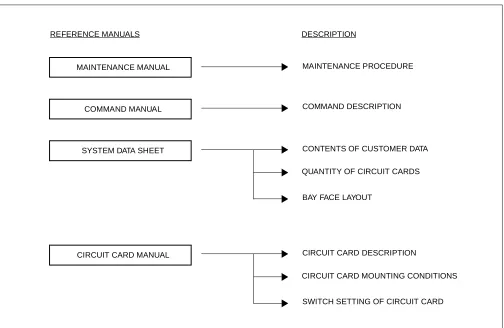
2. REFERENCE MANUAL
During installation, refer also to the manuals below:
Figure 1-1 Reference Manuals for Installation
CIRCUIT CARD MANUAL
COMMAND DESCRIPTION
CONTENTS OF CUSTOMER DATA MAINTENANCE PROCEDURE
QUANTITY OF CIRCUIT CARDS
BAY FACE LAYOUT MAINTENANCE MANUAL
REFERENCE MANUALS
COMMAND MANUAL
SYSTEM DATA SHEET
CIRCUIT CARD DESCRIPTION
CIRCUIT CARD MOUNTING CONDITIONS
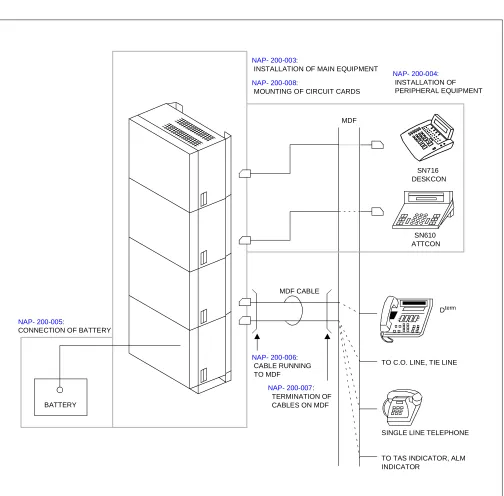
3.1 SCOPE OF INSTALLATION PROCEDURES
This manual covers the installation shown in Figure 1-2.
Figure 1-2 Scope of Installation Works
NAP- 200-003:
INSTALLATION OF MAIN EQUIPMENT NAP- 200-008:
MOUNTING OF CIRCUIT CARDS
NAP- 200-004: INSTALLATION OF PERIPHERAL EQUIPMENT
SN610 ATTCON MDF
MDF CABLE
NAP- 200-006: CABLE RUNNING TO MDF
NAP- 200-007: TERMINATION OF CABLES ON MDF
Dterm
TO C.O. LINE, TIE LINE
SINGLE LINE TELEPHONE
TO TAS INDICATOR, ALM INDICATOR
BATTERY NAP- 200-005:
CONNECTION OF BATTERY
ND-45492 (E) CHAPTER 2 Page 3 Revision 2.0
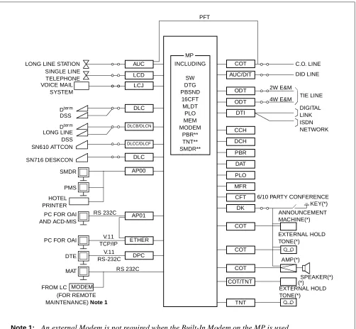
A typical trunking diagram for the PBX is shown in Figure 2-1.
Figure 2-1 PBX Trunking Diagram
MODEM
Note 1: An external Modem is not required when the Built-In Modem on the MP is used. Note 2: The equipment marked with (*) is provided by the customer.
Note 3: The MP functions marked with (**) are included in the PN-CP03 card only.
4W E&M 2W E&M RS 232C V.11 TCP/IP V.11 RS-232C RS 232C LONG LINE STATION
SINGLE LINE TELEPHONE VOICE MAIL SYSTEM Dterm DSS Dterm LONG LINE DSS SN610 ATTCON SMDR PMS HOTEL PRINTER
PC FOR OAI AND ACD-MIS
PC FOR OAI
DTE
MAT
FROM LC
(FOR REMOTE MAINTENANCE)Note 1
DPC ETHER AP01 AP00 DLCC/DLCF DLCB/DLCN DLC LCJ LCD AUC PFT MP INCLUDING SW DTG PBSND 16CFT MLDT PLO MEM MODEM PBR** TNT** SMDR** COT AUC/DIT ODT ODT DTI CCH DCH PBR DAT PLO MFR CFT DK COT COT COT COT/TNT TNT EXTERNAL HOLD TONE(*) (*)SPEAKER(*) AMP(*) EXTERNAL HOLD TONE(*) ANNOUNCEMENT MACHINE(*) KEY(*) 6/10 PARTY CONFERENCE
DIGITAL LINK ISDN NETWORK TIE LINE DID LINE C.O. LINE
Note : Refer to the Circuit Card Manual for details of circuit cards.
AP00 SMDR/Hotel Application Card LCD Line Circuit Card
(for Single Line Telephone)
AP01 OAI Interface Card LCI Line Circuit Card for Voice Mail
Integra-tor
AUC Analog Universal Circuit Card
(Long Line Circuit, DID Trunk)
MAT Maintenance Administration Terminal
BGM External Music Source for Dterm Back Ground Music Service
MDF Main Distribution Frame
CCH Common Channel Handler Card MEM Main Memory
CFT 6/10 party Conference Trunk Card MFR MF Receiver Trunk Card
COT C.O. Trunk Card MLDT Melody Trunk Card
DAT Digital Announcement Trunk Card MODEM Modem
DCH D-Channel Handler Card MP Main Processor Card
DIT DID Trunk Card PFT Power Failure Transfer
DK External Relay/Key Interface Card PMS Property Management System
DLC Digital Line Circuit Card (for Dterm/SN 716 DESKCON)
CDT OD Trunk Card (2/4 wire E&M)
DLCB/DLCN Digital Line Circuit Card (for Dterm Long Line/SN 716 DESKCON)
PBR PB Receiver Card
DLCC/DLCF Digital Line Circuit Card (for SN610 ATTCON)
PBSND PB Sender
DPC Data Port Controller Card PLO Phase Lock Oscillator
DSS DSS Console SMDR Station Message Detail Recording
DTI Digital Trunk Interface Card SW Time Division Switch
DTG Digital Tone Generator TNT Tone/Music Source Interface Card
ETHER Ethernet Control Card 16CFT 16 Circuit Three/Four Party Conference
Trunk
ND-45492 (E) CHAPTER 2 Page 5 Revision 2.0
• Wall-Mounting Installation
• 19-Inch Rack-Mounting Installation
• Desk Top Installation
This equipment can only be serviced by a qualified service person.
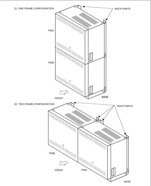
Examples of system configurations for each installation method are shown in Figure 2-2 through 2-7.
Figure 2-2 1-PIM Configuration for Floor Standing Installation RACK PARTS
PIM
Figure 2-3 2-PIM Configuration for Floor Standing Installation
BASE PIM1
PIM0
BASE
BASE RACK PARTS
PIM1 FRONT
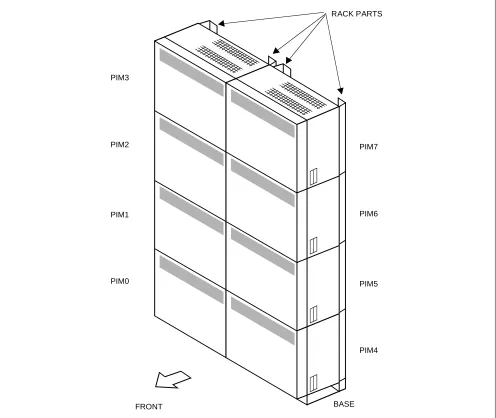
ND-45492 (E) CHAPTER 2 Page 7 Revision 2.0 Figure 2-4 8-PIM Configuration for Floor Standing Installation
PIM3
PIM2
PIM1
PIM0
PIM7
PIM6
PIM5
PIM4
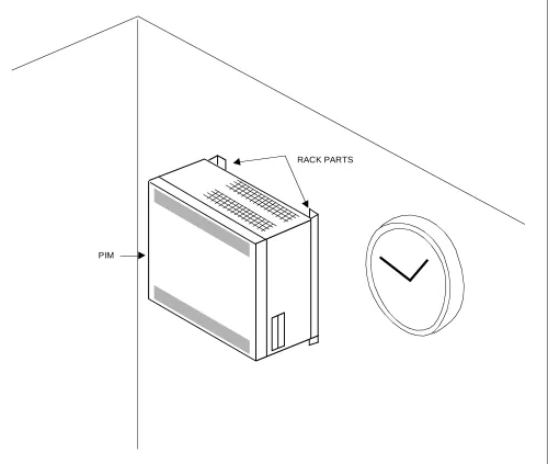
Figure 2-5 1-PIM Configuration for Wall-Mounting Installation
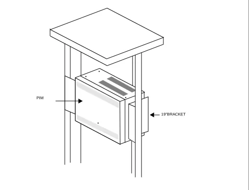
ND-45492 (E) CHAPTER 2 Page 9 Revision 2.0 Figure 2-6 1-PIM Configuration for 19-inch Rack-Mounting Installation
19”BRACKET
ND-45492 (E) CHAPTER 3 Page 11 Revision 2.0 1.1 GROUNDING REQUIREMENTS
The system grounding must have a specific ground resistance and AC noise level, and is to be connected to a pre-determined terminal in the NEAX2000 IVS. Standard grounding requirements are as shown below:
• Communication grounding : Less than 10 ohm
• Protective ground for PIM: Less than 10 ohm
Note: The AC ripple on these various grounds should be less than 0.5 Vp-p.
The following specific requirements apply to ground wiring.
1.1.1 EQUIPMENT GROUND
An equipment grounding conductor that is at least as large as the ungrounded branch-supply conductors is to be installed as part of the circuit that supplies the NEAX2000 IVS. Bare, covered, or insulated grounding conduc-tors are acceptable. Individually covered or insulated equipment grounding conducconduc-tors shall have a continuous outer finish that is either green, or green with one or more yellow stripes. The equipment grounding connector is to be connected to ground at the service equipment.
The attachment-plug receptacles in the vicinity of the NEAX2000 IVS are all to be of a grounding type, and the equipment grounding conductors serving these receptacles are to be connected to earth ground at the service equipment.
1.1.2 SUPPLEMENTARY GROUND
In addition to the equipment grounding conductor in the power supply cord, a supplementary equipment ground-ing conductor shall be installed between the product or system and ground. This conductor shall be at least as large as the ungrounded branch-supply conductors. It shall be connected to the NEAX2000 IVS at the terminal provided, and shall be connected to to ground in a manner that will retain the ground connection when the NEAX2000 IVS is unplugged from the receptacle.
The connection to ground of the supplementary equipment grounding conductor shall be in compliance with the rules for terminating bonding jumpers in Part K of Article 250 of the National Electrical Code, ANSI/NFPA 70. Termination of the supplementary equipment grounding conductor is permitted to be made to building steel, to a metal electrical raceway system, or to any grounded item that is permanently and reliably connected to the electrical service equipment ground.
Bare, covered, or insulated grounding conductors are acceptable. A covered or insulated grounding conductor shall have a continuous outer finish that is either green, or green with one or more yellow stripes.
CAUTION
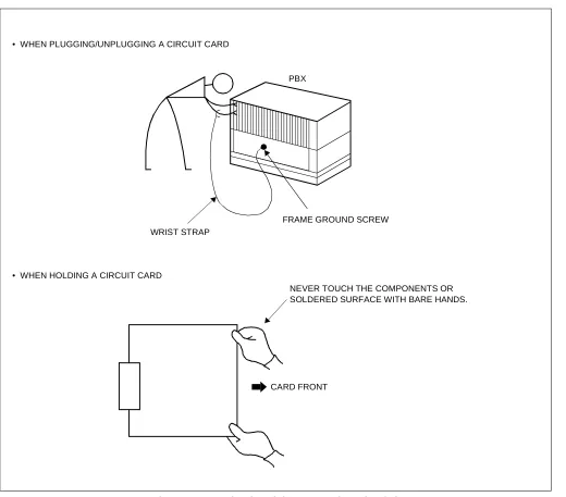
Figure 3-1 Static Electricity Precautions (1 of 2)
CARD FRONT PBX
WRIST STRAP • WHEN PLUGGING/UNPLUGGING A CIRCUIT CARD
• WHEN HOLDING A CIRCUIT CARD
FRAME GROUND SCREW
ND-45492 (E) CHAPTER 3 Page 13 Revision 2.0 Figure 3-1 Static Electricity Precautions (2 of 2)
WHEN CARRYING A CIRCUIT CARD AROUND, KEEP THE CARD IN A CONDUCTIVE POLYETHYLENE BAG. WEAR A WRIST STRAP AND PERFORM
THE WORK ON A GROUNDED CONDUCTIVE WORK SURFACE. CIRCUIT
CARD
CIRCUIT CARD
CONDUCTIVE POLYETHYLENE BAG
Table 3-1 Procedure for Unplugging/Plugging Circuit Cards
CIRCUIT CARD
PROCEDURE
CONDITION
PLUG UNPLUG
• SPN-CP00/CP03 (MP) • PZ-PW86 (PWR) • SPN-PW00 (PWR)
Power off
⇓
Plug in
⇓
Power on
Power off
⇓
Unplug
⇓
Power on
These circuit cards must be plugged in or unplugged only with power off to prevent damage to the card or other system circuitry.
• SPN-CP01 (FP) • SPN-CP02 (MP) • SPN-BS00 (BS00) • SPN-BS01 (BS01) • SPN-AP00 (AP00)
• SPN-ME00 (EXTMEM)
• SPN-24DTA (DTI) • SPN-SC00 (CCH) • SPN-SC01 (DCH) • SPN-SC02 (ICH) • SPN-CK00 (PLO) • SPN-4RSTB (MFR) • SPN-AP01 (AP01)
• SPN-VM00
Power off or MB switch on
⇓
Plug in
⇓
Power on or MB switch off
Power off or MB switch on
⇓
Unplug
⇓
Power on
These circuit cards must be plugged in or unplugged under Make Busy condition or power off to prevent damage to the card or other system circuitry.
ND-45492 (E) CHAPTER 3 Page 15 Revision 2.0
PBX
CARD FRONT
Figure 3-2 Procedure Flowchart (1 of 2)
START
UNPACKING
MARKING AND DRILLING
INSTALLATION OF MAIN EQUIPMENT
CONNECTION OF BATTERY
TERMINATION OF CABLES ON THE MDF
INSTALLATION OF
PERIPHERAL EQUIPMENT
CABLE RUNNING
SWITCH SETTING OF CIRCUIT CARDS
A
NAP- 200-001
NAP- 200-002
NAP- 200-003
NAP- 200-004
NAP- 200-005
NAP- 200-006
NAP- 200-007
ND-45492 (E) CHAPTER 3 Page 17 Revision 2.0 Figure 3-2 Procedure Flowchart (2 of 2)
The mark shown below is attached to the NAP sheet for each procedure in which circuit cards are handled. When doing such a procedure, the installer must perform the procedure with caution, to prevent damage caused by stat-ic electrstat-icity (See section 1.2, “Static Electricity Precautions” in this chapter).
END
MOUNTING OF THE FRONT COVER SYSYEM INITIALIZATION
AND
SYSTEM DATA ENTRY
OPERATION TEST
NAP- 200-010
NAP- 200-011
NAP- 200-012
CLEANING AND VISUAL CHECK
NAP- 200-013
INSTALLATION OF
BACK UP MP SYSTEM NAP- 200-009
TYPE OF SYSTEM Back up MP System
Single MP System
ATTENTION
Contents
Static Sensitive
Handling
1. Unpacking Procedure
(1) Check the received quantity of packages containing the NEAX2000 IVS system with the description on the shipping document.
(2) Check the packaging for external damage done by transportation and record it as necessary.
(3) Unpack the packaging.
• For unpacking the packages containing circuit cards, a grounded wrist strap should be worn.
(4) Check the quantity of equipment and materials unpacked with the shipping document.
(5) Perform visual inspection, checking for the following items.
Modules Overall distortion.
Scratches and dents on the surface.
Scratches and cracks on the PIM Backplane.
Broken or bent pins on the PIM Backplane.
Covers Scratches and dents.
Circuit Cards Overall distortion
Scratches and cracks
Loss, or damage of parts on the circuit cards.
Attendant Console Scratches and cracks on the keyboard
Overall distortion
Damage to keys and lamps.
Handling
ND-45492 (E) CHAPTER 3 Page 19 Revision 2.0 Figure 001-1 Unpacking of Main Equipment
RACK PARTS
ACCESSORIES
1. Confirmation of the Equipment Layout
Install the equipment in an area which provides adequate ventilation and is easily accessible to service person-nel.
2. Marking
2.1. Floor Standing
• Referring to Figure 002-1, mark the installation holes for the main equipment. • Mark the installation holes for the external MDF, if required.
Figure 002-1 Floor Marking for Main Equipment
356 mm (14.01 inch)
430 mm (16.93 inch)
FRONT RACK PARTS
WALL
39 mm (1.54 inch)
110 mm (4.33 inch)
35 mm (1.37 inch)
37 mm (1.46 inch)
356 mm (14.01 inch)
430 mm (16.93 inch)
FRONT RACK PARTS
37 mm (1.46 inch) 40 mm (1.57 inch)
184 mm (7.24 inch)
ND-45492 (E) CHAPTER 3 Page 21 Revision 2.0 2.2. Wall Mounting
• Locate and mark the wall mounting points as shown in Figure 002-2.
Figure 002-2 Wall Mounting Points
PIM
PIM
PIM
PIM
ANCHOR (x4/PIM)
430 mm (16.9 inch)
BASE
250 mm (9.8 inch)
350 mm (13.8 inch)
40 mm (1.6 inch) BASE BOTTOM POSITION PBX BOTTOM POSITION
PIM 390 mm
(15.4 inch)
430 mm (16.9 inch)
5 mm (0.2 inch) 382 mm
(15.0 inch)
350 mm (13.8 inch)
350 mm (13.8 inch)
350 mm (13.8 inch)
3. Drilling
• Drilling and installing anchor bolts
Figure 002-3 Instruction for Anchor Bolt
(4) (3)
(2) (1)
(1) DRILL A HOLE IN THE CONCRETE WITH A DRILL SUITABLE FOR A PLUG BOLT A LITTLE DEEPER THAN THE PLUG BOLT LENGTH.
(2) INSERT THE ANCHOR BOLT INTO THE HOLE.
(3) PUSH ANCHOR BOLT UNTIL THE BOLT STAYS PERMANENTLY IN PLACE.
ND-45492 (E) CHAPTER 3 Page 23 Revision 2.0
Install the main equipment according to the desired procedure for either Floor Standing, Wall-Mounting, 19-Inch Rack-Mounting or Desk Top installation.
1. Floor Standing Installation
(1) Connect the RACK PARTS to the rear side of the BASE with 4 bolts provided.
Figure 003-1 Connection of RACK PARTS and BASE
REAR
(2) In a Multiple-PIM Configuration
(a) When the system is a multiple-PIM configuration, connect the RACK PARTS to each other as shown
in Figure 003-2.
Figure 003-2 Connection of RACK PARTS
REAR
BASE RACK PARTS
ND-45492 (E) CHAPTER 3 Page 25 Revision 2.0
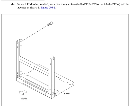
(b) For each PIM to be installed, install the 4 screws into the RACK PARTS on which the PIM(s) will be mounted as shown in Figure 003-3.
Figure 003-3 Installation of Screws onto RACK PARTS
REAR
(3) Attaching the BASE to the floor.
• Position the BASE over the holes drilled as per Figure 002-1.
• Secure the BASE to the floor using anchor bolts.
Figure 003-4 Securing of the BASE
FRONT BASE
INSTALLATION HOLE
ND-45492 (E) CHAPTER 3 Page 27 Revision 2.0
(4) Secure the PIM to the RACK PARTS as shown in Figure 003-5 by tightening the 4 screws already mounted in the RACK PARTS. When the system is a multiple-PIM configuration, secure all PIMs and RACK PARTS.
Figure 003-5 Connection of the PIM and the RACK PARTS
REAR
BASE
PIM
(5) Mount the PIM on the BASE, and connect them together using 3 bolts (provided). Refer to Figure 003-6.
Note: The PIM must be mounted over the 4 RACK PART screws previously installed in step 2(b).
Figure 003-6 Mounting of the PIM
FRONT
BASE
PIM Note
ND-45492 (E) CHAPTER 3 Page 29 Revision 2.0
(6) When the system is a multiple-PIM configuration, connect PIMs to each other with 3 bolts provided, as shown in Figure 003-7.
Note: Each PIM must be installed over the 4 RACK PART screws previously installed in step 2(b).
Figure 003-7 Connection of PIMs
PIM
PIM
(7) Position the TOP COVER on the top PIM, and connect them together with 4 screws (provided).
Figure 003-8 Mounting of the TOP COVER
FRONT
PIM
ND-45492 (E) CHAPTER 3
Addendum-001 Page 31
JANUARY, 1999 Revision 2.1
(8) The cable connections on the PZ-PW86 card are shown in Figure 003-9.
(a) PZ-PW86 (A)
Figure 003-9 Cable Connection on the PZ-PW86 (1 of 3)
PZ-PW86(A)
MJ MN ON BATTERY MODE SWITCH
GND Note FG –27V
PWR CNT CA-A
PWR CA-A
BATTERY CABLE/PWR CA-A TO PWR1
TO OTHER
AC CORD-A TO AC MAINS INPUT TO POWER OUTPUT
POWER OUTPUT
TO PWR0A CONNECTOR TO PWR0B CONNECTOR CABLE (+5V, –27V,E)
CABLE (CR, E)
CONNECTOR
PZ-PW86 TO AUXILIARY
BATTERY CONNECTOR (BATT2)
ON OFF
100/120V
240V EQUIPMENT
TO BATTERY OR OTHER PZ-PW86 GREEN WHITE BLACK AC CORD-B OR
(FOR 1-PIM SYSTEMS)
TO THE TERMINAL BLOCK AT BASE (FOR MULTIPLE PIM SYSTEMS)
FRAME GROUND TERMINAL ON THE CHASSIS Set the appropriate voltage before turning on the SW switch.
CAUTION
Note: If GND (Signal GND) has to be separated from FG (Frame GND), remove the link between GND and FG terminals.
1: NO CONNECTION 2: ON: OPEN/FLOAT 1
OFF: SEAL/FLOAT 2
– O
BATTERY CONNECTOR (BATT1) 1
2 ON
(FOR 1-PIM SYSTEMS)
(b) PZ-PW86 (C)
Figure 003-9 Cable Connection on the PZ-PW86 (2 of 3)
PZ-PW86(C)
MJ MN ON BATTERY MODE SWITCH
GND Note 2 FG
–27V
PWR CNT CA-A
PWR CA-A
BATTERY CABLE/PWR CA-A TO PWR1
TO OTHER
AC CORD-A
TO AC MAINS INPUT TO POWER OUTPUT
POWER OUTPUT
TO PWR0A CONNECTOR TO PWR0B CONNECTOR CABLE (+5V, –27V,E)
CABLE (CR, E)
CONNECTOR
PZ-PW86 TO AUXILIARY
BATTERY CONNECTOR (BATT2)
ON OFF
100/120V
240V EQUIPMENT
TO BATTERY OR OTHER PZ-PW86 GREEN WHITE BLACK AC CORD-B OR
(FOR 1-PIM SYSTEMS)
TO THE TERMINAL BLOCK AT BASE (FOR MULTIPLE PIM SYSTEMS)
FRAME GROUND TERMINAL ON THE CHASSIS Set the appropriate voltage before turning on the SW switch.
CAUTION
Note 1: Follow the Label on Front Plate of the PZ-PW86(C).
Note 2: If GND (Signal GND) has to be separated from FG (Frame GND), remove the link between GND and FG terminals.
1: NO CONNECTION
OFF: OPEN/FLOAT 1 2: ON: SEAL/FLOAT 2
– O
BATTERY CONNECTOR (BATT1) 1
2 ON
(FOR 1-PIM SYSTEMS)
L N NOMINAL AC INPUT TO TERMINAL MARKED: ON BASE (See Figure 003-11)
Note 1
TO PWR0D CONNECTOR
ND-45492 (E) CHAPTER 3
Addendum-001 Page 33
JANUARY, 1999 Revision 2.1
(c) PZ-PW86 (D)
Figure 003-9 Cable Connection on the PZ-PW86 (3 of 3)
PZ-PW86(D)
MJ MN ON BATTERY MODE SWITCH
GND Note 2 FG
–27V
PWR CNT CA-A TO PWR1
AC CORD-A
TO AC MAINS INPUT TO POWER OUTPUT
POWER OUTPUT
TO PWR0A CONNECTOR TO PWR0B CONNECTOR CABLE (+5V, –27V,E)
CABLE (CR, E)
CONNECTOR TO AUXILIARY
BATTERY CONNECTOR (BATT2)
ON OFF 100/120V 240V EQUIPMENT GREEN WHITE BLACK AC CORD-B OR
(FOR 1-PIM SYSTEMS)
TO THE TERMINAL BLOCK AT BASE (FOR MULTIPLE PIM SYSTEMS)
FRAME GROUND
Note 1: Follow the Label on Front Plate of PZ-PW86(D).
Note 2: If GND (Signal GND) has to be sep-arated from FG (Frame GND), re-move the link between GND and FG terminal.
1: NO CONNECTION
OFF: OPEN/FLOAT 1 2: ON: SEAL/FLOAT 2
– O 1
2 ON
TERMINAL ON THE
(See Figure 003-11)
Note 1
TO PWR0D CONNECTOR
POWER OUTPUT CABLE (+90V,E)
TO OTHER PZ-PW86
PWR CA-A
TO BATTERY OR OTHER PZ-PW86
BATTERY CONNECTOR (BATT1) BATTERY CABLE/PWR CA-A
CHASSIS (FOR 1-PIM SYSTEMS)
L N NOMINAL AC INPUT TO TERMINAL MARKED: ON BASE Set the appropriate voltage before turning on the SW switch.
(9) Confirm the connection of the PWR CNT CA-A and power output cables as shown in Figure 003-10 (These cables are pre-installed).
Figure 003-10 Cable Connection between the PZ-PW86 and the BWB
LTC CONNECTOR AREA
PIM
BWB (Back Wiring Board)
PZ-PW86
PWR0B PWR0A RS
PWR1
PWR CNT CA-A
POWER OUTPUT CABLE (CR,E)
ND-45492 (E) CHAPTER 3 Page 35 Revision 2.0
(10) AC CORD-B and AC Power Cable Wiring
(a) The AC CORD-B and the AC Power Cable Wiring to the FG, NEUTRAL and LINE terminals inside the BASE are shown in Figure 003-11 (for details of wiring to the terminals, see Figure 003-12).
Figure 003-11 AC CORD-B and AC Power Cable Wiring
TO GROUND TERMINAL
FRONT SEE FIGURE 003-12
AC CORD-B
3P AC POWER CABLE PIM
PIM
(b) Secure the AC CORD-B cables to the FG, NEUTRAL and LINE terminals as shown in Figure 003-12. The 3P AC Power Cable and the FG Cable are pre-installed with the BASE.
Figure 003-12 Screwing the AC CORD-B to the Terminals
FG
NEUTRAL
LINE BASE
3P AC POWER CABLE TO 120/240 V AC SOURCE POWER AC POWER
KNOCK OUT HOLE
(PROVIDED WITH BASE) FG CABLE
(PROVIDED WITH BASE)
PIM AC CORD-B
TO PZ-PW86 IN PIM (PROVIDED WITH PIM) PUSH
PULL
: INSERT THE AC CORD : FIXED THE AC CORD
CORD BUSH
(PROVIDED WITH BASE)
ND-45492 (E) CHAPTER 3 Page 37 Revision 2.0
(c) When the system is a two-frame configuration, the 3P AC Power Cable of the left side frame can go through the BASE of the right side frame, as shown in Figure 003-12.
Figure 003-13 AC Power Cable Wiring for Two-Frame Configuration
FG NEUTRAL LINE FG NEUTRAL LINE
3P AC POWER CABLE
TO 120/240 V AC SOURCE POWER SUPPLEMENTARY GROUND
(11) When the system is a multiple-PIM configuration, connect the PZ-PW86 Cards to each other using PWR CA-A cables, as shown in Figure 003-14 and Figure 003-15.
Figure 003-14 PWR CA-A
550mm (21.7 inch)
ND-45492 (E) CHAPTER 3 Page 39 Revision 2.0
(a) When using an External Battery or the BATTM
Figure 003-15 Connection of PWR CA-A Cables (1 of 2)
PIM7
PIM6
PIM5
PIM4 PIM3
PIM2
PIM1
PIM0
PWR CA-A
PZ-PW86
BATT2
BATT1
PZ-PW86
BATT2
BATT1
PZ-PW86
BATT2
BATT1
PZ-PW86
BATT2
BATT1
TO BATTERY
PZ-PW86
BATT2
BATT1
PZ-PW86
BATT2
BATT1
PZ-PW86
BATT2
BATT1
PZ-PW86
BATT2
BATT1
TO BATTERY PWR CA-A
Note: For details of battery connection, see NAP- 200-005.
PWR CA-A
PWR CA-A
PWR CA-A
(b) When using an Internal Battery
Figure 003-15 Connection of PWR CA-A Cables (2 of 2)
PIM7
PIM6
PIM5
PIM4 PIM3
PIM2
PIM1
PIM0
PZ-PW86
BATT2
BATT1
PZ-PW86
BATT2
BATT1
PZ-PW86
BATT2
BATT1
PZ-PW86
BATT2
BATT1
PZ-PW86
BATT2
BATT1
PZ-PW86
BATT2
BATT1
PZ-PW86
BATT2
BATT1
PZ-PW86
BATT2
BATT1 TO BATTERY
PWR CA-A
TO BATTERY
TO BATTERY
PWR CA-A
TO BATTERY TO BATTERY
PWR CA-A
TO BATTERY
TO BATTERY
PWR CA-A
TO BATTERY
ND-45492 (E) CHAPTER 3 Page 41 Revision 2.0
(12) When the system is a multiple-PIM configuration, mount the PN-BS00 Card in the BUS slot of PIM0. Also, mount the PN-BS01 Card in each BUS slot of PIM1 through PIM7.
When the system is a single PIM configuration, neither PN-BS00 nor PN-BS01 is needed.
Figure 003-16 Mounting of the BUS Cards
B S 0 1
B S 0 1
B S 0 1
B S 0 0
B S 0 1
B S 0 1
B S 0 1
B S 0 1 PIM3
PIM2
PIM1
PIM0
PIM7
PIM6
PIM5
(13) When the system is a multiple-PIM configuration, connect all the BUS Cards (PN-BS00/PN-BS01) to each other using BUS cables, as shown in Figure 003-17 and Figure 003-18.
Figure 003-17 BUS Cable
700mm (27.6 inch)
ND-45492 (E) CHAPTER 3 Page 43 Revision 2.0 Figure 003-18 Connection of the BUS Cables
PIM7
PIM6
PIM5
PIM4 PIM3
PIM2
PIM1
PIM0
BS01
CN2
CN1
CN2
CN1
CN2
CN1
CN2
CN1
BS01
CN2
CN1
CN2
CN1
CN2
CN1
CN2
CN1
48-TW-0.7 CONN CA BS01
BS01
BS00
BS01
BS01
(14) When the system is a multiple-rack configuration, connect the PN-BS00 in rack 1 to the PN-BS00 in rack using BUS cable, as shown in Figure 003-19 and Figure 003-20.
Figure 003-19 BUS Cable
1 meter (39 inches)
ND-45492 (E) CHAPTER 3 Page 45 Revision 2.0 Figure 003-20 Connection of the BUS Cables
PIM7
PIM6
PIM5
PIM4 PIM3
PIM2
PIM1
PIM0
BS01
CN2
CN1
CN2
CN1
CN2
CN1
CN2
CN1
BS01
CN2
CN1
CN2
CN1
CN2
CN1
CN2
CN1
48-TW-1 CONN CA BS01
BS01
BS00
BS01
BS01
BS01 48-TW-.07
CONN CA
2. Wall Mounting Installation
(1) Using four appropriate fasteners (locally provided; see Table 003-1) for the type of wall construction, se-cure the RACK PARTS as shown in Figure 003-21. For the wall mounting points, refer to Figure 002-2 in NAP-200-002.
Note: For the wall-mounting installation, a concrete wall is recommended because the concrete wall is more firm to mount the PBX than a wooden wall or a plaster board. The plaster board is the most infirm wall of the three.
Table 003-1 Recommended Fasteners
WALL TYPE RECOMMENDED FASTENER
PLASTER BOARD [THICKNESS Min. 9.6 mm (0.38 inch)]
MOLLY ANCHOR TYPE Min. 3.5 mm (0.14 inch) DIA. Max. 4.5 mm (0.17 inch) DIA
WOOD WOOD TYPE SCREWS Min. 3.5 mm (0.14 inch) DIA
Max. 4.5 mm (0.17 inch) DIA
CONCRETE ANCHOR BOLT TYPE Recommended 4 mm (0.16 inch) by
ND-45492 (E) CHAPTER 3 Page 47 Revision 2.0 Figure 003-21 Screwing the RACK PARTS to a Wall
350 mm (13.8 inch)
350 mm (13.8 inch) 250 mm
(9.8 inch)
ANCHOR (x4/PIM) (SEE FIGURE 002-2) (WALL)
382 mm (15.0 inch) M4 MACHINE SCREW-B (x4/PIM)
SECURED TO RACK PARTS (PROVIDED WITH RACK PARTS)
SCREW-A (x4/PIM)
SECURING RACK PARTS TO WALL (LOCALLY PROVIDED)
(SEE TABLE 003-1)
M5 MACHINE SCREW-C (x4/PIM) (PROVIDED WITH RACK PARTS) (SEE FIGURE 003-20)
(2) When mounting the RACK PARTS to a wall, connect all the RACK PARTS to each other, and connect the
BASE to the bottom RACK PARTS using the M5 Machine screws (provided), as shown in Figure 003-21.
Figure 003-22 Connecting the RACK PARTS and the BASE
(JOINT)
RACK PARTS
M5 MACHINE SCREW-C (x2/JOINT AREA)
(PROVIDED WITH RACK PARTS)
(JOINT)
ND-45492 (E) CHAPTER 3 Page 49 Revision 2.0
(3) Attach four M4 machine screws (provided) to the RACK PARTS as shown in Figure 003-21.
For proper mounting of each PIM, approximately 4 mm (0.2 inch) spacing should be provided between the inner face of the M4 machine screw and the RACK PARTS front channel. See Figure 003-23.
(4) Align and insert the key hole slots of the rear cover of each PIM to the machine screws secured in step (3).
See Figure 003-23.
Figure 003-23 Mounting the PIM to the RACK PARTS
(PIM)
APPROX. 4 mm (0.2 inch)
(WALL)
SCREW-A (x 4)
RACK PARTS M4 MACHINE SCREW-B (x 4)
(REAR COVER)
(LOCALLY PROVIDED)
(5) After hanging each PIM onto the RACK PARTS, tighten each M4 machine screw using a Phillips screw driver as shown in Figure 003-24.
Figure 003-24 Screwing the PIM to the RACK PARTS
M4 MACHINE SCREW-B (X4)
ND-45492 (E) CHAPTER 3 Page 51 Revision 2.0
(6) Connect the bottom PIM and the BASE, and connect PIMs to each other using 3 bolts (provided), as shown
in Figure 003-6 and Figure 003-7. Then, position the TOP COVER on the top PIM and connect them
to-gether with 4 screws (provided), as shown in Figure 003-8.
(7) Connect the AC CORD-B to the terminals inside the BASE in the same manner as for the Floor Standing Installation (Refer to Figure 003-11 through Figure 003-13).
(8) When the system is a multiple-PIM configuration, connect the PZ-PW86 cards to each other using PWR CA-A cables (Refer to Figure 003-14 through Figure 003-15).
(9) When the system is a multiple-PIM configuration, mount the PN-BS00 card in the BUS slot of PIM0, and mount the PN-BS01 card in each BUS slot of PIM1 through PIM7 (Refer to Figure 003-16).
Then, connect all the BUS cards (PN-BS00/PN-BS01) to each other using BUS cables (Refer to Figure
3. 19-Inch Rack-Mounting Installation 3.1. Single-PIM Installation
(1) Before mounting the PIM, connect the TOP COVER, BOTTOM COVER and AC CORD-A to the PIM as
shown in Figure 003-25. The AC CORD-A is pre-installed with the BOTTOM COVER.
Figure 003-25 Connecting the Covers and AC CORD-A to the PIM
TOP COVER
TO PZ-PW86 PIM
AC CORD-A
BOTTOM COVER LOCAL CABLE DUCT
ND-45492 (E) CHAPTER 3 Page 53 Revision 2.0
(2) Secure the 19” BRACKET to the 19-inch Rack as shown in Figure 003-26 .
(3) Mount the PIM on the 19” BRACKET as shown in Figure 003-26 .
Then, secure the PIM to the 19” BRACKET as shown in Figure 003-26 .
Figure 003-26 Mounting the PIM to the 19-Inch Rack (1 of 2)
A
B C
A B
PIM 19” BRACKET
C
FRONT
19” BRACKET
19-INCH RACK
3.2. Multiple-PIM Installation
(1) Secure the 19” BRACKET to the 19-inch Rack as shown in Figure 003-26 .
(2) Mount a PIM on the 19” BRACKET as shown in Figure 003-26 .
Then, secure the PIM to the 19” BRACKET as shown in Figure 003-26 .
(3) Repeat step (1) and (2) according to the number of modules. A maximum of 5 modules (4 PIMs and 1 MD-FM) can be mounted in the 19-inch Rack.
Figure 003-26 Mounting the PIM to the 19-Inch Rack (2 of 2)
A
B C
A B
PIM 19” BRACKET
C
FRONT
19” BRACKET
19-INCH RACK
Note: The MDFM can be installed in the same manner as the PIM.
ND-45492 (E) CHAPTER 3 Page 55 Revision 2.0
(4) Position the TOP COVER on the top PIM, and connect them with 4 screws (provided) as shown in Figure
003-27.
Figure 003-27 Mounting of the TOP COVER
FRONT
TOP COVER
19" BRACKET
(5) Connect the BASE to the bottom PIM as shown in Figure 003-28.
Figure 003-28 Connecting the BASE to the PIM Note: The MDFM can be connected to the BASE in the same manner as the PIM.
FRONT
BASE BASE
PIM
19" BRACKET
19" BRACKET
ND-45492 (E) CHAPTER 3 Page 57 Revision 2.0
(6) Do the following cable connectons in the same manner as for Floor Standing Installation.
(a) Connect the AC CORD-B cables to the terminals inside the BASE (Refer to Figure 003-11 through
Figure 003-13).
(b) Connect the PZ-PW86 cards to each other using PWR CA-A cables (Refer to Figure 003-14 through
Figure 003-15).
(c) Mount the PN-BS00 card in the BUS slot of PIM0, and mount the PN-BS01 card in each BUS slot of PIM1 through PIM3 (Refer to Figure 003-16).
Then, connect all the BUS cards (PN-BS00/PN-BS01) to each other using BUS cables (Figure
4. Desk Top Installation
(1) Connect the TOP COVER, BOTTOM COVER and AC CORD-A to the PIM as shown in Figure 003-29.
The AC CORD-A is pre-installed with the BOTTOM COVER.
Figure 003-29 Connecting the Covers and AC CORD-A to the PIM
TOP COVER
TO PZ-PW86 PIM
AC CORD-A
BOTTOM COVER LOCAL CABLE DUCT
ND-45492 (E) CHAPTER 3 Page 59 Revision 2.0
(2) Connect the RUBBER FEET to the PIM as shown in Figure 003-30.
Figure 003-30 Connecting the RUBBER FOOT to the PIM
BOTTOM PIM
RUBBER FOOT
PIN
1. Installation of External MDF
• Secure the external MDF onto the floor or mount the MDF onto the wall.
• Mount the required MDF components.
• If required, install the cable ducts for the cables to be laid between the MDF and the Main Equipment. In this case, confirm the locations of the cable holes for the Main Equipment. Refer to Figure 004-1.
Figure 004-1 Location of the Cable Hole
FRONT
430 mm (16.9 inch) RACK PARTS
214 mm (8.4 inch)
ND-45492 (E) CHAPTER 3 Page 61 Revision 2.0 2. Installation of SN610 ATTCON
(1) Screw the handset support onto the bottom of the console as shown in Figure 004-2.
Figure 004-2 Mounting of the Handset Support to the SN610 ATTCON
Handling
Precautions Required
HANDSET SUPPORT
(2) To provide the console with the headset in place of the handset, unplug the modular cord from the handset and plug the modular cord to the Jack Set.
Figure 004-3 Jack Set Installation for the SN610 ATTCON
Handling
Precautions Required
SN610 ATTCON
MODULAR CORD
ND-45492 (E) CHAPTER 3 Page 63 Revision 2.0
(3) Set the switch located inside the console according to the type of headset/handset connected. Refer to
Fig-ure 004-4.
Figure 004-4 Switch Setting on the SN610 ATTCON (1 of 2)
Handling
Precautions Required
• Slide the directory out of the way.
Then insert a flat screw driver’s blade into the notched opening and apply light upward pressure until the access panel is clear of the front lip. At the same time apply pressure (toward you) at the rear of the pedestal to move the access panel.
ACCESS PANEL
Figure 004-4 Switch Setting on the SN610/611/615 ATTCON (2 of 2)
Handling
Precautions Required
D
S
C SWITCH
• Set the switch according to the type of headset/handset connected.
C: Carbon Type Handset/Headset
S: SUPRA Headset
D: Dterm Type Handset
ND-45492 (E) CHAPTER 3 Page 65 Revision 2.0
(4) Plug the line cord into the modular jack located at the bottom of the console. For the MDF cross connection
for the SN610 ATTCON, refer to NAP- 200-007 (Figure 007-23).
Figure 004-5 Cable Connection to the SN610 ATTCON
Handling
Precautions Required
LINE CORD
PBX
PN-2DLCC 2P
MDF MODULAR
TERMINAL
SN610 ATTCON
3. Installation of SN716 DESKCON
(1) Screw the handset support onto the bottom of the console, if required.
Figure 004-6 Mounting of the Handset Support to the SN716 DESKCON
The handset support bracket is reversible to mount on either side of the SN716 DeskCon. To mount the sup-port unit on the right hand side of the DeskCon, reverse the mounting bracket on the handset supsup-port unit (two screws). Then attach the handset support with three screws on the right side of the DeskCon.
Handling
ND-45492 (E) CHAPTER 3 Page 67 Revision 2.0
(2) Plug the headset into the modular jack (H/S 0 or H/S 1) located at the bottom of the console, if required.
Figure 004-7 Headset Installation for the SN716 DESKCON
Handling
Precautions Required
(3) Plug the line cord into the modular jack (LINE) located at the bottom of the console. For the MDF cross connection fot the SN716 DESKCON, refer to NAP-200-007 (Figure 007-24, 007-24).
Figure 004-8 Cable Connection to the SN716 DESKCON
Handling
Precautions Required
PBX
DLC 1P
MDF MODULAR
TERMINAL
SN716 DESKCON
3P 3P
PW00 2P
LINE CORD
ND-45492 (E) CHAPTER 3 Page 69 Revision 2.0
(4) When using an AC-DC ADAPTER for power supply, plug the AC-DC ADAPTER into the “12V~24VDC” terminal located at the rear of the console. This adapter is the same as the Dterm Series E AC-DC adapter.
Figure 004-9 AC-DC ADAPTER Connection to the SN716 DESKCON
Handling
Precautions Required
AC/DC ADAPTER
(5) When using the PW00 card for power supply, provide the PW00 card according to the following procedure.
(a) Mount the PW00 card into the LT01-LT15 or AP6 slot.
Figure 004-10 Mounting PW00 Card into PIM
Handling
Precautions Required
BUILT-IN BATTERY
ND-45492 (E) CHAPTER 3 Page 71 Revision 2.0
(b) Connect the PW00 card and SN716 DESKCON using installation cable as shown in Figure 004-11
and Figure 007-24 (1 of 1 and 1 of 2).
Figure 004-11 PW00 Card connection to the SN716 DESKCON
Handling
Precautions Required
PIM
PWR0C
CONN Connector PW00
TO DESKCON
PWR1
1. Battery Connection
WARNING:Turn off AC power before connecting batteries.
Recommended Battery
Internal Battery: YUASA
MATSUSHITA
type NPH-3.2-12 type LCR-12V3.4NE
External Battery: (BATTM)
YUASA MATSUSHITA
type NP-24-12B type LCL-12V-24
If battery terminals (+, –) contact with the module while connecting the battery cable to the PZ-PW86 card, the PZ-PW86 card or the BWB may be shorted. Therefore, the installer must perform work in accordance with the following steps when mounting or removing the batteries.
(1) When mounting batteries:
(a) Connect the battery cable to the batteries.
(b) Mount the batteries into the appointed position of the PIM or the BATTM.
(c) Connect the battery cable to the PZ-PW86 card.
(2) When removing batteries:
(a) Disconnect the battery cable from the PZ-PW86 card.
(b) Remove the batteries from the PIM or the BATTM.
ND-45492 (E) CHAPTER 3 Page 73 Revision 2.0 CAUTION
Battery Replacement Table and Battery Warnings
The label which shows battery replacement table and battery warnings is attached to the reverse side of Front Cover for PIM and BATTM.
During the battery installation process, the warning statements must be observed. When replacing batteries, the battery replacement table should be observed to increase battery life and ensure a safe operation.
• ELECTROLYTE LEAKAGE OR OTHER HAZARDS MAY RE-SULT IF THE BATTERY IS NOT REPLACED IN ACCOR-DANCE WITH THE SPECIFIED INTERVALS.
AMBIENT TEMPERATURE
25°C (77°F)
25°C ~ 30°C (77°F ~ 86°F)
30°C ~ 40°C (86°F ~ 104°F)
REPLACEMENT INTERVAL
2.5 ~ 3 YEARS
2.0 ~ 2.5 YEARS
1.5 ~ 2.0 YEARS
FRONT COVER PIM/BATTM
LABEL
TO PREVENT INJURY AND SKIN BURN, PAY ATTENTION TO THE FOLLOWING.
• DO NOT STRIKE A MATCH OR CAUSE A SPARK IN VI-CINITY OF BATTERY.
• PLACE THE EQUIPMENT IN A WELL VENTILATED AR-EA.
• DO NOT SHORT.
• REPLACE BATTERY ONLY AFTER BATTERY GASES HAVE BEEN DISPERSED.
CAUTION
BATTERY REPLACEMENT TABLE
1.1. Internal Battery Connection
(1) Install the two batteries (12VDC, 3.0-3.4AH) into each PIM as shown in Figure 005-1.
Figure 005-1 Internal Battery Mounting
FRONT 67mm
DIMENSION OF BATTERY BATTERY UNIT
(2 × 12VDC, 3.0 to 3.4AH)
(2.6 inch)
134mm (5.3 inch) 60mm
(2.4 inch)
BASE PIM PIM
ND-45492 (E) CHAPTER 3 Page 75 Revision 2.0
(2) Plug the battery cable connector into the BATT1 connector on the PZ-PW86 as shown in Figure 005-2.
(3) Secure the batteries and battery cable using tie wraps as shown in Figure 005-2.
Figure 005-2 Internal Battery Connection
PLUG IN TO BATT 1 CONNECTOR ON PZ-PW86
FRONT
TIE WRAP BASE
(4) When the system is a multiple PIM configuration, provide the following connections to the internal batter-ies.
Figure 005-3 Internal Battery Connection for a Multiple PIM Configuration
BATT2
BATT1 PZ-PW86
– +
– +
PIM3
BATT2
BATT1 PZ-PW86
– +
– +
PIM2
BATT2
BATT1 PZ-PW86
– +
– +
PIM1
BATT2
BATT1 PZ-PW86
– +
– +
PIM0
BATTERY CABLE
BATT2
BATT1 PZ-PW86
– +
– +
PIM7
BATT2
BATT1 PZ-PW86
– +
– +
PIM6
BATT2
BATT1 PZ-PW86
– +
– +
PIM5
BATT2
BATT1 PZ-PW86
– +
– +
PIM4
BATTERY CABLE Blue