Available online: https://edupediapublications.org/journals/index.php/IJR/ P a g e | 2357
Intensification of Grid Power by Utilizing PV or Wind STATCOM in
Transmission Lines
BOLISHETTI RAVITEJA ROSAIAH MUDIGONDLA
PG Scholar, Dept of EEE (EPS) Assistant Professor, Head of Dept (EEE)
Arjun College of Technology & Science Arjun College of Technology & Science
Hayathnagar (M ), R.R. District, TS, India Hayathnagar (M ), R.R. District, TS, India
………
ABSTRACT
The main aim of project is a novel concept of utilizing a photovoltaic (PV) solar farm inverter as STATCOM, called PV-STATCOM, for improving stable power transfer limits of the interconnected transmission system. The entire inverter rating of the PV solar farm, which remains dormant during nighttime, is utilized with voltage and damping controls to enhance stable power transmission limits. During daytime, the inverter capacity left after real power production is used to accomplish the aforementioned objective. Transient stability studies are conducted on a realistic single machine infinite bus power system having a midpoint located PV-STATCOM using simulation software. Power transfer increases are also demonstrated in the same power system for: 1) two solar farms operating as PV-STATCOMs and 2) a solar farm as PV-STATCOM and an inverter-based wind farm with similar STATCOM controls. This novel utilization of a PV solar farm asset can thus improve power transmission limits which would have otherwise required expensive additional equipment, such as series/shunt capacitors or separate flexible ac transmission system controllers.
Index terms: PV-STATCOM, Solar farm, Power quality, Wind system,
1.INTRODUCTION
Available online: https://edupediapublications.org/journals/index.php/IJR/ P a g e | 2358 night and the remainder inverter capacity after real power generation during the day, both of which remain unused in conventional solar farm operation. Similar STATCOM control functionality can also be implemented in inverter-based wind turbine generators during no-wind or partial wind scenarios for improving the transient stability of the system. Studies are performed for two variants of a single-machine infinite bus (SMIB) system. One SMIB system uses only a single PV solar farm as PV-STATCOM connected at the midpoint whereas the other system uses a combination of a PV-STATCOM and another PV-STATCOM or an inverter-based wind distributed generator (DG) with similar STATCOM functionality. Three-phase fault studies are conducted using the electromagnetic transient software EMTDC/PSCAD, and the improvement in the stable power transmission limit is investigated for different combinations of STATCOM controllers on the solar and wind farm inverters, both during night and day.
2.PHOTOVOLTAIC TECHNOLOGY
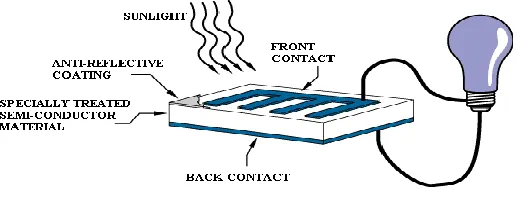
Photovoltaic’s is the field of technology and research related to the devices which directly convert sunlight into electricity using semiconductors that exhibit the photovoltaic effect. Photovoltaic effect involves the creation of voltage in a material upon exposure to electromagnetic radiation.
The photovoltaic effect was first noted by a French physicist, Edmund Becquerel, in 1839, who found that certain materials would produce small amounts of electric current when exposed to light. In 1905, Albert Einstein described the nature of light and the photoelectric effect on which photovoltaic technology is based, for which he later won a Nobel prize in physics. The first photovoltaic module was built by Bell Laboratories in 1954. It was billed as a solar battery and was mostly just a curiosity as it was too expensive to gain widespread use. In the 1960s, the space industry began to make the first serious use of the technology to provide power aboard spacecraft. Through the space programs, the technology advanced, its reliability was established, and the cost began to decline. During the energy crisis in the 1970s, photovoltaic technology gained recognition as a source of power for non-space applications.
The solar cell is the elementary building block of the photovoltaic technology. Solar cells are made of semiconductor materials, such as silicon. One of the properties of semiconductors that makes them most useful is that their conductivity may easily be modified by introducing impurities into their crystal lattice. For instance, in the fabrication of a photovoltaic solar cell, silicon, which has four valence electrons, is treated to increase its conductivity. On one side of the cell, the impurities, which are phosphorus atoms with five valence electrons (n-donor), donate weakly bound valence electrons to the silicon material, creating excess negative charge carriers.
Available online: https://edupediapublications.org/journals/index.php/IJR/ P a g e | 2359 However, the diffusion of carriers does not occur indefinitely, because the imbalance of charge immediately on either sides of the junction originates an electric field. This electric field forms a diode that promotes current to flow in only one direction.
Ohmic metal-semiconductor contacts are made to both the n-type and p-type sides of the solar cell, and the electrodes are ready to be connected to an external load. When photons of light fall on the cell, they transfer their energy to the charge carriers. The electric field across the junction separates photo-generated positive charge carriers (holes) from their negative counterpart (electrons). In this way an electrical current is extracted once the circuit is closed on an external load.
Fig 1: Solar cell.
The photovoltaic effect was first reported by Edmund Becquerel in 1839 when he observed that the action of light on a silver coated platinum electrode immersed in electrolyte produced an electric current. Forty years later the first solid state photovoltaic devices were constructed by workers investigating the recently discovered photoconductivity of selenium. In 1876 William Adams and Richard Day found that a photocurrent could be produced in a sample of selenium when contacted by two heated platinum contacts. The photovoltaic action of the selenium differed from its photoconductive action in that a current was produced spontaneously by the action of light.
No external power supply was needed. In this early photovoltaic device, a rectifying junction had been formed between the semiconductor and the metal contact. In 1894, Charles Fritts prepared what was probably the first large area solar cell by pressing a layer of selenium between gold and another metal.
3. STATCOM
Available online: https://edupediapublications.org/journals/index.php/IJR/ P a g e | 2360
The advantage of a STATCOM is that the reactive power provision is independent from the actual voltage on the connection point. This can be seen in the diagram for the maximum currents being independent of the voltage in comparison to the SVC. This means, that even during most severe contingencies, the STATCOM keeps its full capability.
In the distributed energy sector the usage of Voltage Source Converters for grid interconnection is common practice today. The next step in STATCOM development is the combination with energy storages on the DC-side. The performance for power quality and balanced network operation can be improved much more with the combination of active and reactive power.
STATCOMs are based on Voltage Sourced Converter (VSC) topology and utilize either Gate-Turn-off Thyristors (GTO) or Isolated Gate Bipolar Transistors (IGBT) devices. The STATCOM is a very fast acting, electronic equivalent of a synchronous condenser. If the STATCOM voltage, Vs, (which is proportional to the dc bus voltage Vc) is larger than bus voltage, Es, then leading or capacitive VARS are produced. If Vs is smaller then Es then lagging or inductive VARS are produced.
Fig.2pulses statcom.
The three phases STATCOM makes use of the fact that on a three phase, fundamental frequency, steady state basis, and the instantaneous power entering a purely reactive device must be zero. The reactive power in each phase is supplied by circulating the instantaneous real power between the phases. This is achieved by firing the GTO/diode switches in a manner that maintains the phase difference between the ac bus voltage ES and the STATCOM generated voltage VS. Ideally it is possible to construct a device based on circulating instantaneous power which has no energy storage device (ie no dc capacitor.
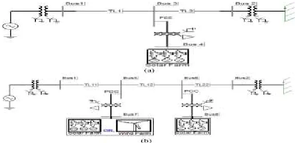
Available online: https://edupediapublications.org/journals/index.php/IJR/ P a g e | 2361 The single-line diagrams of two study systems: Study System 1 and Study System 2 are depicted in Fig.
Fig3. Single-line diagram of (a) study system I with a single solar farm (DG) and (b) study system II with a solar farm (DG) and a solar/wind farm (DG).
respectively. Both systems are single-machine infinite bus (SMIB) systems where a large equivalent synchronous generator (1110 MVA) supplies power to the infinite bus over a 200-km, 400-kV transmission line. This line length is typical of a long line carrying bulk power in Ontario. In Study System 1, a 100-MW PV solar farm (DG) as STATCOM (PV-STATCOM) is connected at the midpoint of the transmission line. In Study System 2, two 100-MVA inverter-based distributed generators (DGs) are connected at 1/3 (bus 5) and 2/3 (bus 6) of the line
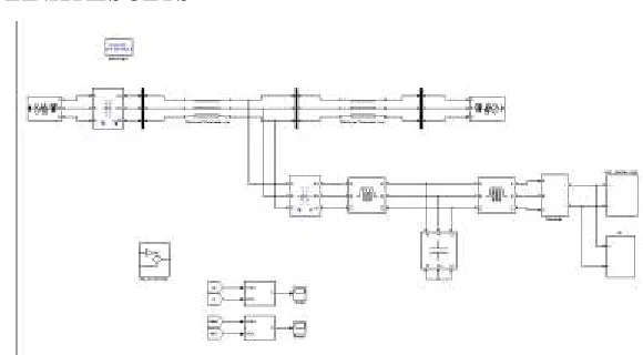
Available online: https://edupediapublications.org/journals/index.php/IJR/ P a g e | 2362 Fig4. Complete DG (solar/wind) system model with a damping controller and PCC voltage -control
system.
5. REACTIVE POWER CONTROL
The conventional reactive power control only regulates the reactive power output of the inverter such that it can perform unity power factor operation along with dc-link voltage control.The switching signals for the inverter switching are generated through two current control loops in - -0 coordinate system.The inverter operates in a conventional controller mode only provided that “Switch-2” is in the “OFF” position. In this simulation, the voltage vector is aligned with the quadrature axis, that is, 0,hence, is only proportional to which sets the reference for the upper control loop involving PI1. Meanwhile, the quadrature axis component is used for dc-link voltage control through two PI controllers (PI-2 and PI-3) shown in Fig. according to the set point voltage provided by the MPPT and and injects all available real power “P” to the network.To generate the proper IGBT switching signals (gt1, gt2, gt3, gt4, gt5, gt6), the – components ( and ) of the modulating signal are converted into three-phase sinusoidal modulating signals and compared with a high-frequency (5-kHz) fixed magnitude triangular wave or carrier signal.
Damping Control
A novel auxiliary damping controller is added to the PV control system and shown in Fig.5.2. (b). This controller utilizes line current magnitude as the control signal. The output of this controller is added with the signal . The transfer function of this damping controller is expressed as in
Available online: https://edupediapublications.org/journals/index.php/IJR/ P a g e | 2363 the damping control design studies. This power level is considered equal to the transient stability limit of the system with the solar farm being disconnected at night. At this operating power level, if a three-phase fault occurs at Bus 1, the generator power oscillations decay with a damping ratio of 5%. The solar farm is now connected and operated in the PV-STATCOM mode.
MATLAB/SIMULINK RESULTS
Fig 5. MATLAB/SIMULINK Diagram of Complete DG (solar/wind) system mo del with a damping controller an d PCC v o ltag e -co n tro l s y s tem.
Fig 6 p v s u b s y s tem
Available online: https://edupediapublications.org/journals/index.php/IJR/ P a g e | 2364
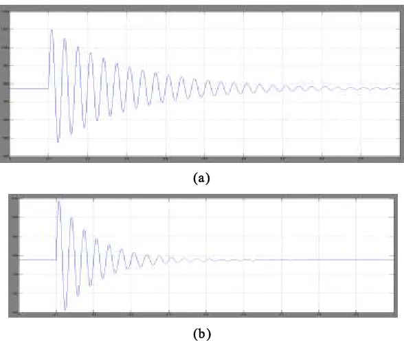
(a)
(b )
Fig 8 Nig h t time (a) g en erato r p o wer Pg (B) in fin ite b u s p o wer Pin f
(a)
(b )
Available online: https://edupediapublications.org/journals/index.php/IJR/ P a g e | 2365
CONCLUSION
A novel patent-pending control paradigm of PV solar farms is presented where they can operate during the night as a STATCOM with full inverter capacity and during the day with inverter capacity remaining after real power generation, for providing significant improvements in the power transfer limits of transmission systems [31], [32]. This new control of PV solar system as STATCOM is called PV-STATCOM. The effectiveness of the proposed controls is demonstrated on two study SMIB systems: System I has one 100-MW PV-STATCOM and System II has one 100-MW PV-STATCOM and another 100-MW PV-STATCOM or 100-MW wind farm controlled as STATCOM. Three different types of STATCOM controls are proposed for the PV solar DG and inverter-based wind DG. These are pure voltage control, pure damping control, and a combination of voltage control and damping control. This study thus makes a strong case for relaxing the present grid codes to allow selected inverter-based renewable generators (solar and wind) to exercise damping control, thereby increasing much needed power transmission capability. Such novel controls on PV solar DGs (and inverter-based wind DGs) will potentially reduce the need for investments in additional expensive devices, such as series/shunt capacitors and FACTS. The PV-STATCOM operation opens up a new opportunity for PV solar DGs to earn revenues in the nighttime and daytime in addition to that from the sale of real power during the day. This will, of course, require appropriate agreements between the regulators, network utilities, solar farm developers, and inverter manufacturers.
REFERENCES
[1] R. M. Mathur and R. K. Varma, Thyristor-Based FACTS Controllers for Electrical Transmission Systems. Hoboken, NJ, USA: Wiley/IEEE, 2002.
[2] S. A. Rahman, R. K. Varma, and W. Litzenberger, “Bibliography of FACTS applications for grid integration of wind and PV solar power systems: 1995–2010, IEEE working group report,” presented at the IEEE Power Energy Soc. Gen. Meeting, Detroit, MI, USA, Jul. 2011.
[3] Y. Xiao, Y. H. Song, C.-C. Liu, and Y. Z. Sun, “Available transfer capability enhancement using FACTS devices,” IEEE Trans. Power Syst., vol. 18, no. 1, pp. 305–312, Feb. 2003.
[4] Cross Texas Transmission, Salt fork to gray project. 2014. [Online]. Available: http://www.crosstexas.com/SFWind.htm
[5] R. K. Varma, V. Khadkikar, and R. Seethapathy, “Nighttime application of PV solar farm as STATCOM to regulate grid voltage,” IEEE Trans. Energy Convers., vol. 24, no. 4, pp. 983–985, Dec. 2009.
[6] R. K. Varma and V. Khadkikar, “Utilization of solar farm inverter as STATCOM,” U.S. Provisional Patent, Sep. 15, 2009.
[7] R. K. Varma, S. A. Rahman, and R. Seethapathy, “Novel control of grid connected photovoltaic (PV) solar farm for improving transient stability and transmission limits both during night and day,” in Proc. World Energy Conf., Montreal, QC, Canada, 2010, pp. 1–6.
Available online: https://edupediapublications.org/journals/index.php/IJR/ P a g e | 2366 [9] F. L. Albuquerque, A. J. Moraes, G. C. Guimaraes, S. M. R. Sanhueza, and A. R. Vaz, “Photovoltaic solar system connected to the electric power grid operating as active power generator and reactive power compensator,” Solar Energy, vol. 84, no. 7, pp. 1310–1317, Jul. 2010.