R E S E A R C H
Open Access
Coherent query scheme for wireless
backscatter communication systems with
single tag
Aminolah Hasanvand
1, Ali Khaleghi
1,2,3*and Ilangko Balasingham
2Abstract
An un-coded multi-transmitter query scheme is introduced for wireless backscatter communication systems in which M transmitters and N receivers are used for single-tag connectivity (M× 1 ×N). The main idea is to harden the wireless communication channel with a tag device for high data rate readings. The proposed method is designed for multipath fading channels in which the backscatter channel is a multiplicative Rayleigh. A coherent transmit query scheme is used to increase the tag-reflected signals and simultaneously alter the fading statistics in the forward path by implementing a receiver feedback. Full-diversity performance and array gain is achieved using the receiver diversity without requiring any tag antenna diversity. Therefore, the tag device remains simple. Mathematical expressions for the probability density function (PDF) of the backscatter channel are presented using closed-form equations. Bit error rate (BER) simulations for the binary phase shift keying (BPSK) modulation are computed numerically. Diversity gain of 10 dB is obtained by using a 2 × 1 × 1 scheme. The results show that the transmit diversity for single-tag usage performs the same as the tag antenna diversity, at the expense of a moderate transmitter complexity. The tag device remains intact as a requirement for the simplicity and size
constraints. Also, the system realization becomes more feasible due to the available space on the transmitter side to accomplish the uncorrelated forward channel conditions. The feasibility study is demonstrated using software-defined radio (SDR) implementations.
Keywords:Backscatter communication, Transmit diversity, Antenna diversity, Wireless communication, Bit error rate, Backscatter channel feedback
1 Introduction
Radio frequency identification (RFID) is known in the commercial sectors. Passive or semi-passive tag devices are used in RFID to modulate the radiated RF carrier signals in the wave propagation channel, in which the reader can demodulate the tag’s specific data [1]. The wireless com-munication approach avoids using an active transmitter in the tag device for power and space savings. By including a sensory data source in the tag device, real-time sensing and data transmission become feasible for applications in the wireless sensor network (WSN) [2–4]. An innovative implementation is for data-intensive applications such as
video streaming using the semi-passive devices. The importance is that the power associated with the transmit-ter task can be eliminated from the tag device. This permits cost, space, and power saving for semi-passive devices for guaranteed longevity with the available power resources. It is also possible to use the ambient signals from radio stations for the backscatter communications; the ambient signals are used to illuminate the tag device instead of the reader’s transmitter [5–7]. Considering high data rate communication for data-intensive applications, we target hardening the communication channel with a semi-passive tag device in the multipath fading channels.
Backscatter communication is a radar approach that is different from one-way wireless communication in which the wave propagation channel observes two distinct paths. In the forward path, the RF carrier is emitted from the transmitter and has no information. In the return path, * Correspondence:[email protected]
1K. N. Toosi University of Technology (KNTU), Tehran, Iran
2Norwegian University of Science and Technology (NTNU), Trondheim,
Norway
Full list of author information is available at the end of the article
the tag device modulates the tag’s antenna impedance that appeared as a variable radar cross section (RCS) [8]. The backward channel includes the tag-specific information in the form of amplitude or phase modulation of the radiated carrier. The remote receiver decodes the tag antenna re-flections and extracts the tag’s data [9]. The modulation level is determined by the number of the loads used in the tag device for switching among [10]. Thus, ultra-low power tag becomes feasible thanks to using an ultra-low power switch device instead of an active transmitter with the power-hungry frontend. The communication link per-formance can be calculated using Radar equations.
One specific environment for the backscatter application is an indoor quasi-stationary channel. The channel can be modeled as a slow fading multipath environment. By as-suming the modulation bandwidth, which is the tag an-tenna switching speed, less than the coherence bandwidth of the backward channel, the frequency selectivity of the channel is neglected. Thus, a Rayleigh channel in the for-ward and backfor-ward paths is realized for the non-line of sight (NLOS) scenarios. Considering independent channels in the forward and backward links, which can be attained by separating the transmitter and the receiver antennas within a distance more than the spatial correlation of the channel, the cascade channel becomes a multiplication of two independent Rayleigh channels. The equivalent chan-nel is no longer Rayleigh [11], and it observes deeper fading conditions. To establish a reliable link, the statistics of the multiplicative Rayleigh channel should be positively altered in a way to convert it back to a Rayleigh or Gaussian channel. Thus, the channel can be hardened for high data rate connectivity. Antenna diversity is a practical approach that can be implemented in the data path, i.e., tag or receiver antenna diversity [12,13].
1.1 Related works
The application of antenna diversity in the receiver side has been demonstrated [14,15]. The diversity gain is mar-ginal because the forward channel is always Rayleigh, and the overall channel is the multiplication of Rayleigh and diversity combined channel. Tag antenna diversity has been proposed to combat fading in the forward channel [16]. The requirement is that the tag antennas should be physically spaced with large distances, more than the spatial correlation of the channel. The minimum distance for uncorrelated channels depends on the wave angle of arrivals (AoAs) and is about half a wavelength for uni-formly distributed AoAs. The correlation distance is larger if this condition cannot be attained. Therefore, full diver-sity gain fails to achieve in a compact tag device despite the simple structure. Further, using multiple tag antennas requires multiple and synchronous electronic switch circuits to alter the antenna impedances simultaneously over all the antennas that complicate the tag system.
Using multiple transmitters does not influence the statis-tics of the multiplicative channels [11,17,18], because the underlying assumption is that the transmitter is not the in-formation source. The only achievement with using mul-tiple transmitter schemes is a reduced spatial correlation distance by increasing the AoAs. The multi-transmitting effect in backscatter communication has been studied in [19, 20] as a unitary query method of transmission with tag-specific space-time coding (STC). This method is a breakthrough and provides a significant gain by using time diversity in the forward channel besides the spatial diversity (STC coding) in the backward channel and outperforms the uniform query method of transmission. The drawback is the increased tag complexity and power consumption in addition to the sophisticated transmitter scheme that should be operated in a synchronous manner with the tag device for improved performance. Another form of the multi-transmitting scheme is conducted in [21,22], where multi-sin transmitting scheme (frequency diversity) is used to transfer more power to the tag device to achieve better performance in the reading range.
1.2 Motivation and contributions
In this paper, we propose an un-coded transmit diversity
scheme using a minor feedback from the receiver to
improve the BER (bit error rate) performance and increase the communication range by altering the overall channel statistics. We call it “minor” because only the received signal strength is used to establish coherency in the query transmitters. The receiver feedback is feasible because the transceivers are closely located, and the received signal strength can be accessed and used in the transmitter for optimal system operation. The proposed transmit diversity performs the same as tag antenna diversity [11], but with a single-tag antenna. The system performance is better than the unitary query method of transmission [19] without added complexity in the tag device. Our approach is optimum for single-tag usage. Furthermore, it can provide time reversal spatial focusing at the tag location for a targeted data reading. The main contributions of this paper are as follows:
– Transmit diversity with equal gain combining (EGC)
is proposed at the query end with channel feedback of one receiver for intended tag connectivity. It is shown that the probability density function (PDF) and BER performances can be improved significantly with the main complexity at the reader side.
– Demonstration of the transmitter query scheme is shown using software defined radio
implementations.
1.3 Organization
The paper is organized as follows. In Section 2, the mathematical expressions for the statistics of the back-scatter communication channel are presented. The ana-lytical expressions for the statistics of the proposed transmit query scheme with feedback channel are calcu-lated in Section3. Numerical simulation results for BER performance of the transmit query for BPSK modulation are given in Section 4. Experimental validation of the approach for single-channel implementation using a software-defined radio (SDR) is given in Section 5. In Section6, the receiver diversity is added to the proposed backscatter system in which we show that the feedback from one receiver is sufficient to achieve full-diversity performance. Section8concludes this paper.
2 Backscatter communications
Any multiple input multiple output (MIMO) backscat-ter communication system consists of three operational parts: query end, tag end, and receiving end [19].
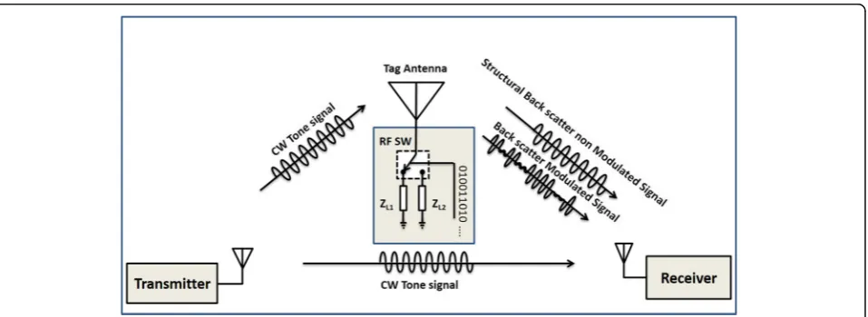
Fig-ure 1 shows the scheme of a backscatter
communica-tion system in a single-tag scenario. An unmodulated continues wave (CW) signal is transmitted in the wave propagation channel. The signal paths that experience tag reflections carry tag-specific data. The signal paths that do not experience the tag device are considered as stationary interference. At the receiving end, the inter-ference signal is removed and the signal demodulation is conducted. The backscatter channel can be inter-preted as a pinhole channel [23], and the only differ-ence is that the data is generated at the tag (pinhole) instead of the transmitter.
A nominal backscatter communication setup uses a single-transmitter antenna and multiple receiver antennas, or it can include multiple antennas in the tag device. Using multiple transmitter antennas does not influence the communication system performance [11,17,24].
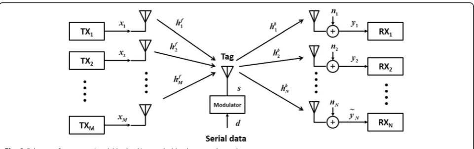
Consider a M× 1 ×N backscatter communication
system with M transmitters in the query end, single-tag antenna and N receivers are shown in
Fig. 2. Assume that the modulation bandwidth
gen-erated by the tag switching is less than the coher-ence bandwidth of the backward channel. Thus, the frequency selectivity of the channel is disregarded, and inter-symbol interference (ISI) is neglected. Therefore, the channel model in the forward and backward paths is expressed as Rayleigh. As shown
in Fig. 2, the transmitted carrier signals are
expressed as X, the forward channel is defined by Hf in which hif ¼jhif jej∠hif∈ℂ are the channel coeffi-cients. Superposition of these signals in the tag
an-tenna is modulated by the tag data signal s (exp.
s∈{−1, 1}for BPSK modulation). The backward
chan-nel, Hb, is expressed by its coefficients, hbi ¼jhbi
jej∠hb
i∈ℂ. The received signal is corrupted by the
noise N (ni¼jnijej∠ni∈ℂ) at the i-th receiver. The transmitted signals might be received at the re-ceivers without experiencing the tag path. The addition of these direct coupling signals is considered as a sta-tionary interference. Considering the narrowband signal-ing in the multipath channel, the channel becomes flat fading, and the received signal is expressed as:
YN1¼X1MHMf1HNb1SþNN1þDN1 ð1Þ
whereDis the direct coupling and
x¼½x1 x2…xM ; xi ¼Aiejφi;i¼1;2;…;M
The termDN × 1can be eliminated after signal demodu-lation by applying proper filtering for removing the stationary signals. This term consists of a tag structural radar cross section (RCS) and environment clutters that do not include the tag’s information [8, 25]. For a sta-tionary channel,DN × 1 appeared as a DC component in the demodulator and a simple high-pass filter can re-move it.
By considering the constant and equally distributed transmission power for the query end, i.e., jxij¼Ai
¼ 1ffiffiffiffi
where Kis a deterministic scalar coefficient including the filtering gain, transmitting signal amplitude, and other gains and^niis the color Gaussian noise.
For a single antenna in transmission, i.e., 1 ×1 × N, the received signal statistics at the i-th receiver is pro-portional to the production of two complex i.i.d Gauss-ian variablesh1fandhbias follows,
yi¼K h1f ejφ1
hb
isþ^ni∝h1f hbi ð3Þ
Thus, the envelope of the received signal has PDF of two Rayleigh products.
Considering the M transmitters, i.e., M× 1 ×N, the superposition of the carriers at the tag antenna are mod-ulated and then reflected in the channel. Therefore, the received signal is written as
yi∝
For flat fading channels with i.i.d. complex Gaussian property, the linear combination of M channels is i.i.d. complex Gaussian variable. The envelope of these channels is Rayleigh, and the received signal in thei-th receiver has PDF of two Rayleigh products [26]. There-fore, the above multi-transmitter system has no improvement compared to a single-transmitter scheme [17].
3 Multi-antenna transmission with channel feedback
Under the condition that the transmitter signals are coherently summed at the tag antenna, the maximum amount of the backscatter signal is achieved at the receiver. We show how this combination alters the channel statistics. For this purpose, the forward channel must be maximized at the tag’s position. Consequently, the overall gain of the forward channel should be maximized,
To obtain the condition above, the transmitters must be synchronized with a single reference clock (see Fig. 3).
Also, it is necessary to alter the phase of each trans-mitter to achieve the co-phase summation (maximize the amplitude of the received signal) at the tag loca-tion. Therefore, applying the condition in (5) to (4) results to
As a result, from (6), the PDF of the received signal envelope is the sum of M Rayleigh products. The signals terminated to the tag in the forward and backward chan-nels may be correlated. The amount of the correlation, ρ, depends on the distance between the transmitter and the receiver antennas.
The elements of the forward and backscatter links can be written in the Cartesian form, respectively, ashf =uf+jvf and hb=ub+jvb where uf, b and vf, b are zero-mean Gaussian random variables,Nð0;σ2f;b=2Þ,
in which σ2
f and σ2b are the variance of hkf andhbi ,
respectively. The envelope PDF of M× 1 ×N cascaded
backscatter channel is derived from that of the product of two Rayleigh random variables. The closed-form PDF for dependent and independent Rayleigh products is given in [26]. Therefore, by considering random vari-able Z as the multiplication of jhkf jand jhbi j, i.e., Z
¼jhkf j jhb
i j, its closed-form PDF is expressed as [26]:
where I0is a zero-order, modified Bessel function of the first kind andK0is a zero-order, modified Bessel function of the second kind. The characteristic function, Φ(.), of the sum of i.i.d. random variables, R¼PMk¼1jhkf‖hbi j (the inter parentheses of (6) that is envelop of the received signal in i-th receiver), is the product of their individual characteristic functions (CF), and consequently, their joint PDF can be derived by using the inverse Hankel trans-form. The CF (7) is found using Hankel transform [27], which was raised to the power of M to yield the CF for the cascaded backscatter channel ofM× 1 × 1 system:
Φðω;ρÞ ¼σ
By using the inverse Hankel transform on (8), the PDF ofM× 1 × 1 channel is derivable. However, it is difficult to solve its related integral analytically. Therefore, two special cases are considered forρ= 0, in whichhkfandhbiare inde-pendent, andρ= 1, where they are completely correlated.
The former case can be achieved by separating the re-ceiver and the transmitter which is known as bistatic top-ology. The latter is known as monostatic topology where the receiver and transmitter are co-located. The analytical calculations of the PDF for bistatic and monostatic models as upper and lower limits of dependency of the forward and the backward channels are conducted. Considering the bistatic topology (ρ= 0) the CF becomes
Φðω;0Þ ¼ σ
2 bσ2f
4 ω
2þ1
" #−M
ð9Þ
Applying the inverse Hankel transform to (9) yields the PDF ofM× 1 × 1 topology as
frðr;ρ¼0Þ ¼rM σ2 bσf
1þM 21−M
Γð ÞM Kð1−MÞ 2r
σbσf
ð10Þ
where K(1−M)(.) is the modified Bessel function of the order of (1−M) and the second kind,Γ(.), is the gamma function andris the channel envelope.
By considering the monostatic topology (ρ= 1), the CF is derived as
Φðω;ρÞ ¼ σ2
bσ2fω2þ1
h i−M
2 ð11Þ
Applying the inverse Hankel transform to (11) yields the PDF ofM× 1 × 1 topology as
frðr;ρ¼1Þ ¼r M
2 1 σbσf
1þM2 21−M2
ΓM.2K 1−M2
r
σbσf
ð12Þ
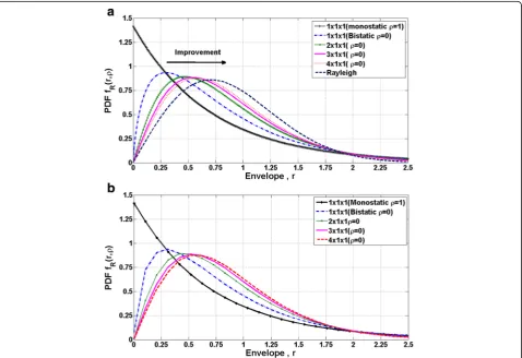
The PDF of the envelope of the channel at the n-th receiver antenna based on the above analytical expres-sions is plotted in Fig.4a.
Monte-Carlo channel realizations are provided to
compute the PDF numerically. For this purpose, 106
realizations are conducted, and the PDF of the envelope is obtained for the bistatic and monostatic topologies for
M× 1 × 1 (M= 1, 2, 3, 4). Figure4bshows the numerical
simulation results. As shown, the results of the simu-lation and the above analytical calcusimu-lations are in complete agreement. The PDF of a conventional one-way Rayleigh fading channel is also illustrated. We note that the PDF’s are normalized to unit trans-mit power. Deep fading in the PDF of the cascaded
backscatter channel can be seen in Fig. 4 compared
to the one-way Rayleigh channel, as it is shown from the left to right arrow. By increasing the number of the transmit antennas, the corresponding envelope PDF shifts to the right indicating reduced fading probability. The most significant change is seen in the transition from a fully correlated channel, where the PDF changes from an exponential distribution of the monostatic channel to a product of Rayleigh distribu-tion for the bistatic channel with M transmitters. By
increasing M, the PDF curves approach the Rayleigh distribution, in which a Rayleigh fading can express the cascade channel for massive numbers of coherent transmitters.
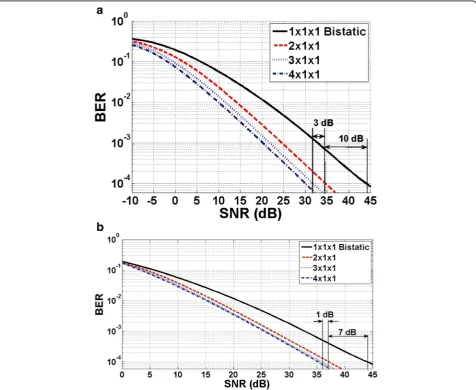
The backscatter communication performance is sim-ulated by assuming BPSK modulation with additive white Gaussian noise (AWGN). Coherent detection is used to evaluate BER performance. The number of the random channel realizations is 106 to achieve the en-semble average of BER. In the simulations with M transmitter antennas, the total power is normalized to
unity. Figure 5a shows the calculated BER versus SNR
(dB). As shown, by increasing the number of transmit antennas and by applying the phase compensation at the transmitter side, given in (10), the BER curves shift toward the left side of the graph. For instance, by
applying two transmitter antennas, we can observe a gain of 10 dB for BER level 10−4compared to a single antenna in transmission. The gain increases for M= 3 and 4. The improvement in BER performance can be described by the transmit array gain and the modifica-tion of the channel statistics as stated in (6) and Fig.4.
Figure5bshows the BER performance for the scenario in which the effective isotropic-radiated power (EIRP) is normalized to the unity. Therefore, the array gain is re-moved in BER calculations, and the improvement caused by the transmit diversity is obtained. As shown, a gain of 7 dB is achieved for BER level of 10−4due to the changes in the channel statistics. The rest of the 3 dB gain in Fig.5a
is related to the antenna array gain in transmission. In an ultimate scenario, with massive numbers of antennas in the forward channel, the overall channel statistics approaches Rayleigh performance for (M× 1 × 1,M➔∞).
4 Performance analysis by numerical simulations
The implementation of the proposed transmit diversity is simple. As a result from (5), for a co-phase signal combination at the tag location, the transmitters’ phase (φi,i= 1, 2,…, M) must be adjusted. Figure 3shows the
co-phase multi-transmit backscatter communication scheme. In this implementation, all the transmitters should have common reference clock, and a feedback from one receiver is used for the phase tuning. In the phase tuning process, one of the transmitters sends con-tinues wave (CW) signal in the channel. The tag reflects its data in the backscatter channel, and the reflections are received and demodulated by the receiver system. The signal level at the receiver is monitored. The sec-ond transmitter starts the operation by transmitting CW signal, and the phase of the transmitted carrier is
swept in the range [−π, π] to obtain the maximum
data signal at the receiver side. This process is similar to the phasor summation of the wave vectors. The pro-cedure is continued for the consequent transmitters,
and the phase tuning is performed for the newly added transmitter. Therefore, a relative phase among the transmitters are selected that increase SNR at the receiver. The proposed co-phasing algorithm is a simple approach, and it may be replaced by other fast and more adaptive algorithms which are not consid-ered in this work.
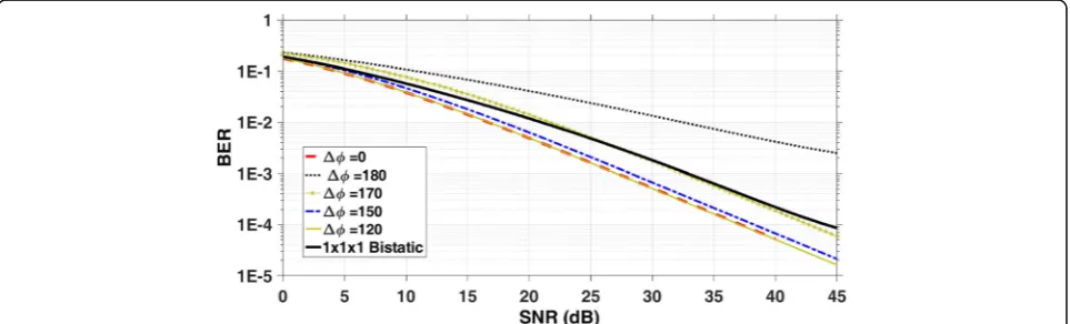
According to the approach above, the phase of each transmitter must be tuned to add SNR in the receiver. Therefore, the sensitivity of the scheme relative to the phase deviation among the transmitters is studied. Figure6
shows the simulated average BER performance for 2 × 1 × 1 backscatter channel with independent forward and backward Rayleigh fading channels. As shown, the phase deviation of 0° provides the best BER performance, in which the two transmitter signals are coherently added at the tag location. By the phase deviation from the optimal value, the performance is degraded. However, the per-formance is almost intact for the phase deviations up to 120°. The reason is the vector summation of the complex Gaussian random variables. From 120° to 170°, the formance is degraded rapidly in which the system per-formance is similar to a single antenna in transmission (see Fig.6). In case that the phase error lies in the range of 170°–180°, the system performance is worse than the sin-gle antenna configuration. In this case, the signals at the tag are destructive. Therefore, the probability to worsen the performance with dual antenna compared to the sin-gle antenna in transmission is about 10/180 or 5.5%. This result shows that if the second transmitter comes to the operation, with a random phase value, there is a probabil-ity of 5.5% that the system performance is degraded. How-ever, with the phase sweeping, the system performance can be improved for a wide range of phase values for in-stance 66% (i.e., 120/180). Therefore, the most essential characteristic of co-phase multi-transmit in backscatter communication is its low sensitivity to the phase deviation from the optimal value.
5 Experimental results
Demonstration of multi-transmitting coherent query scheme for backscatter communication is conducted using the experimental setup shown in Fig. 7. The plan of the indoor environment is illustrated in Fig. 7a. The transmitter antennas are log-periodic and the tag an-tenna is a circular patch on a ground plane with resonance frequency at 2.5 GHz (Fig. 7b,c). The tag antenna port is connected to an RF switchboard which is controlled by the data source from a computer program. The tag reflection is maximized by self-grounding the antenna (resonance mode) and is minimized by open circuit condition.
The transmitter antennas are located in one corridor and transmit CW signal at 2.5 GHz. To generate NLOS
conditions, the tag antenna is placed in the second corridor to remove the possible direct path from the transmitters. Two transmitters and one receiver are used for wireless communication with the semi-passive tag device. The transceivers are realized using software-defined radio (SDR), USRP N210. Two SDR transmitters are synchro-nized by using an external clock source Octoclock-G (Fig. 8d). Therefore, the relative phase of the transmitter carriers can be tuned via the system’s software program. One of the SDRs is also used as the receiver. MATLAB Simulink is used to implement the baseband processing functions. All SDRs are connected to their host PCs
through Giga Ethernet ensuring enough baseband
bandwidth.
The tag switch is controlled by the data from a PC which transfers the content of an image data in a defined protocol. All the requirements for data extraction in the receiver side are considered in this protocol.
In the experiment, we consider constant net power in the query ends. Thus, in the dual transmitter scheme, the transmitted power for each radio is re-duced by 3 dB compared to the single transmitter. Figure 8 shows the block diagram of the realized 2 × 1 × 1 backscatter communication system using USRP N210 and the related MATLAB Simulink target. The transmitter part can be tuned to operate in a defined carrier frequency. The gain of the transmitters can be
adjusted independently. In addition, a phase shifter is used that can modify the relative phase of the synchronized transmitters. The receiver includes auto-matic gain control (AGC), receiver match filter, coarse and fine frequency compensator, clock
recov-ery, and data decoding blocks. Figure 9a shows the
baseband received signal detected by the SDR
receiver; the eye diagram for both in-phase and
quadrature components is shown in Fig. 9b. The
overall system reads the transmitted image data via the backscatter link.
To demonstrate the applicability of the coherent query scheme, the detected backscatter signal level by
Fig. 9Experimental received signalaBaseband received signal after removing the direct coupling termbeye diagram after clock recovery for I & Q channels
the SDR receiver is used as the basis for the
perform-ance evaluation (Fig. 9a). MATLAB Simulink is used
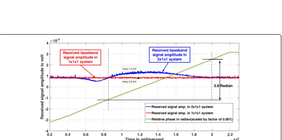
for the real-time monitoring of the tag data in the re-ceiver. First, one SDR transmitter with constant power is applied. Figure 10 shows the level of the de-tected signal for one-transmitter query system in the quasi-static channel. Using a two-transmitter scheme, by assigning half of the power to each transmitter, the received signal is detected. By sweeping the phase of one transmitter in the range [−π, π] with 5° steps per second, we can observe the received signal as the blue curve. As shown, the detected backscatter signal level is increased from 0.8 to 1.4 mv which is about 5 dB in terms of the received signal power. Also, for 60% of the phase interval, the baseband signal amplitude using 2 × 1 × 1 scheme is above the 1 × 1 × 1 scheme and confirms the simulation results in Section 4.
The reason for the improved signal level at the receiver is EM wave focusing in the forward path. To assess this fact, a spectrum analyzer is connected to the tag antenna port, and the received signal level is monitored by sweeping the transmitter phase. By monitoring the received carrier signal power at the tag antenna, it is observed that the transmitted signals with the above defined optimum phase values are coherently summed at the tag antenna location.
6 Receiver diversity
Receiver diversity is applied to further improve the BER performance by altering the channel statistics in
the backward path. For this purpose, we use
M-transmit and N-receive antennas. In the implemen-tation procedure, feedback from one receiver is ap-plied to the transmitter chain and the phase tuning task is completed to assure the coherent summation of the forwarding paths at the tag location. Thus, the transmit diversity task is completed. The receiver
diversity is applied to coherently combine the data signals in the receivers. To determine the amount of the improvement, Monte-Carlo simulations is con-ducted for 106 channel realizations, and EGC is used
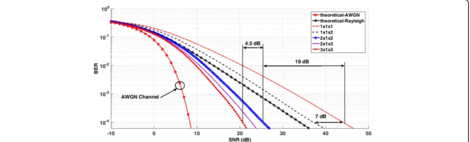
as the signal combining method. Figure 11 shows the
results of the simulations. The average BER curves for BPSK modulation are plotted for 2 × 1 × 2, 2 × 1 × 3 and 3 × 1 × 3 schemes. The BER curves for the multiplicative Rayleigh, Rayleigh, and AWGN are also illustrated. As shown, by using 2 × 1 × 2 configuration, the BER performance for a level of 10−4 is improved by 19 dB compared to the non-diversity (1 × 1 × 1) backscatter system. By using three transceivers (3 × 1 × 3), the improvement is 4.5 dB compared to the dual transceivers. In an ultimate state with massive
transceivers, the system performance approaches
AWGN channel.
7 Methods
A coherent query scheme is proposed for backscatter wireless communication with a single-tag device in a Rayleigh multipath channel. The proposed method uses the receiver feedback for providing appropriate phase information in the query end and thus spatial wave focusing in the tag antenna. Using the proposed method, the multiplicative Rayleigh fading channel statistics is altered in favor of BER. An analytical ap-proach is used to derive the fading channel statistics, and Monte-Carlo numerical simulations confirm the results. The BER performance is calculated numeric-ally for M- transmitter scheme with the channel feed-back. The provided method shifts the tag device complexity to the transmitter side in which a moder-ate complexity is acceptable. The approach is vali-dated experimentally by using SDR implementations. Two transmitters in the query end are synchronized by using a common clock distributor network, and feedback from one receiver is used to control the
phase difference between the transmitter carrier
signals. Details of system implementation using
MATLAB Simulink are provided, and the backscatter communication with a data-intensive tag device is demonstrated. Measurements show coherent summa-tion of the transmitted signal in the tag locasumma-tion,
using the coherent query scheme, that results
improved data connectivity in multipath channels.
8 Conclusions
Transmit diversity is proposed for backscatter wireless communication with a single-tag antenna. The primary objective is to combat deep fading in the backscatter channel for possible high data rate communication with a tag device. It is shown that using coherent query an-tennas on the reader side, with a feedback channel from one receiver, the overall backscatter link can be
im-proved by 10 dB for BER = 10−4 and BPSK modulation
using two transmitter antennas. The improvement is caused by the coherent summation of the multipath sig-nals in the forward path at the tag location, thanks to the receiver feedback. The channel statistics are
posi-tively modified by using multiple coherent and
phase-tuned transmitters, in which the equivalent chan-nel statistics can be converted from multiplicative Ray-leigh to a RayRay-leigh channel by increasing the number of the phase-tuned transmitters. The transmit array gain adds further to the system performance. The analytical expressions of the channel statistics are provided. It is also indicated that the transmit diversity performance is less sensitive to the phase deviation among the transmit-ters. Therefore, there is a broad range of relative phase values that a backscatter system with multiple transmit-ters can operate optimally. The system implementation is demonstrated by experimental measurements in an in-door channel.
Using receive diversity in addition to the transmit di-versity is recommended to improve the channel statistics and obtain better BER performance than in a Rayleigh channel. In the case of receiver diversity, only a feedback from one receiver in the chain can be used for tuning the phase differences among the transmitters. The diver-sity combining at the receiver can be applied following the forward channel focusing that improves the BER performance significantly.
Abbreviations
AGC:Automatic Gain Control; AWGN: Additive white Gaussian noise; BER: Bit error rate; BPSK: Binary phase shift keying; CW: Continues wave; EGC: Equal gain combining; EIRP: Effective isotropic radiated power; ISI: Inter-symbol interference; MIMO: Multiple input multiple output; NLOS: Non-line of sight; PDF: Probability density function; RCS: Radar cross section; RFID: Radio frequency identification; SDR: Software-defined radio; STC: Space-time coding; WSN: Wireless sensor network
Acknowledgements
The authors would like to thank Wireless Test Terminal Lab (WTTL), KNTU, for the help and support of the experiments. Also, the Department of Electronic Systems at NTNU and the Research Council of Norway under the project WINNOW grant no. 270957/O70 for supporting the visiting scholar.
Authors’contributions
The authors have contributed jointly to all parts on the preparation of this manuscript, and all authors read and approved the final manuscript.
Authors’information
Aminolah Hasanvand is a Ph.D. student at K. N. Toosi University of Technology, Tehran, Iran. Ali Khaleghi is an adjunct professor at K. N. Toosi University of Technology and is a scientist at the Norwegian University of Technology (NTNU), Trondheim, Norway. Ilangko Balasingham is a professor at the Norwegian University of Science and Technology (NTNU), Trondheim, Norway.
Ethics approval and consent to participate
Not applicable.
Consent for publication
Not applicable.
Competing interests
The authors declare that they have no competing interests.
Publisher’s Note
Springer Nature remains neutral with regard to jurisdictional claims in published maps and institutional affiliations.
Author details
1K. N. Toosi University of Technology (KNTU), Tehran, Iran.2Norwegian
University of Science and Technology (NTNU), Trondheim, Norway.3Signal
Processing Group, Department of Electronic Systems, Norwegian University of Science and Technology, Electro Building, NTNU, N-7491 Trondheim, Norway.
Received: 3 November 2017 Accepted: 19 June 2018
References
1. D M Dobkin,The Rf in RFID: Uhf RFID in Practice: Newnes; 2012. 2. S Roy, V Jandhyala, JR Smith, D Wetherall, BP Otis, R Chakraborty, M
Buettner, DJ Yeager, Y-C Ko, AP Sample, RFID: from supply chains to sensor nets. Proc. IEEE98(9), 1583–1592 (2010)
3. K Han, K Huang, Wirelessly powered backscatter communication networks: modeling, coverage, and capacity. IEEE Trans. Wirel. Commun.16(4), 2548– 2561 (2017)
4. C Psomas, I Krikidis, Backscatter communications for wireless powered sensor networks with collision resolution. IEEE Wireless Communications Letters6(5), 650–653 (2017)
5. G Wang, F Gao, R Fan, C Tellambura, Ambient backscatter communication systems: detection and performance analysis. IEEE Trans. Commun.64(11), 4836–4846 (2016)
6. X Zhou, G Wang, Y Wang, J Cheng, An approximate BER analysis for ambient backscatter communication systems with tag selection. IEEE Access
5, 22552–22558 (2017)
7. Y Liu, G Wang, Z Dou, Z Zhong, Coding and detection schemes for ambient backscatter communication systems. IEEE Access5, 4947–4953 (2017)
8. P Nikitin, K Rao, R Martinez, Differential RCS of RFID tag. Electron. Lett.43(8), 431–432 (2007)
9. D Kim, MA Ingram, WW Smith, Measurements of small-scale fading and path loss for long range RF tags. IEEE Trans. Antennas Propag.51(8), 1740– 1749 (2003)
10. SJ Thomas, MS Reynolds,A 96 Mbit/sec, 15.5 pJ/bit 16-QAM modulator for UHF backscatter communication. IEEE International Conference. 185–190 (2012)
12. J-S Kim, K-H Shin, S-M Park, W-K Choi, N-S Seong, Polarization and space diversity antenna using inverted-F antennas for RFID reader applications. Antennas and Wireless Propagation Letters, IEEE5(1), 265–268 (2006) 13. MS Abouzeid, L Lopacinski, E Grass, T Kaiser, R Kraemer,Efïicient and
low-complexity space time code for massive MIMO RFID systems. 12th Iberian Conference on IEEE. 1–6 (2017)
14. MA Ingram, MF Demirkol, D Kim, inProc. ISSSE. Transmit diversity and spatial multiplexing for RF links using modulated backscatter. Proceedings of the 2001 International Symposium on Signals, Systems, and Electronics (ISSSE
’01). (Tokyo, 2001)
15. A Rahmati, L Zhong, M Hiltunen, R Jana,Reliability techniques for RFID-based object tracking applications,(2007) pp. 113–118
16. JD Griffin, GD Durgin,Multipath fading measurements for multi-antenna backscatter RFID at 5.8 GHz. IEEE International Conference on. 322–329 (2009)
17. C Boyer, S Roy, Space time coding for backscatter RFID. IEEE Trans. Wirel. Commun.12(5), 2272–2280 (2013)
18. C He, X Chen, ZJ Wang, W Su, On the performance of MIMO RFID backscattering channels. EURASIP J. Wirel. Commun. Netw.2012(1), 1–15 (2012)
19. C He, ZJ Wang, VCM Leung, Unitary query for the MxLxN MIMO backscatter RFID channel. IEEE Trans. Wirel. Commun.14(5), 2613–2625 (2015) 20. C He, ZJ Wang, C Miao, Query diversity schemes for backscatter RFID
communications with single-antenna tags. IEEE Trans. Veh. Technol.66(8), 6932-6941 (2017)
21. AJS Boaventura, NB Carvalho, The design of a high-performance multisine RFID reader. IEEE Transactions on Microwave Theory and Techniques.65(9), 3389-3400 (2017)
22. H-C Liu, Y-F Chen, Y-T Chen, A frequency diverse Gen2 RFID system with isolated continuous wave emitters. J. Networks2(5), 54–60 (2007) 23. D Chizhik, G Foschini, R Valenzuela, Capacities of multi-element transmit
and receive antennas: correlations and keyholes. Electron. Lett.36(13), 1 (2000)
24. C Boyer, S Roy, Invited paper-backscatter communication and RFID: coding, energy, and MIMO analysis. IEEE Trans. Commun.62(3), 770–785 (2014) 25. D Hotte, R Siragusa, Y Duroc, S Tedjini, Radar cross-section measurement in
millimetre-wave for passive millimetre-wave identification tags. IET Microwaves, Antennas & Propagation9(15), 1733–1739 (2015)
26. M. K. Simon, Probability distributions involving Gaussian random variables: a handbook for engineers and scientists: (Springer Science & Business Media, New York, 2007).