85 | P a g e
ISTF-PID Based Single Joint Robotic Arm Control
Amitosh Mittal
1, Arjun Swami
2, Bhavya Bansal
3Anish Krishna
4, Prof.Prerna Gaur
51,2,3,4,5
Instrumentation and Control Engineering, Netaji Subhas Institute of Technology, (India)
ABSTRACT
The objective of this research work is to compare the different classical tuning methods for the PID gains against an intelligent tuning technique that uses fuzzy logic controller for tuning the PID gains. The classical tuning techniques that have been used in this work are Cohen Coon as well as Ziegler Nichols. The Intelligent Tuning methodology used is Improved Self Tuning Fuzzy-PID. The tuning is performed using a PID controller on a single joint robotic arm. The robotic arm is moved using a servo motor. The comparison between the different tuning techniques is made based on the settling time of the object that is being balanced on the robotic arm.
Keywords- Cohen Coon, Improved Self Tuning Fuzzy-PID, PID, Single Joint Robotic Arm, Ziegler
Nichols
1. INTRODUCTION
In today‟s massively industrialized world, where time is of the essence and value for money is the foremost
parameter in determining the performance of enterprises, automation is the need of the hour. It has
revolutionised the face of industry in recent times, with human beings being replaced by intelligent machines
and devices to perform mundane and repetitive tasks.
A Robotic Arm is a programmable, mechanical arm that performs functions similar to a human arm. It may be a
complete automation system by itself, or a part of a larger machine. It can be controlled to perform desired tasks
such as welding, gripping, spinning, balancing, painting, performing surgeries like LASIK etc. Robotic Arm is
also used in other application including space retrieval systems, as well as intricate CNC systems like 3D
printing machines. Applications employing Robotic Arm like in industries, surgeries, and defence need to be
very precise and quick in their action. As an example, LASIK surgery which works on human body as a subject,
needs precise control, otherwise, there can be dire consequences.
To overcome the shortcoming as mentioned above, various classical and intelligent PID tuning techniques have
been applied [1]. The combination of proportional, integral and derivative control is called the PID controller.
PID controllers are mostly used to regulate the time-domain behaviour of various types of dynamic plants [2].
The popularity of the PID controllers resides in the fact that, the PID controllers can usually provide good
closed-loop response characteristics [3]. The PID gains have been controlled using the classic control tuning
techniques of Ziegler-Nichols and Cohen Coon which are then compared to an Intelligent tuning technique that
uses fuzzy logic to control the robotic arm [4]. Ziegler-Nichols tuning method heuristically tunes the PID gains.
However, it can only work satisfactorily on processes where dead time is less than half the length of the time
86 | P a g e
in the Improved Self Tuning Fuzzy (ISTF)-PID control method the values of the parameters of the PID
controller such as Kp, Ki, Kd are obtained using the fuzzy controller [7]. The control action in a fuzzy logic
controller can be expressed with simple „IF THEN‟ rules. A fuzzy logic controller can cover a wider range of
operating conditions and can operate under noise and other disturbances [8].
D.C. servo motors provides excellent control of speed for acceleration and deceleration of Robotic Arm. D.C.
servo motors are usually less expensive, more robust and have speed torque characteristics superior to A.C.
motors [9]. D.C. servo motors have a long-history of being used as adjustable speed control machines and
various methods have been evolved for this purpose. NI myRIO is an embedded hardware device based on
technology used in industry for controls and robotics. It is a real-time embedded evaluation board used to
develop applications that utilize its on board FPGA and microprocessor. It has all the I/O and processing power
needed to control the robots. It requires LabVIEW (Laboratory Virtual Instrument Engineering Workbench).
In this work, the various key components of the project are highlighted along with the mechanical, electrical and
software elements. Various control techniques have been compared to determine the optimal technique that can
be used.
II. DESCRIPTION OF SINGLE JOINT ROBOTIC ARM
The robotic technology has quickly progressed and this has led to the application of robots in diverse fields such
as industries, guarding and domestic. There are six degrees of freedom associated with a robotic arm. Each
degree of freedom is a join on a robot arm [9]. This joint enables the arm to translate or rotate. A single joint
Robot arm is a system with one degree of freedom [10]. Having both electrical and mechanical parameters, a
single joint robot arm is an application example of a Mechatronics electromechanical system used in industrial
automation.
Intentional speed variation carried out manually or automatically is referred to as speed control. D.C. servo
motors are most used for wide range of speed control. A servomotor uses position feedback to control its motion
and final position. The measured position and command position are compared and an error signal is generated.
This causes the motor to rotate in either direction, as needed to bring the output shaft to the appropriate position.
When the error signal reduces to zero, the motor stops.
To simplify the modeling process, linear approximations are used in such a way that the approximation does not
lead to major deviations from reality [11-12]. Single joint robot arm system consists of three main parts; arm,
connected to actuator through gear train with gear ratio, n.
The robotic arm has the following nominal values: arm length, L=0.4 m; arm mass, M=1kg; and viscous
damping constant, b = 0.09 N.sec/m. The nominal values for the various parameters of electric motor used:
Vin=12 Volts; Jm=0.02 kgmÇ, bm =0.03; Kt =0.023 N-m/A; Kb =0.023 Vs/rad; R=1 Ohm; L=0.23 Henry;
87 | P a g e
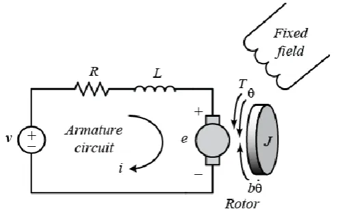
Figure 1:
circuit diagram of a dc servomotor The transfer function of a single joint robotic arm without anyload can be approximated to the following equations:
(1)
(2)
To compensate for the effect of loading, we must calculate and replace Jeq and beq. This is done by using the
following equations and substituting the appropriate values:
(3)
(4)
(5)
Figure 2:simplified schematic model of a single joint robotic arm [13] Substituting, we obtain, Jeq,
88 | P a g e
Obtaining the total damping, beq, gives:
Substituting the above values in equation 3.1 and using the nominal values of robotic arm and the motor, we
obtain:
(6)
The Equation 6 has been used as the transfer function of the robotic arm, and thus the plant, in all further
mathematical models.
III. PID GAIN TUNING TECHNIQUES
The combination of proportional, integral and derivative control is called the PID controller. PID controllers are
mostly used to regulate the time-domain behaviour of various types of dynamic plants. The popularity of the
PID controllers resides in the fact that, the PID controllers can usually provide good closed-loop response
characteristics.
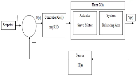
Figure 3:
robotic arm balance control systemIn this research work, classical tuning techniques like Ziegler Nichols and Cohen Coon are compared with the
new and adaptive control technique, that is, Improved Self Tuning Fuzzy PID or ISTF-PID.
3.1 Ziegler Nichols
The Ziegler-Nichols tuning method is used for the tuning of PID controller using Heuristics. In this method, the
89 | P a g e
Table 1: Determination of Ziegler Nichols parameters
Control Type
k
pt
it
dP
0.5k
u-
-
PI
0.45k
ut
u/12
-
PD
0.8k
u-
t
u/8
PID
0.6k
ut
u/2
t
u/8
3.2 Cohen-Coon
The response of most of the process under a step change in input yields a sigmoidal shape which can be
adequately approximated by the response of a first order process with dead time. This approximated response
has gain K, time constant and delay time td.The control parameters can then be determined by substituting the
values in the given table.
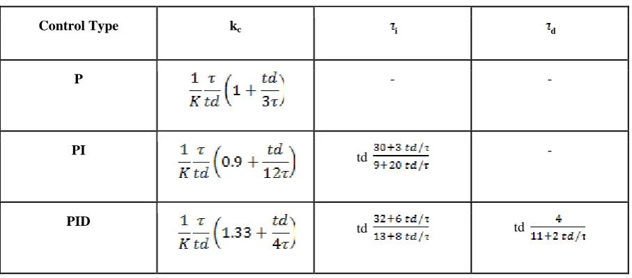
Table 2: Determination of Cohen-Coon parameters
Control Type kc i d
P - -
PI
td -
PID td td
3.3 Improved Self Tuning Fuzzy PID
In the ISTF-PID tuning technique, A rule-base has been created for the system in accordance with the arm
length and the arm range. This technique is an improvement to the previous tuning techniques since it uses the
fuzzy logic controller to tune the parameters of PID at the run time [14]. The tuning of the parameters during
90 | P a g e
Figure 4:
block diagram of an ISTF-PIDLike the previous techniques, the error signal is taken as the difference of set-point and feedback from the
sensor. The error signal is fed into the fuzzy logic controller. But in this technique, along with the error signal,
derivative of error signal is also fed into the fuzzy logic controller.
The output from the fuzzy logic controller is the PID parameters. The parameters along with the error signal are
put as the input to the PID controller. The output from the PID controller is then fed to the plant consisting of
PWM servo motor and the robotic arm. The feedback is taken using the infrared sensor. Centroid
Defuzzification is used to get the crisp output.
Table 3:
fuzzy rule-base matrix for ISTF-PID parametersde(t)/dt
e(t
)
LN
SN
Z
SP
LP
LN
LP, LP, LN
LP, LP, LN
SP, LP, SN
Z, LP, Z
SN, LP, SP
SN
SN, LP, Z
SN, LP, SP
SN, LP, SP
LN, SP, SP
LN, SP, LP
Z
Z, SP, SN
Z, SP, SN
Z, SP, SN
SN, Z, Z
SN, Z, Z
SP
SP, LN, Z
SP, LN, LN
SP, SN, SN
Z, SN, SN
Z, SN, SN
LP
LP, LN, LN
LP, LN, LN
LP, LN, LN
LP, LN, LN
SP, LN, LN
IV. WORKING AND RESULTS
This section briefly explains the working of the single joint robotic arm along with the results obtained with the
use of different tuning techniques. The microcontroller used for the experiment is myRIO. The software
environment used for the experiment is LabVIEW.
The error signal, e(s) is the difference between the set-point and the feedback from the infrared sensor. This
signal is fed into the controller that is driven by myRIO. The plant consists of servo motor, that acts as an
91 | P a g e
Figure 5:
complete setup of the single-joint robotic armIn this experiment, three points were marked on the robotic arm, namely, „A‟, „B‟, and „C‟. Point A is farthest
from the set-point and point „C‟ being the closest to the given set-point. The set-point in this experiment is taken
to be of „50% of arm length‟. While performing the experiment the ball was placed on these points and the time
taken by the ball to attain the given set-point against different controllers was noted.
92 | P a g e
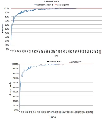
Figure 6:
plot between zn response and ideal response for point (a) A (b) B and (c) C93 | P a g e
Figure 7:
plot between c-c response and ideal response for point (a) A (b) B and (c) C94 | P a g e
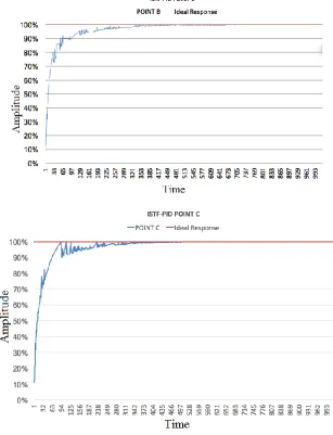
Figure 8:
plot between ISTF-PID response and ideal response for point (a) A (b) B (c) CThe results are summarized in the table below.
Table 4:
Results obtainedTUNING
POINT
ZIEGLER
NICHOLS
COHEN-COON
ISTF-PID
A
9.69
9.31
8.63
B
7.73
7.54
6.93
C
6.68
6.12
5.76
V. CONCLUSION
In this paper, we have compared different methodologies used for the tuning of PID controllers that is used for
95 | P a g e
utilised to control the balance arm based system. The tuning techniques used were Ziegler Nichols, Cohen Coon
and Improved Self Tuning Fuzzy PID(ISTF-PID) tuning technique. The results obtained from the experiments
were analysed and compared as mentioned in the table-4. On comparing the Ziegler Nichols and Cohen Coon
based tuning techniques, it is observed that the settling time of Cohen Coon method is relatively lower than
Zeigler Nichols method under all test cases, hence it can be concluded that Cohen Coon is a better tuning
technique with respect to this model of single joint robotic arm. Similarly, when the Cohen Coon method is
compared to the Improved Self Tuning Fuzzy PID(ISTF-PID) technique, it is observed that the settling time of
Improved Self Tuning Fuzzy PID technique is relatively lower than Cohen Coon method, under all the test
cases. Therefore, the Fuzzy based PID tuning technique is found to be superior to the Cohen Coon based
method.
The PID based control tuning techniques and study analysis of their responses were the main area of
concentration in this paper and the results obtained clearly determine that the Improved Self Tuning Fuzzy PID
(ISTF-PID) tuning is by far the most superior as it guarantees, in general, very good performances in the set
point and load disturbance step responses. Also, this tuning technique requires a modest implementation effort.
Hence, its practical implementation in industrial environments appears to be very promising.
In the future research work, we would be tuning the PID controller for single joint robotic arm using Artificial
Neural Networks and Genetic algorithm and comparing the results with the Improved Self Tuning Fuzzy PID
(ISTF-PID) tuning technique.
REFERENCES
[1] Michael J. Neath, Akshya K. Swain, Udaya K. Madawala and DuleepaJ.Thrimawithana, “An Optimal
PID Controller for a Bidirectional Inductive Power Transfer System Using Multiobjective Genetic
Algorithm,” IEEE Transactions on Power Electronics, vol. 29, no. 3, pp. 1523-1531, 2014.
[2] Chih-Min Lin, Ming-Hung Linand Chun-Wen Chen, “SoPC-Based Adaptive PID Control System Design
for Magnetic Levitation System,”IEEE Systems Journal, vol. 5, no. 2, pp. 278-287, 2011.
[3] Anil Kumar Yadav and Prerna Gaur, “Robust Adaptive Speed Control of Uncertain Hybrid Electric Vehicle using Electronic Throttle Control with Varying Road Grade,” Non-linear Dynamics, vol. 76, no. 1,
pp. 305-321, 2014.
[4] Anil Kumar Yadav, Prerna Gaur, A.P. Mittal and Masood Anzar, “Comparative Analysis of Various
Control Techniques for Inverted Pendulum,” In proc. Of IICPE-2010, New Delhi, 2011.
[5] Åström, Karl Johan, and Tore Hägglund. "Revisiting the Ziegler–Nichols step response method for PID
control." Journal of process control 14, no. 6 (2004): 635-650.
[6] Anil Kumar Yadav and Prerna Gaur, “AI-based adaptive control and design of autopilot system for
non-linear UAV,” Sadhana, vol. 39, no. 4, pp. 765–783, 2014.
[7] K.K. Ahn and D.Q. Truong, “Online tuning fuzzy PID controller using robust extended Kalman filter,”
Journal of Process Control, vol. 19, no. 6, pp. 1011–1023, 2009.
[8] Anil Kumar Yadav and Prerna Gaur, “Improved Self Tuning Fuzzy PID Speed Control of Non-linear
Hybrid Electric Vehicles”,ASME journal,doi:10.1115/1.4033685, Revised May 16, 2016.
96 | P a g e
[10] Rajeev, Agrawal, KabirajKoushik, and Singh Ravi. "Modeling a controller for an articulated robotic arm."
Intelligent Control and Automation 2012 (2012).
[11] IJCS_37_2_04 (Advance online publication: 13 May 2010). MohdRiduwan, Ghazali, SuidMohdHelmi,
Ibrahim Zuwairie, Saealal Muhammad Salihin, Mohd Zaidi, and MohdTumari. "Single input fuzzy logic
controller for flexible joint manipulator." International Journal of Innovative Computing, Information and
Control 12, no. 1 (2016): 181-191.
[12] Koivo, A., and Ten-HueiGuo. "Adaptive linear controller for robotic manipulators." IEEE Transactions on
Automatic Control 28, no. 2 (1983): 162-171.
[13] ZeyadAssiObaid, Member, IAENG, NasriSulaiman, M. H. Marhaban And M.N. Hamidon, Member,
IAENG “Analysis and Performance Evaluation of PD- like Fuzzy Logic Controller Design Based on Matlab and FPGA” IAENG International Journal of Computer Science, 37:2.
[14] Zhi-Wei Woo, Hung-Yuan Chung and Jin-Jye Lin, “A PID type fuzzy controller with self-tuning scaling factors,” Fuzzy Sets and Systems, vol. 115, no.2, pp. 321-326, 2000.
[15] Lin, F-J., and S-L. Chiu. "Adaptive fuzzy sliding-mode control for PM synchronous servo motor drives."