Y.Mastanamma
1, S.Deepthi
2Associate Professor/HOD, EEE Department , Bhoj Reddy Engineering college for women, Saidabad, Hyderabad, Telangana, India
Asst. Professor, Department EEE, Bhoj Reddy Engineering college for women, Saidabad, Hyderabad, Telangana
ABSTRACT: In order to meet power needs, taking into account economical and environmental factors, wind energy conversion is gradually gaining interests as a suitable source of renewable energy. A Wind Energy Conversion System (WECS) differs from a conventional power system. The power output of a conventional power plant can be controlled whereas the power output of a WECS depends on the wind. In this paper the steady state characteristics of a WECS using doubly fed induction generator (DFIG) is proposed and simulated Wind Turbine and doubly-fed induction machine used in generating mode to produce electrical energy on a power network. Simulation analysis is performed to investigate harmonic analysis for DFIG based WECS.
KEYWORDS: Wind energy conversion system, doubly fed induction generator, simulation, MATLAB.
I.INTRODUCTION
Renewable energy sources currently supply about 10 % of the world energy demand. These energy sources will become increasingly important in the future. Wind energy is a form of solar energy produced by heating of the earth’s surface. As a power source, wind power is less predictable than solar power, but it is also typically available for more hours in a given day. Wind resources are influence by the type of the land surface and the elevation of the land surface. Generally, if the land is in high elevation then it is good for wind energy conversion. Since the wind speed is extremely important for the amount of energy a wind turbine can convert it to electricity. The power in the wind can be defined as follows,
PW
Where, ρ: Air density, kg/m3.
A: Cross sectional area of wind parcel,
V: The wind speed, m/sec.
It is clear that it is clear that the wind power is affected by the wind speed. The wind speed increases with the
Fig.1. Actual WTG output power with the wind speed
II. GENERATOR SELECTION FOR WIND ENERGY
An important step for installation of wind energy system is to select the turbine rating, the generator and the distribution system. In general, the output characteristics of the wind turbine power do not follow exactly those of the generator power; so they have to be matched in the most reasonable way possible. Based on the maximum speed expected for the turbine and taking into account the cubic relationship between the wind speed and the generated power, the designer must select the generator and the gearbox so as to match these limits. The most sensitive point here is the correct selection of the rated speed for the generator. If it is too low, the high speed of the primary source wind will be wasted; if it is too high, the power factor will be harmed. The characteristics of the commercially available turbines and generators must be matched to the requirements of the project with regard to cost, efficiency, and maximum generated power is an iterative design process. Several types of generators can be coupled to the rotating wind power turbines: dc and ac types, parallel and compound dc generators, with permanent magnets or electrical field excitation, synchronous or non synchronous, and, especially, induction generators. The dc machines are not usually employed because of their high cost, bulky size, and maintenance needs. The right choice of generator depends on a wide range of factors related to the primary source, the type of load, and the speed of the turbine. Besides, systems differ with respect to their applications, whether they are stand-alone or connected to the grid, their degree of interruptibility, and the quality and cost of their output. Because of the way it works as a motor or generator, the possibility of variable speed operation, and its low cost compared to other generators, the induction machine offers advantages for rotating power plants, like the wind power, in both standalone and interconnected applications.
III. DOUBLY FED INDUCTION GENERATOR
A very important machine, typically used for high power applications, is the doubly fed induction generator (DFIG). The DFIG is a wound rotor machine where the rotor circuit is connected to an external variable voltage and frequency source via slip rings and the stator is connected to the grid network. There is also a possibility of altering the rotor reactance b y effectively modulating some inductors in series with the original rotor reactance. Adjusting the frequency of the external rotor source of current controls the speed of the doubly fed induction generator, which is usually limited to a 2:1 range. Doubly fed machines were not very popular in the past due to the maintenance required for the slip rings. More recently, with the development of new materials, powerful digital controllers and power electronics, the doubly fed induction generator became a solution in power generation for up to several hundreds of kW ratings. Power converters usually make up the need for a variable frequency source for the rotor. As it is said above, the control of doubly fed induction generators can be exerted either through the stator or rotor variables. The controllable stator variables are number of poles, voltage and frequency. The rotor variables for squirrel cage rotors can be design resistance, design reactance and speed. The doubly fed induction generator is affected by the second power of the grid voltage and the controllable variables are current, voltage, frequency, and voltage phase shift with respect to the stator voltage angle. Obviously, in most applications, this setup can be simplified.
converter in both super and sub-synchronous speed ranges. As a result, the machine can be controlled as a generator or a motor in both super and sub-synchronous operating modes realizing four operating modes. Below the synchronous speed in the motoring mode and above the synchronous speed in the generating mode, rotor-side converter operates as a rectifier and stator-side converter as an inverter, where slip power is returned to the stator. Below the synchronous speed in the generating mode and above the synchronous speed in the motoring mode, rotor-side converter operates as an inverter and stator- side converter as a rectifier, where slip power is supplied to the rotor[3]. At the synchronous speed, slip power is taken from supply to excite the rotor windings and in this case machine behaves as a synchronous machine.
mechanical power and the stator electric power output are computed as follows Pr = Tm * ωr
Ps = Tem * ωs
For loss less generator the mechanical equation is:
In steady state at fixed speed for a loss less generator Tm = Tem and
Pm = Ps + Pr
Pr = Pm – Ps = Tem ωs = -sPs
Where, S defined as the slip of the generator. Generally the slip is much lower than 1 and consequently, Pr is
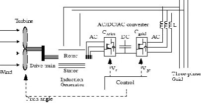
only a fraction of Ps. Since Tm is positive for power generation and since ωs is positive and constant for a constant frequency grid voltage, the sign of Pr is a function of the slip sign. Pr is positive for negative slip (speed greater than synchronous speed) and it is negative for positive slip (speed lower than synchronous speed). For super synchronous speed operation, Pr is transmitted to DC bus capacitor and tends to rise the DC voltage. For sub-synchronous speed operation, Pr is taken out of DC bus capacitor and tends to decrease the DC voltage. Cload is used to generate or absorb the power Pgc in order to keep the DC voltage constant. In steady-state for a lossless AC/DC/AC converter Pgc is equal to Pr and the speed of the wind turbine is determined by the power Pr absorbed or generated by C rotor. The phase-sequence of the AC voltage generated by Crotor is positive for sub-synchronous speed and negative for super synchronous speed. The frequency of this voltage is equal to the product of the grid frequency and the absolute value of the slip. Crotor and Cload have the capability for generating or absorbing reactive power and could be used to control the reactive power or the voltage at the grid terminals.
Fig. 4. Turbine power characteristics
The rotor-side converter is used to control the wind turbine output power and the voltage measured at the grid terminals.
IV. DOUBLY FED INDUCTIONGENERATOR FOR WIND TURBINES
Mainly due to the fact that the power electronic converter only has to handle a fraction (20–30%) of the total power[1].Therefore, the losses in the power electronic converter can be reduced, compared to a system where the converter has to handle the total power. In addition, the cost of the converter becomes lower. There exists a method that uses controllable external rotor resistances
.
Fig.7. Variable-speed wind turbine with DFIG
Some of the drawbacks of this method are that energy is unnecessary dissipated in the external rotor resistances and that it is not possible to control the reactive power.
For variable-speed systems with limited variable-speed range, e.g.30% of synchronous speed, the DFIG can be an interesting solution. As mentioned earlier the reason for this is that power electronic converter only has to handle a fraction (20–30%) of the total power. This means that the losses in the power electronic converter can be reduced compared to a system where the converter has to handle the total power. In addition, the cost of the converter becomes lower. The stator circuit of the DFIG is connected to the load while the rotor circuit is connected to a converter via slip rings with a back to back converter [2].
A B C a b c sc1 Continuous 1 Vref (pu) Vabc (pu)
Vd_ref (pu) Vabc_inv m Voltage Regulator z 1 Vf _ m A B C Pm Synchronous Condenser 480V 300kVA
Double click to display Turbine characteristics Scope1 A B C a b c SC C -PWM IGBT Inverter PF Correction Capacitor
75 kvar C
b
c Measure
ABC
Main Load 1kW C C LC Filter [w_ASM] [Vabc_SC] m Vf Excitation Uref Pulses Discrete PWM Generator C c Asynchronous Generator 480V 275kVA A B C a b c 3-Phase Breaker1
ABC abc
3-Phase Breaker 0
0 kW
ASM speed (pu)
modulation index Vabc (pu)
Fig.8. Simulink model of DFIG driven wind energy conversion systems
Fig.9. Wind turbine simulink block diagram
The above system is the subsystem of the wind turbine model where the wind velocity and reference speed of the turbine is given as the input.
VI. RESULTS
The wind turbine is assumed to be operated with variable speed so that it will operate in the peak power tracking mode. A varying wind speed profile is applied to the generator to investigate its performance. Due to variation of wind velocity power generated by the machine can also be changed.
Fig.11.waveforms of Dc voltage, inverter output voltage, load voltage and Modulation index respectively with DFIGWEC supply and conventional power supply
The harmonic level in the three phase grid
Voltage wave forms are estimated by the concept of THD and it satisfies the IEEE 519-1992 standard. This is shown in the Fig. 12.
Fig.12. FFT analysis of the load voltage waveform
VII. CONCLUSIONS
The basic operation of DFIG and it’s controls using AC/DC/AC converter is simulated using Matlab/Simulink. I n t o t a l s i mul a t i o n t i m e , ha l f o f t he t i me o p e r a t e d wi t h wi nd p o we r a nd r e ma i ni n g wi t h conventional supply and observed wa ve fo r ms o f load side and wind turbine side parameters. Here the is also connected to the load as backup. Considering the results it can be said that DFIG driven wind turbine proved to be more reliable and stable system with less total harmonic distortion(THD) and so gives stable and smooth performance.
REFERENCES
[1] Feng Wu, Xiao-Ping Zhang, Keith Godfrey, and Ping Ju, “Modeling and Control of Wind Turbine with Doubly Fed Induction Generator”, IEEE PES Conference on Power Systems Conference and Exposition, pp. 1404-1409, 2006.
[2] Satish Choudhury, Kanungo Barada Mohanty, B. Chitti Babu, “Performance Analysis of Doubly fed Induction Generator For Wind Energy Conversion System” The 5th PSU-UNS International Conference on Engineering and Technology (ICET-2011), Phuket, pp. 532-536, 2-3 May 2011 [3] Huaqiang ZHANG, Zhixin WANG, “Study on Modeling and Simulation of Double-Fed Induction Wind Power Generator Control System”,
International Conference on Sustainable Power Generation and Supply, pp. 1-5, 6-7 April 2009.
[4] H. Sediki, Dj. Ould Abdeslam, T. Otmane-cherif, A. Bechouche, K. Mesbah, “Steady-State Analysis and Control of Double Feed Induction Motor”, World Academy of Science, Engineering and Technology 61 2012.