111 | P a g e
AN ACTIVE POWER FILTER PERFORMANCE
IMPROVED BY USING PREDICTIVE CONTROL
SCHEME FOR RENEWABLE POWER GENERATION
SYSTEMS
Priyanka Baban Bhoyar
1, K. Bahadure
2ABSTRACT
An active power filter enforced with a four-leg voltage-source inverter employing a predictive control scheme is
presented. The use of a four-leg voltage-source inverter permits the compensation of current harmonic
elements, as well as unbalanced current generated by single-phase nonlinear loads. A detailed yet easy
mathematical model of the active power filter, together with the result of the equivalent grid impedance, is
derived and used to design the predictive control algorithm. The compensation performance of the proposed
active power filter and therefore the associated control scheme below steady state and transient operating
conditions is demonstrated through simulations and simulation results.
Keywords: Active Power Filter, Current Control, Four-Leg Converters, Predictive Control,
Enhanced Phased Locked Loop (EPLL).
I. INTRODUCTION
Renewable generation affects power quality as a result of its nonlinearity, since solar generation plants and wind
power generators should be connected to the grid through high-power static PWM converters [1]. The non
uniform nature of power generation directly affects voltage regulation and creates voltage distortion in power
systems. This new scenario in power distribution systems would require additional sophisticated compensation
techniques.
Although active power filters enforced with three-phase four-leg voltage-source inverters (4L-VSI) have already
been presented within the technical literature [2]–[6], the first contribution of this paper is also a predictive
control algorithm designed and enforced specifically for this application. Historically, active power filters are
controlled using pre tuned controllers, like PI-type or adaptative, for the present as well as for the dc-voltage
loops [7], [8]. PI controllers should be designed based on the equivalent linear model, whereas predictive
controllers use the nonlinear model, which is closer to real operating conditions. an accurate model obtained
using predictive controllers improves the performance of the active power filter, particularly throughout
transient operating conditions, as a results of it'll quickly follow the current-reference signal whereas
maintaining a constant dc-voltage.
This paper presents the mathematical model of the 4L-VSI and also the principles of operation of the proposed
predictive control scheme, together with the design procedure. The complete description of the selected current
112 | P a g e
filter and also the effectiveness of the associated control theme compensation are demonstrated through
simulation and valid with simulation results obtained throughout a 2 kVA laboratory image.
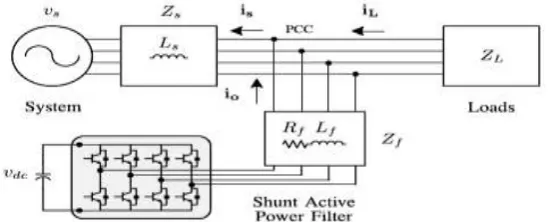
Fig. 1. Stand-alone hybrid power generation system with a shunt active power filter.
Fig. 2. Three-phase equivalent circuit of the proposed shunt active power filter.
II. FOUR-LEG CONVERTER MODEL
Fig. 1 shows the configuration of a typical power distribution system with renewable power generation. It
consists different kinds of power generation units and different kinds of loads. Renewable sources, like wind
and sunlight, are generally used to generate electricity for residential users and small industries. Both kinds of
power generation use ac/ac and dc/ac static PWM converters for voltage conversion and battery banks for long
term energy storage. These converters perform maximum power point tracking to extract the maximum energy
attainable from wind and sun. The power consumption behavior is random and unpredictable, and also, it should
be single- or three-phase, balanced or unbalanced, and linear or nonlinear. An active power filter is connected in
parallel at the point of common coupling to compensate current harmonics, current unbalance, and reactive
power. It’s composed by an capacitor, a four-leg PWM converter, and a first-order output ripple filter, as shown
in Fig. 2. This circuit considers the power system equivalent impedance Zs, the converter output ripple filter
impedance Zf, and also the load impedance ZL.
The four-leg PWM converter topology is shown in Fig. 3. This converter topology is similar to the conventional
113 | P a g e
switching states from 8 to 16, rising control flexibility and output voltage quality, and is suitable for current
unbalanced compensation.
Fig. 3. Two-level four-leg PWM-VSI topology.
The voltage in any leg x of the converter, measured from the neutral point (n), can be expressed in terms of
switching states, as follows:
Vxn = Sx – Sn, x=u, v, w,n. (1)
The mathematical model of the filter derived from the equivalent circuit shown in Fig. 2 is
Vo = vxn – Req io – Leq (2)
Where Req and Leq are the 4L-VSI output parameters expressed as Thevenin impedances at the converter output
terminals Zeq. Therefore, the Thevenin equivalent impedance is determined by a series connection of the ripple
filter impedance Zf and a parallel arrangement between the system equivalent impedance Zs and the load
impedance ZL
For this model, it is assumed that ZL »Zs, that the resistive part of the system’s equivalent impedance is
neglected, and that the series reactance is in the range of 3–7% p.u., which is an acceptable approximation of the
real system. Finally, in (2) Req = Rf and Leq = Ls + Lf.
III.
DIGITAL PREDICTIVE CURRENT CONTROL
The diagram of the proposed digital predictive current control scheme is shown in Fig. 4. This control scheme is
essentially an optimization algorithm and, therefore, it's to be enforced during a microprocessor. Consequently,
the analysis should be developed using discrete mathematics in order to consider about additional restrictions
like time delays and approximations.
114 | P a g e
The main characteristic of predictive control is the use of the system model to predict the longer term behavior
of the variables to be controlled. The controller uses this information to select the optimum switching state that
may be applied to the power converter, according to predefined improvement criteria. The predictive control
algorithm is simple to implement and to know, and it may be enforced with 3 main blocks, as shown in Fig. 4.
1) Current Reference Generator: This unit is designed to generate the desired current reference that's used to
compensate the undesirable load current elements. During this case, the system voltages, the load currents, and
also the dc-voltage converter are measured, whereas the neutral output current and neutral load current are
generated directly from these signals (IV).
2) Prediction Model: The converter model is employed to predict the output converter current. Since the
controller operates in discrete time, both the controller and also the system model should be represented during a
discrete time domain. The discrete time model consists of a recursive matrix equation that represents this
prediction system. this implies that for a given sampling time Ts, knowing the converter switching states and
control variables at instant kTs, it's attainable to predict the next states at any instant [k + 1]Ts .Due to the
first-order nature of the state equations that describe the model in (1)–(2), a sufficiently accurate first-first-order
approximation of the derivative is considered during this paper
The 16 possible output current predicted values can be obtained from (2) and (4) as
As shown in (5), in order to predict the output current ioat the instant (k + 1), the input voltage value voand the
converter output voltage vxN, are required. The algorithm calculates all 16 values associated with the possible
combinations that the state variables can achieve.
3) Cost Function Optimization: In order to select the optimal switching state that must be applied to the power
converter, the 16 predicted values obtained for io[k + 1] are compared with the reference using a cost function g,
as follows:
The output current (io) is equal to the reference (i*o) when g = 0. Therefore, the improvement goal of the value /
the price function is to attain a g value near to zero. The voltage vector vX that minimizes the cost function is
chosen and applied at ensuing sampling state. Throughout every sampling state, the switching state that
generates the minimum price of g is chosen from the 16 possible function values. The algorithm selects the
115 | P a g e
IV.
CURRENT REFERENCE GENERATION
A dq-based current reference generator scheme is employed to get the active power filter current reference
signals. This scheme presents a quick and accurate signal tracking capability. This characteristic avoids voltage
fluctuations that deteriorate the current reference signal affecting compensation performance. The current
reference signals are obtained from the corresponding load currents as shown in Fig. 5. This module calculates
the reference signal currents needed by the converter to compensate reactive power, current harmonic and
current imbalance. The displacement power factor (sinφ(L) ) and also the maximum total harmonic distortion of
the load (THD(L)) defines the relationships between the apparent power needed by the active power filter, with
respect to the load, as shown
Where the value of THD(L) includes the maximum compensable harmonic current, defined as double the
sampling frequency fs. The frequency of the maximum current harmonic element which will be compensated is
equal to one 1/2 the converter switching frequency.
The dq-based scheme operates during a rotating reference frame; thus, the measured currents should be
increased by the sin(wt) and cos(wt) signals. By using dq-transformation, the d current element is synchronized
with the corresponding phase-to-neutral system voltage, and also the letter of the alphabet current element is
phase-shifted by 90◦. The sin(wt) and cos(wt) synchronized reference signals are obtained from a EPLL. The
EPLL generates a pure sinusoidal waveform even when the system voltage is severely distorted.
V. ENHANCED PHASED LOCKED LOOP (EPLL)
Enhanced phase-locked loop (EPLL) may be a frequency-adaptive nonlinear synchronization approach. The
diagram of EPLL is shown in Fig.5. Its major improvement over the conventional PLL lies in the pd mechanism
that permits more flexibility and provides additional information like amplitude and phase angle. There are 3
independent internal parameters K, Kp Kv and Ki Kv. Parameter K dominantly controls the speed of the
amplitude convergence. Kp Kv and Ki Kv control the rates of phase and frequency convergence.
Fig.5 Block diagram of single-phase EPLL
EPLL will give higher degree of immunity and insensitivity to noise, harmonics and unbalance of the signal. It’s
116 | P a g e
environments. Additionally, EPLL will provide the 90 degrees shift of the input signal. Therefore, it's an
attractive solution in some single phase system applications.
Fig. 6.
dq
-based current reference generator block diagram.
Tracking errors are eliminated, since EPLLs are designed to avoid phase voltage unbalancing, harmonics (i.e.,
less than 5% and 3% in fifth and seventh, respectively), and offset caused by the nonlinear load conditions and
measurement errors Equation (8) shows the relationship between the real currents iLx(t) (x = u, v,w) and the
associated dq components (id and iq )
A low-pass filter (LFP) extracts the dc element of the phase currents id to get the harmonic reference elements
−~id. The reactive reference elements of the phase-currents are obtained by phase-shifting the corresponding ac and dc components of iq by 180◦. in order to keep the dc-voltage constant, the amplitude of the converter
reference current should be changed by adding an active power reference signal ie with the d-component, as will
be explained in Section IV-A. The ensuing signals i*d and i*q are transformed back to a three-phase system by
applying the inverse Park and Clark transformation, as shown in (9). The cutoff frequency of the LPF used in
this paper is 20 Hz.
The current that flows through the neutral of the load is compensated by injecting the same instantaneous value
117 | P a g e
One of the major advantages of the dq-based current reference generator scheme is that it permits the
implementation of a linear controller within the dc-voltage control loop. However, one necessary disadvantage
of the dq-based current reference frame algorithm used to generate the current reference is that a second order
harmonic element is generated in id and iq below unbalanced operating conditions. The amplitude of this
harmonic depends on the percent of unbalanced load current (expressed as the relationship between the negative
sequence current iL,2 and also the positive sequence current iL,1 ). The second-order harmonic cannot be
removed from id and iq , and therefore generates a 3rd harmonic within the reference current when it's converted
back to abc frame Fig.7 shows the percent of system current imbalance and therefore the percent of third
harmonic system current, in operate of the percent of load current imbalance. Since the load current doesn't have
a 3rd harmonic, the one generated by the active power filter flows to the facility system
Fig. 7. DC-voltage control block diagram.
5.1
DC-Voltage Control
The dc-voltage converter is controlled with a conventional PI controller. This can be a very important issue
within the analysis, since the value function (6) is designed using only current references, in order to avoid the
use of weighting factors. Generally, these weighting factors are obtained, and they are not well defined when
different operating conditions are needed. In addition, the slow dynamic response of the voltage across the
electrolytic capacitor doesn't have an effect on the current transient response. For this reason, the PI controller
represents an easy and effective alternative for the dc-voltage control.
The dc-voltage remains constant (with a minimum value of √6vs (rms) ) till the active power absorbed by the
converter decreases to A level wherever it's unable to compensate for its losses. The active power absorbed by
the converter is controlled by adjusting the amplitude of the active power reference signal ie, that is in phase
with each phase voltage. In the diagram shown in Fig. 5, the dc-voltage vdc is measured then compared with a
constant reference value v*dc. The error (e) is processed by a PI controller, with 2 gains, Kp and Ti .Both gains
are calculated consistent with the dynamic response requirement. Fig. 7 shows that the output of the PI
controller is fed to the dc voltage transfer function Gs, that is represented by a first-order system (11)
118 | P a g e
Since the time response of the dc-voltage control loop does not need to be fast, a damping factor ζ = 1and a
natural angular speed ωn = 2π · 100 rad/s are used to obtain a critically damped response with minimal voltage
oscillation. The corresponding integral time Ti = 1/a (13) and proportional gain Kp can be calculated as
VI. SIMULATION RESULTS
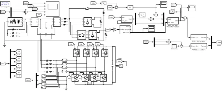
A simulation model for the three-phase four-leg PWM converter with the parameters shown in Table I has been
developed using MATLAB-Simulink. The objective is to verify the current harmonic compensation
effectiveness of the proposed control scheme under different operating conditions. A six-pulse rectifier was used
as a nonlinear load.
Discrete, Ts = 5e-005 s.
powergui dq0 sin_cos abc dq0_to_abc Transformation abc sin_cos dq0 v v v v +-v + -A B C + -A B + -A B C + -N A B C A B C a b c Three-Phase Breaker
A B C
a b c
A B C a b c A B C a b c Signal(s) Pulses PWM Generator1 Signal(s) Pulses PWM Generator g C E g C E g C E g C E g C E g C E g C E g C E Sc Sb1 Sb Sa1 Sa gate Goto4 Iln Goto3 Io_Ref Goto2 Sn Sn1 Sc1 Vabcn Vdc Goto 0 -K-Iou Isabc Isabc Vdc Vsabc ILabc Isabc Vdc Sn1 Sc1 ILabc Sb1 Sn Sc Sb Sa1 Sa gate Iln Isabc Vsabc Fo= 16Hz N= 2 Fo= 20Hz N= 2 PI i + -i + -i + -i + -i + -0 Constant1 162 Constant Breaker Vabc (pu) Freq wt Sin_Cos
119 | P a g e
0.5 0.55 0.6 0.65 0.7 0.75 0.8
-100 0 100
0.5 0.55 0.6 0.65 0.7 0.75 0.8
-10 0 10
0.5 0.55 0.6 0.65 0.7 0.75 0.8
-2 0 2
0 0.5 1 1.5
-1 0 1
0.5 0.55 0.6 0.65 0.7 0.75 0.8
-2 0 2
0.5 0.55 0.6 0.65 0.7 0.75 0.8
-10 0 10
0 0.5 1 1.5
-500 0 500
Time
Fig.8. Source voltage (Vsabc), Load current (ILabc), Filter output currents (Icabc), load neutral current (ILn),
system neutral current (Isn), system currents (Isabc), dclink voltage (Vdc)
In the simulated results shown in Fig.7, the active filter starts to compensate at t = t1. At this time, the active
power filter injects an output current iou to compensate current harmonic components, current unbalanced, and
neutral current simultaneously.
Discre te , Ts = Ts s.
powe rgui dq0 sin_cos abc dq0_to_abc Transformation abc sin_cosdq0
v + -v + -v + -v +
-v + -A B C + -A B C + -N A B C A B C a b c
A B C
a b c
A B C a b c A B C a b c
Signal(s) Pulse s
PWM Generator1
Signal(s) Pulse s
PWM Generator g C E g C E g C E g C E g C E g C E g C E g C E Sc Sb1 Sb Sa1 Sa gate Goto4 Io_Ref Goto2 Sn Sn1 Sc1 Vabcn Vdc Goto 0 -K-Isabc Isabc Vdc Vsabc ILabc Isabc Vdc Sn1 Sc1 ILabc Sb1 Sn Sc Sb Sa1 Sa gate Isabc Vsabc Fo= 16Hz N= 2 Fo= 20Hz N= 2 PI i + -i + -i + -i + -0 Constant1 162 Constant Vabc (pu) Fre q wt Sin_Cos
Fig . 9. Simulation model of proposed system
1.2 1.25 1.3 1.35 1.4 1.45
-100 0 100 V s a b c
1.2 1.25 1.3 1.35 1.4 1.45
-10 0 10 Is a b c
1.2 1.25 1.3 1.35 1.4 1.45
-10 0 10 IL a b c
1.2 1.25 1.3 1.35 1.4 1.45
-2 0 2 Is a b c
1.2 1.25 1.3 1.35 1.4 1.45
162 164 166 Time V d c
Fig .10 Source voltage, Load current, Filter output currents, load neutral current, system neutral current,
120 | P a g e
VII. CONCLUSION
Improved dynamic current harmonics and a reactive power compensation scheme for power distribution systems
with generation from renewable sources has been proposed to improve the current quality of the distribution
system. Advantages of the proposed scheme are associated with its simplicity, modeling, and implementation.
The use of a predictive control algorithm for the converter current loop proved to be an efficient solution for
active power filter applications, improving current tracking capability, and transient response. Simulation results
have proved that the proposed predictive control algorithm may be a good various to classical linear control
methods. The predictive current control algorithm may be a stable and robust solution. Simulation results have
shown the compensation effectiveness of the proposed active power filter.
REFERENCES
[1] J. Rocabert, A. Luna, F. Blaabjerg, and P. Rodriguez, “Control of power converters in AC microgrids,”
IEEE Trans. Power Electron., vol. 27, no. 11, pp. 4734–4749, Nov. 2012.
[2] M. Aredes, J. Hafner, and K. Heumann, “Three-phase four-wire shunt active filter control strategies,” IEEE
Trans. Power Electron., vol. 12, no. 2, pp. 311–318, Mar. 1997.
[3] S. Naidu and D. Fernandes, “Dynamic voltage restorer based on a fourleg voltage source converter,” Gener.
Transm. Distrib., IET, vol. 3, no. 5, pp. 437–447, May 2009.
[4] N. Prabhakar and M. Mishra, “Dynamic hysteresis current control to minimize switching for three-phase
four-leg VSI topology to compensate nonlinear load,” IEEE Trans. Power Electron., vol. 25, no. 8, pp.
1935– 1942, Aug. 2010.
[5] V. Khadkikar, A. Chandra, and B. Singh, “Digital signal processor implementation and performance
evaluation of split capacitor, four-leg and three h-bridge-based three-phase four-wire shunt active filters,”
Power Electron., IET, vol. 4, no. 4, pp. 463–470, Apr. 2011.
[6] F. Wang, J. Duarte, and M. Hendrix, “Grid-interfacing converter systems with enhanced voltage quality for
microgrid application; concept and implementation,” IEEE Trans. Power Electron., vol. 26, no. 12, pp.
3501– 3513, Dec. 2011.
[7] X.Wei, “Study on digital pi control of current loop in active power filter,” in Proc. 2010 Int. Conf. Electr.
Control Eng., Jun. 2010, pp. 4287–4290.
[8] R. de Araujo Ribeiro, C. de Azevedo, and R. de Sousa, “A robust adaptive control strategy of active power
filters for power-factor correction, harmonic compensation, and balancing of nonlinear loads,” IEEE Trans.