Energy storage
T. M. Taylor
CERN - Geneva, Switzerland
1. – Fundamentals
There are several ways to store energy. When applied to electrical energy, they must be chosen to take into account the location and cost of the storage, and its required duration.
– potential energy m·g·h,
– kinetic energy 1/2m·v2,
– magnetic energy τ(B2/2μ0)dτ = 1/2L·I2,
– capacitive energy 1/2C·V2,
– chemical energy reversible reaction,
wheremis mass (kg),his height (m),vvelocity (m/s),Linductance (H),Icurrent (A),C capacitance (F),V voltage (V), andgis the Earth’s gravitational constant (∼9.81 N/kg) andμ0the permeability of free space (4π10−7H/m).
τ represents the volume integral. In order to appraise and compare systems, it is necessary to understand the concepts ofentropy and exergy, and when evaluating costs to take into account that of ancillary equipment and the value of occupied space. Associated with each method there is the energy density and the cycle efficiency. Processes that involve the conversion of heat into motive power or electricity are subject toCarnot efficiency. Reference [1] is a good modern source book on the subject of storing energy, with special reference to renewable energy.
2. – Potential energy
Pumped water is the traditional way of storing electrical energy (PHS or PHES), particularly in places where hydroelectric power is significant (e.g. the Alps). When power is cheap, pump water into the elevated lake (see fig. 1). For example, a mountain lake of 10 km2, 1 km above another lake, will store about 1011 J (= 102GJ) per m of depth. As 1 MWh = 3.6 GJ, this is equivalent to 27.8 MWh, and assuming a roundtrip efficiency of 75% (industry standard) this gives about 100 MWh per 5 m depth of water. At this scale the energy storage is clearly in the suppliers’ hands.
Fig. 1. – Schematic of pumped water energy storage.
energy stored would be about that one could store in 2 car batteries! Hardly appealing, except in very particular circumstances. . . .
Pumped storage is presently by far the largest form of energy storage capacity for grids, and accounts for 95% of storage installations worldwide, with a capacity of about 300 GWh, and a generating capacity of>150 GW. There is a wealth of knowledge about the associated engineering [2].
An idea being pursued is that of an underwater reservoir where energy is stored by pumping water out of a spherical shell and recovered by letting the pressure of the surrounding water drive the turbine as it flows into the sphere. The advantages of this method are that only cables are required (no pipes) and space is not a problem. A trial has been successfully undertaken in Lake Constance [3], and it is confidently predicted that if multiple units were to be mass produced and installed close to big cities on coasts close to deep water (e.g.in Japan), such systems could store hundreds of GWh, and be cost competitive.
Other ways to use potential energy includecompressed air (or nitrogen),liquefied gas (air, nitrogen), andheat.
Pumped heat (thermal energy) storage (TES) is another method [7]. This uses two large steel tanks filled with mineral particulates (gravel). The system is charged by compressing argon at ambient temperature to 12 bar, heats to 500◦C, storing the energy used to power the motor generator (A monatomic gas (e.g. argon) is used as the working gas: it heat/cools more than air for the same pressure change, reducing storage cost). Argon is injected at the top of tank 1, slowly descends, exits at the bottom at room temperature (RT) and ∼12 bar, whence it passes to the expander, the temperature is reduced to−160◦C and it is injected into the bottom of tank 2 to exit at the top at RT. To recover the energy, the process is reversed. The argon is cooled to−160◦C in tank 2, it is then compressed to 12 bar (at RT) and sent to tank 1 where it is heated and the hot gas expanded gas via a turbine to generate power. The round trip efficiency of such a process is about 75%.
An alternative way to store thermal energy isliquid air energy storage(LAES) (also referred to as cryogenic energy storage (CES)). The charging system is an air (or N2) liquefier, using electrical energy (700 litres of ambient air become 1 litre of liquid air). The liquid air is stored in an insulated tank at low pressure, which functions as the energy store. Such equipment is used globally for bulk storage of liquid N2, O2and LNG and can hold GWh of energy. When power is required, liquid air is drawn from the tank(s) and pumped to high pressure. The air is evaporated, is superheated to ambient temperature and the warm high-pressure gas drives a turbine. A proprietary high-grade cold store, to be used later during the liquefaction process to enhance efficiency, captures the cold from the expansion. An example of a pilot system of this type is a 2.5 MWh installation in the UK [8].
3. – Kinetic energy
for use in trains that can deliver a burst of power of up to 300 kW [9]. The 375 mm diameter flywheel for such a system weighs 350 kg and rotates at 5000 to 10000 rpm: the mass of a complete system is 1.5 t.
At another scale are the large motor generators used in conjunction with powering the pulsed magnets of particle accelerators and tokamaks. The magnetic field in the 101 bending magnets of the CERN proton synchrotron (CPS) is cycled between 0.11 T at injection energy of the protons (1.4 GeV) to 1.25 T at top energy (26 GeV). The repetition time is 2.4 s. About 6 to 8 million cycles are executed each year. The impedance or the magnets string is 0.32 Ω and 0.9 H and the current at top energy is 5.5 kA. The active power for operating this string peaks at 40 MW at the end of the acceleration, at which time the increase in stored magnetic energy also reaches a maximum. In order to avoid perturbing the network, from the start, in 1959, aflywheel motor-generator system was used (fig. 2). The mass of the rotor was 90 t, and the maximum stored energy 233 MJ (@ 1000 rpm). The speed of the rotor decreases by 5% during ramp-up while the generator absorbs 6 MW; during ramp-down, the stored energy flowing from the magnets, peaking at 12 MJ, reaccelerates the rotor to nominal speed [10]. The operation of the accelerator relied on this device working: it obviously contained moving parts, so preventive maintenance was crucial. This was outsourced, but over the years it became increasingly difficult to find a competent supplier, and the device was recently replaced by a capacitor bank (see below). The world’s largest such device supplied the toroidal magnet of the JT-60 tokamak. The 650 t flywheel, built from 6 carbon steel disks, is installed in a 12 m diameter and 12 m deep vertical shaft, and features a water-cooled heat exchanger [11]. Once every 10 minutes the device can generate a current of 6.9 kA at 18 kV, with a discharge energy of 4 GJ. As for the case of the CPS machine, the main purpose of such a system was to avoid periodic disruptive overload of the network, rather than to store energy per se. However, with the advent of more efficient batteries and super-capacitors, interest in the use of flywheels is on the wane.
4. – Energy storage in magnets
Fig. 2. – The CERN PS motor generator (photo CERN).
use ofsuperconducting magnetic energy storage (SMES), and the corresponding design of suitable magnets, with regard to
– use in conjunction with medical accelerators (10 MJ scale),
– use in conjunction with large accelerators (100 MJ scale).
SMES system at the beginning of the planning of construction. Magnet designers should pay attention and come up with a cut-price solution.
Another study [13], also in Japan, addressed the opportunity of using SMES on a larger scale (as an alternative to the flywheel solution for the energy upgrade of the J-PARC accelerator). For this accelerator, the energy to be delivered by SMES is 21 MJ. If it is assumed that 30% of the capacity of the SMES system is used for this purpose, the system must be designed to store 70 MJ. The study proposed using a modular solution —as there are six power converter modules, there would be six SMES modules, affording some economy of scale. An economic magnet design based on the use of Nb-Ti superconductor in the form of a flat cable (as used for the LHC dipoles) and suitable for series production was also proposed.
5. – Energy storage in capacitors
This is a dynamic sector, due to the development of self-healing components for moderately high voltage applications. The public is becoming aware of the possibilities thanks to the incorporation in “stop-start” in cars, where it reduces the peak demand on the battery when starting the engine. Its use is attractive due to its passive nature (no moving parts, no cryogenics), and the mass production of components. But the energy density is low, even compared with that of batteries, so one needs plenty of space, and there is some concern that the components may be delicate. The nature of this form of energy storage is such that it is often assimilated into the category of batteries.
If it fails, a capacitor will fail in one of three ways:
– Capacitor short-circuit.
The capacitor gets short-circuited with very high loss factor. It occurs when the dielectric breaks down completely and film melts. This is severe case.
– Capacitor open-circuit.
The capacitance value drops by more than 30%. There is no visible damage to the film metallization. This failure is due to poor metal spraying, or to defective welding of terminals.
– Degradation of capacitance.
There can be two reasons for this: excessive concentration of self-healing at the weak spots of the dielectric, leaving other areas unaffected; metal oxidation.
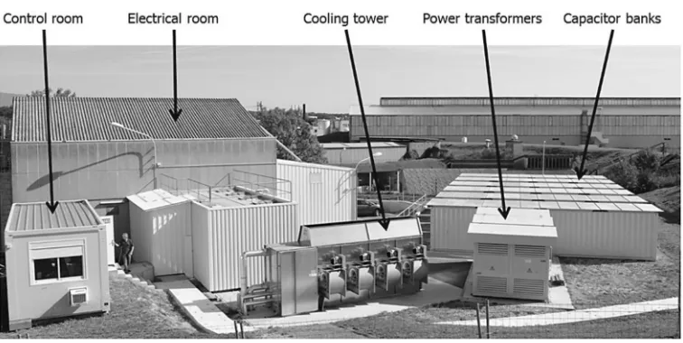
Fig. 3. – Capacitor energy storage for powering the CERN PS (photo CERN).
– capacitors support practically unlimited discharge cycles,
– a modular solution could be based onindustrial components.
The capacitors are part of a new system, in operation since 2011, which integrates three functions: it converts AC current from the network to DC current as required; it charges the capacitors with energy for pulsing the magnets; when the energy is not needed it is stored in the capacitor banks. The six capacitor banks are connected to the magnet string via six DC/DC converters, which precisely control current and voltage in the magnet circuit, independent of the voltage of the capacitors. The capacitor voltage decreases from 5 kV to 2 kV during the ramping to top energy and increases again to 5 kV during ramp-down. The energy density is low and the banks of capacitors for this system fill six standard 40-foot shipping containers as shown in fig. 3. This exhibits the principal disadvantage of capacitors for storage of large quantities of energy: the very large footprint. In addition, while the capacitors are expected to be reliable and long-lived, one has to consider the reliability of the necessary ancillary equipment. However, as all the components are of an industrial nature, with proper attention to quality control, these issues should be soluble.
6. – Chemical energy with reversible reaction. Batteries
are even getting interested (note the deal between TESLA and an Australian producer). Batteries are in the news —especially for application to cars, stimulated by the real-ization that it could be envisaged to replace the internal combustion engine reducing pollution in urban centres and possibly reducing the associated production of CO2, with its suspected impact on climate change. The vigorous development, increasing demand, and competition, is leading to improved performance and reductions in cost that when extrapolated support the interest in the field. Reported problems due to volatility of material cost should prove to be temporary. The major remaining issues are related to lifetime and reliability.
What is a battery? A device that converts chemical energy into electrical energy. It features a positive terminal (anode), a negative terminal (cathode), separated by an electrolyte that allows ions to move between the electrodes, giving rise to the flow of current. Just as for the other energy storage systems described here, this is not a new idea: Alessandro Volta developed the first battery in 1800. However, advances in tech-nology have led to improved output and reliability of rechargeable battery systems, and economies of scale have led to cost reduction and ever more applications.
– Lead-acid battery.
This has been (and still is) a “workhorse” rechargeable battery. It is based on mature technology, is mass-produced, and its primary component (lead) can be recycled. However, it is heavy, has a relatively short life (∼5 years), and rather poor storage density. During the charging cycle hydrogen is produced, which can also be a problem. Most of the other batteries discussed here feature solid-state electrolytes.
– Lithium-ion batteries (R&D in 1980s, commercialized in 1991 by Sony and Asahi Kasei).
a drawback. That aspect will need to be substantially improved if one hopes to persuade the networks to invest in this technology.
– Nickel-cadmium (Ni-Cd) batteries (in production since 1910).
The advantage of this type with respect to lead-acid batteries are longer life, near maintenance-free operation, low but acceptable energy density. Historically such batteries have been less costly than lithium (due to long manufacturing experience), but this advantage is now declining. This type of battery has long been used in energy storage systems.
– Nickel metal hydride (NiMH).
This is the type of battery that Toyota uses for its hybrid cars [17]. The traction battery is a sealed 28 module pack storing 1.31 kWh (201.6 V, 5.6 Ah) made by Panasonic. Energy density is 46 Wh/kg, maximum output power 1.3 kW/kg. Over 2 million Priuses with such batteries have been sold, but Toyota now equips higher end vehicles with 15 kg lighter Li-ion packs. NiMH batteries are said to last about 10 years, and this type of battery is also proposed for domestic use, being cheaper than Li-ion alternatives (but heavier and takes more space).
– Sodium-sulphur (Na/S) batteries (1960, Ford; now NGK, Japan).
These batteries operate at 300 to 350◦C, so are not likely to appear in homes. The anode is molten sulphur, the cathode is molten sodium and the electrolyte is sodium alumina [18]. The battery exhibits a remarkable round-trip efficiency (up to 90%), and is widely used for energy storage in Japan (190 sites). The largest installation can store 245 MWh and deliver 34 MW.
Another type of battery is theflow battery [6]. This is a rechargeable battery where energy is provided by two chemical components, dissolved in liquids, separated by a membrane, making it similar to a fuel cell. The main discerning feature is that immediate recharge is possible by replacing electrolyte. It is nice to know that the technology exists, and there are certainly uses for this kind of battery.
TableI. –Comparison of the approximate energy density of common materials and devices.
Stored energy
Material/device Volume Specific Notes
(kWh/L) (kWh/kg)
Gasoline(a) 9 13 Diesel and kerosene similar
LNG(a) 6 14 Propane, butane similar
Coal(a) 8 10 Especially dirty
Ethanol(a) 6 7 As a fuel
Wood(a) 3.5 4.5 Methanol and biomass similar
Liquid H2(b) 2.5 39 Needs a cryostat
H2 @ 700 bar(b) 1.5 39 Needs a pressure vessel
H2 @ 1 bar(b) 0.003 39 Voluminous, highly combustible
Flywheel 0.2 0.15 Mass is tripled by containment gear
Liquid air 0.07 0.06 Needs a cryostat. Voluminous
Lithium-ion battery 0.5 0.3 Better versions in development
NiMH battery 0.25 0.1 As used in the Toyota Prius
Ni-Cd battery 0.15 0.07 Mature technology, robust
Lead-acid battery 0.15 0.05 Mature technology, recyclable
superconducting magnet 0.03 0.02 5 T. Needs a cryostat. Long life
Super-capacitor 0.015 0.01 Self-healing propylene. Long life
(a)
Efficiency of producing electricity via turbines powered by burning these materials: 30%.
(b)
Efficiency about 30% if used for heat, and 40–70% if used in a fuel cell, not counting the energy needed to produce the hydrogen (unless it is derived from non-renewable sources).
7. – Energy density
This table is very instructive: when looking at the whole picture the convenience and cost efficiency of natural gas-powered production of electrical, and of vehicles using the internal combustion engine cannot be denied. Moving towards a system where a significant fraction of energy come from renewable sources will require an immense effort on the part of society. It is perhaps out-of-fashion, but from the point of view of reducing pollution and production of greenhouse gases, it would be probably be preferable to replace the unavoidable fraction of power delivered from non-renewable sources by nuclear power, preferably based on the intrinsically safe thorium technology [20].
In the case of electric vehicles (EV), it is not obvious that one should aim at storing sufficient electrical energy in batteries for driving 500 km, when for 50 weeks of the year the average daily drive is 65 km. A plug-in hybrid with a range of 100 km fully electric would be lighter and cheaper, and require less infrastructure. Moreover, if in any case we admit that some power will come from fossil fuel this could as well be burnt in an internal combustion engine as in a power station. Alternatively, one could consider using an on-board generator to charge the battery, and which could be installed temporally for long trips.
8. – Are there alternatives to energy storage (ES)?
The reasons for needing to store energy, readily available in the form of electricity, are:
– To integrate renewable energy into existing networks and energy independence.
ES supports the integration of renewable power. By reducing the load on fossil-fuel generation ES helps cut emissions —but more capacity to meet peak demand is required.
– To reduce risk associated with power outages.
Today’s electricity grid is vulnerable to threats from nature, terrorists, and acci-dents.
– To save consumers money.
Energy storage (ES) lets customers avoid premium pricing during times of peak demand.
– For the economy in general.
In addition to reducing economic losses from major and minor annual outages, ES will be a critical technology in the electricity grids of the future, and will thereby create economic activity. In this context it is sometimes said that a next-generation smart grid without energy storage would be like a computer without a hard drive.
capacity to satisfy all demands at all times can be addressed in other ways. The hard-nosed market-based approach would be to accept some short periods (hours, days?) of power outage: this also provides an incentive to adopt local energy storage, at the personal or communal level. A pure market-based approach would also lead to massive increase of tariffs during bad peaks and serve to “train” consumers to adjust consumption. Or one could use technology to adopt a socially more acceptable approach,e.g.to install long distance power transmission lines to flatten demand by distributing consumption, addressing daily peaks by delivering surplus power to locations in other time zones. This can be done using either high voltage DC power transmission (800 kV overhead lines are in operation in Korea and China, but problematic in Europe and the USA, more prone to “not-in-my-backyard” (NIMBY) problems), or high current DC power transmission via superconducting linkswhich can provide virtually loss-free transmission of GW proportions. Such links can be buried like pipelines. As an example, CERN, needing to power its high current magnet systems from distant radiation-free locations of power converters, has developed a magnesium diboride (MgB2) superconductor and 20 kA cable for its own use [21]. Further to the CERN initiative, MgB2 technology was proposed by Prof. Carlo Rubbia, erstwhile scientific director of the Institute for Advanced Sustainability Studies (IASS) in Potsdam, for an innovative transmission line for long-distance transport of power generated from renewable sources, and which has since been taken up by the BEST PATHS European project [22]. The relatively new MgB2 superconductor, which could be cheaper than other superconducting materials if it were to be manufactured on a large scale, has a critical temperature of 39 K. This means that it can be used cooled to 20 to 25 K, presenting a lower cryogenic load than regular Nb-Ti superconductor that requires 4.5 K, and liquid hydrogen could be used as the coolant rather than the more expensive liquid helium. One could even envisage combining the transmission of liquid hydrogen in the pipeline to increase the transfer of energy. As well as being used to connect renewable energy sources (wind, PV) in flat areas with existing energy storage facilities such as dams in mountainous areas, electrical utilities can call upon superconductivity to minimize costs in other ways,e.g.to improve the efficiency of power generation from wind by using superconducting generators.
9. – Impact of markets and regulation on the development of energy storage
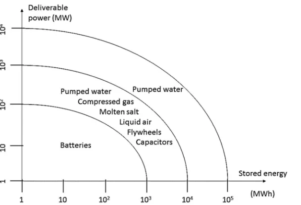
Fig. 4. – Comparative overview of the potential of energy storage methods.
on hold. This is in contradiction with the most pressing societal needs,i.e.to increase storage capacity. By far the most efficient way to store large quantities of electrical en-ergy, at the level of the network, is by the pumped water method. It is crucial that this distortion be recognized and the market regulated to counteract the effect, by coupling the production of peaky electrical power with a requirement to invest in energy storage, to render the power less peaky (e.g.by taxing surplus power and using the proceeds to invest in pumped water storage). In addition, individual households and communities should be encouraged to invest increasingly in battery storage, as the price of such equip-ment comes down, and one could probable use efficiently the storage capacity of batteries in electric vehicles when they are not being used (which is most of the time. . . ). These batteries could be charged during the daytime when power from PV parks is (should be) cheap, to be used in the evening or early morning. However, this will require that the distributors of power, which presently profit inordinately by charging customers histor-ical daytime rates, pass on the low prices. As the distributors usually benefit from a monopoly position, this will require some regulation.
10. – Comparative overview of the field of energy storage
NiMH will continue to be used because of the long experience with production and application, but the market for these types is unlikely to expand. For storage of large quantities of electrical energy, the traditional method of pumped water, either between reservoirs or in and out of pods located in trenches under the sea, will continue to be the preferred technology. It is to be hoped that ways will be found to couple this resource to energy derived from wind and PV in such a way as to enhance its overall quality. The other methods referred to in this report will continue to have niche applications, but it seems unlikely that in the near future they will rise to challenge the new generation of batteries and the established dominance of pumped water storage.
11. – Conclusion
From the very beginning, the electrical grid system designers have been aware of the importance of finding ways to store energy. Most of the methods have been in use for quite a long time, but (apart from pumped water) on a relatively small scale. This was also because fossil fuel is cheap. But the realization that the side effects of massive use of fossil fuel (pollution, possible effect on climate change, and eventually limited supplies), the world has woken up to the fact that we should move to using renewable sources,e.g.wind, PV and biomass. Electrical power from wind and PV fluctuates widely, focusing on the importance of storage, but electrical power and electronic engineering has advanced to make DC-DC, AC-DC and DC-AC conversion highly efficient, and with components readily available many new possibilities are opening up. Economies of scale have made generation of power from renewable sources competitive. This is already a highly dynamic field of activity. According to market research, the energy storage market is set to rise to an annual installation size of 6 GW in 2017 and over 40 GW by 2022, from a base of 0.34 GW installed in 2012 and 2013. Over a thousand companies serve the energy storage industry. Pumped water, heat, flywheel, battery and capacitor systems are operating today in the competitive ancillary services power market with fast and accurate response to distribution signals. The market for solar panels —which was less than $200 million in 2012— will be about $19 billion in 2017, and much of the energy produced will have to be stored- at least for a few hours. Energy storage is already big business, and it is set to become much bigger still. One should nevertheless pay attention to other technologies that could affect storage requirements,e.g.by increasing long distance power transmission capacity and smartening the grid.
REFERENCES
[1] Letcher T. M.,Storing Energy(Elsevier) 2016.
[2] Jones G. M.(Editor),Pumping Station Design(Butterworth-Heinemann, Elsevier) 2011.
[3] https://www.energiesystemtechnik.iwes.fraunhofer.de/.
[4] Lockerby R. W.,Compressed Air Energy Storage (Vance Bibliographies) 1983.
[5] Breeze P.,Solar Power Generation(Elsevier) 2016, p. 39.
[7] Dinc¸er I.andRosen M. A.,Thermal Energy Storage: Systems and Applications(Wiley)
2011.
[8] http://www.highview-power.com/technology/. [9] http://elytt.com/#!modules/pages/home.
[10] Burnet J.-P., Capacitive energy storage replaces flywheel, p. 68 in
http://www.worldscientific.com/worldscibooks/10.1142/9921#t=toc.
[11] Matsukawa T.et al., “A 215 MVA flywheel motor-generator with 4 GJ discharge energy
for JT-60 toroidal field coil power supply system”,IEEE Trans. Energy Conversion,EC-2, No. 2 (1987) 262.
[12] Sato H. et al., “Application of energy storage system for the accelerator magnet power
supply”,Proc. Int. Particle Accelerator Conference (IPAC-10)(2010) p. 3236.
[13] Sato H., Shintomi T.et al., “Electric power compensation of the large scale accelerator
using SMES”,IEEE Proc. Particle Accelerator Conference (PAC’07)(2007) p. 239. [14] Fahrni C., Burnet J. P. et al., “A multilevel power converter with integrated storage
for particle accelerators”, inProc. Power Converter Conference (PCC’07)(2007) p. 1480. [15] Menictas C., Skyllas-Kazacos M.andLim T. M.(Editors),Advances in Batteries for
Medium- and Large-scale Energy Storage(Woodhead Publishing, Elsevier) 2015. [16] http://batteryuniversity.com/learn/article/types of lithium ion. [17] http://www.hybridcars.com/hybrid-car-battery/.
[18] Sudworth J. L. andTilley A. R.,The Sodium Sulphur Battery (Chapman and Hall,
London) 1985.
[19] Hirscher M.,Handbook of Hydrogen Storage (Wiley-VCH) 2010.
[20] Revol J.-P., Bourquin M. et al. (Editors), “Thorium Energy for the World”, Proc.
ThEC Conference, Geneva, Switzerland, October 2013 (Springer, Berlin) 2013.
[21] Ballarino A., Final design report,CERN-ACC-2015-0134 (2015); https://cds.cern.