Comparison and Analysis of Microstrip Low Pass Filter
using DGS technique for WLAN Applications
Aanshi Jain
1, Anjana Goen
21
M.Tech Scholar, Dept. of ECE, Rustam Ji Institute of Technology, Tekanpur, Gwalior, (India)
2Associate Professor, Dept. of ECE, Rustam Ji Institute of Technology, Tekanpur, Gwalior, (India)
ABSTRACT
The Butterworth low pass filter (LPF) with defected ground structure (DGS) is studied and simulated for WLAN
Applications. Also an elliptical low pass filter with defected ground structure is simulated for WLAN Applications.
Both the low pass filters design are simulated on FR4 substrate of relative permittivity is 4.3 and thickness 1.6mm.
Calculation and comparison of the response of both low pass filters (LPF) with defected ground structure (DGS)
was done. Results are simulated using computer simulation technology software (CST).
KEYWORDS
BSF (Band Stop Filter), CST (Computer Aided Technology), DGS (Defected Ground Structure)
,
EBG
(Electromagnetic Bandgap)
,
PBG
(Photonic Bandgap)
.
I.
INTRODUCTION
Microstrip filters are very demanded because of its ease in fabrication, small size, and low cost, light weight in
cellular mobile phone industry and in many integrated circuits. Many communication devices need a small size filter which can easily be fit inside the body of cellular phone, although attempt is always continuing to achieve Sharp cutoff, by making defect in its ground called the defect ground structure. It has been designed a simple microstrip filter for WLAN application. [1]
Also, Defected ground structure for microstrip line was most common topic for research at recent year. They are giving a lot of different structure for implementing DGS [2]. Microwave filter designs have been at the forefront of research in both industry and academia due to increasing specification levels and demand for advanced communication systems.
and direction, and most important function of these structures is the filtering of frequency bands, and harmonics of the filter in microwave circuit.
The realizable filters that are in common use are Butterworth filter, Chebyshev filter and Bessel filter. Conventional micro-strip low pass such as stepped-impedance filters, semi lumped element filters are widely used in many RF/microwave applications.
In general, lowpass filters involves two main steps for the design of microstrip low pass filters. The first one is to select an appropriate lowpass prototype, choice of the type of response, including passband ripple and the number of reactive elements, will depend on the required specifications [6-10]. The next main step in the design of microstrip lowpass is to obtained a suitable lumped-element filter design. Filters are to find an appropriate microstrip realization that approximates the lumped element filter.
STEPPED
IMPEDANCE
BUTTERWORTH
LOW
PASS
FILTER
In stepped impedance Butterworth LPF with L-C ladder type LPF with open circuited stub having frequencies of infinite attenuation at f = infinite. To find sharper cutoff for a given number of reactive elements it is desirable to use filter structure giving infinite attenuation at finite frequencies. Figure 1 shows a cascaded structure of alternating high- and low impedance transmission lines shows general structure of the stepped-impedance Butterworth lowpass microstrip filters, which use a. These are much shorter than the associated guided- wavelength, so as to act as semi lumped elements [8]. The low-impedance lines act as shunt capacitors whereas the high-impedance lines act as series inductors . Therefore, this filter structure is directly realizing the L-C ladder type of lowpass filters of figure 2.
Figure 1:
General structure of the stepped-impedance Butterworth lowpass microstrip filter.
ELLIPTICAL LOW PASS FILTER
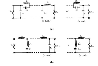
Figure 3 illustrates two commonly used network structures for elliptic function lowpass prototype filters. In Figure 3(a), the series branches of parallel-resonant circuits are introduced for realizing the finite-frequency transmission zeros, since they block transmission by having infinite series impedance (open-circuit) at resonance. The gi for odd i(i= 1, 3, · · ·) represent the capacitance of a shunt capacitor For this form of the elliptic function lowpass prototype [Figure 3(a)],, gi for even i(i = 2, 4, · · ·) represent the inductance of an inductor, and the primed for even i(i = 2, 4, · · ·) are the capacitance of a capacitor in a series branch of parallel-resonant circuit. The series-resonant circuits are used for implementing the finite-frequency transmission zeros for the the response that is equal-ripple in both the passband and stopband and in the elliptic function response is used for the dual realization form in Figure 3(b). The transfer function for this type of response is
(1) For the dual realization form in Figure 3(b), the shunt branches of series-resonant circuits are used for
implementing the finite-frequency transmission zeros, since they short out transmission at resonance. In this case, referring to Figure 3(b), gi for odd i(i = 1, 3, · · ·) are the inductance of a series inductor, gi for even i(i= 2, 4, · · ·) are the capacitance of a capacitor, and primed for even i(i = 2, 4, · · ·) indicate the inductance of an inductor in a shunt branch of series-resonant circuit. Again, either form may be used; because both give the same response [11-12] shunt branches, since them short out transmission at resonance. In this case, referring to Figure 3(b), gi for odd i(i = 1, 3, · · ·) are the inductance of a series inductor, gi for even i(i= 2, 4, · · ·) are the capacitance of a capacitor, and primed for even i(i = 2, 4, · · ·) indicate the inductance of an inductor in a shunt branch of series-resonant circuit. Again, either form may be used, because both give the same response [11-12]
(a)
Figure 3:
Lowpass prototype filters for elliptic function filters with (a) series parallel-resonant
branches, (b) its dual with shunt series-resonant branches.
II.
PROCEDURE
LPF was design at the cut off frequency of fc in GHz and formula which is used for the design of LPF is
Synthesis of W/h
(2)
With
(3)
Where Zc=Zo = 50Ω and εr (dielectric constent) = 4.4, W= width, h= height of dielectric which is taken
as 1.6mm.
Effective dielectric constant of dielectric material given by equation (13) and (14)
For W/h ≤ 1:
(4)
For W/h>1
(5)
Whereas guided wavelength is given by equation (6)
εre = Effective dielectric constant
Values of inductor and capacitor are given by
(7)
For i = 1, 2, 3, ... , 6.
Calculation of length of inductor and capacitor is done using formula
(8)
(9)
The proposed design of 3
rdorder Butterworth low pass filter shown in Figure 4.
(a)
(b)
Figure 4:
(a) front view of proposed designed micro-strip 3rd order Butterworth stepped impedance
function LPF (b) Back view of ground structure of the designed micro-strip 3
rdorder Butterworth
stepped impedance function LPF.
.
Figure 5:
Simulated graph of 3
rdorder stepped impedance Butterworth Low pass filter
The proposed design of the 5th order stepped impedance Butterworth Low Pass Filter is shown in the Figure 6. FR4 lossy material with dielectric constant of 4.4, substrate height of 1.6mm and loss tangent 0.02 was used in the designing of low pass filter. A rectangular shaped slot of dimension 6mm X 4mm is introduced in the centre of the ground plane which shows the ground as defected. One rectangular shaped slot of equal size is introduced in the both capacitor part (C2 & C4) of the proposed design of microstrip Butterworth low pass filter. Dimension of rectangular shaped slots is 0.7mm X 6mm and it is placed form the 0.4mm far away from the inductor part (L1 & L5) of the design.
(b)
Figure 6:
(a) Front view of proposed designed 5
thorder microstrip stepped impedance butterworth
function LPF.
(b) Back view of ground structure of the designed microstrip stepped impedance function LPF.
Figure 7:
Simulated result of stepped impedance 5
thorder Butterworth low pass filter with DGS.
From the response shown in figure7, it is clear that the cut-off frequency is found to be 5GHz for stepped-impedance low pass filter. Hence stepped impedance low pass filter is capable of passing the frequency less than 5GHz & reject the frequency after 5GHz.
(a)
(b)
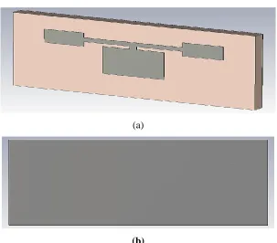
Figure8:
(a)Front View of Proposed 3rd order Elliptic Low Pass Filer (b)Back View of Proposed
3rd order Elliptic Low Pass Filer.
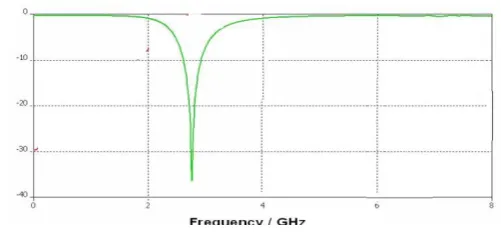
The simulated result of the 3rd order low pass Elliptical filter is shown in the Figure 9. The graphs were obtained after the simulation by CST software. This graph shows that the cut off frequency is at 5 GHz which means that the signals were passing before this frequency. Also after 5 GHz, the signal shows attenuation of –35 to –40 dB (means good stop band). Return loss before 5 GHz is below –10 dB which shows proper impedance matching.
Figure 9:
Simulated result of stepped impedance 3
rdorder Elliptic low pass filter using DGS.
The proposed design of elliptic - function low pass filter shown in Figure 10. The 5th order elliptic function low pass filter was
design using rectangular shape ground structure. The dimensions of the proposed low pass filter calculated at the center
frequency of 5 GHz using electromagnetic equations.
LPF is printed on the FR4 lossy substrate of dielectric constant 4.4, loss tangent 0.02 and thickness of 1.6mm with dimension of
(a)
(b)
Figure 10:
Proposed 5
thorder Elliptic Low Pass Filer.
(a)
Front View (b) Back View
The simulated result of the 3rd order low pass filter is shown in the Figure 5.11. The graphs obtain after the simulation by CST Software. This graph shows the cut-off frequency is at 5 GHz means that the signals were passing before this frequency.
Figure 5.11:
Simulated result of 5
thorder Elliptical low pass filter with DGS.
III.
RESULTS
Table1:
COMPARISON BETWEEN 3
RDORDER BUTTERWORTH AND ELLIPTICAL LPFs
Table2:
COMPARISON BETWEEN 5
THORDER BUTTERWORTH AND ELLIPTICAL LPFs
V.CONCLUSION
The proposed designs was implemented and analyzed at the centre frequency 5GHz. A sharp rate of cutoff with reduce label of sideband fluctuation of the response achieved by introducing the slots in the ground plane structure which is behave as defected and two equal slots of rectangular shaped in the structure of stepped impedance microstrip low pass filter using Butterworth function . Also, 3rd order elliptic function microstrip low pass filter was achieved good return loss response at the centre frequency of 5 GHz.
It has been found that simulated results of 5th order microstrip Butterworth stepped impedance Butterworth low pass filter are in good agreement and better in comparison with proposed 5th order elliptic function microstrip low pass filter and also we can see from Table 1 that 3rd order microstrip Butterworth stepped impedance low pass filter are in good agreement and better in comparison with proposed 3rd order elliptic function microstrip low pass filter
REFERENCES
[1] Aanshi Jain, Anjana Goen, Neetendra Singh Dhakad, “An Overview of Elliptical Low Pass Filter by using
Defected Ground Structure Method”, Journal of Microwave Engineering & Technologies, Vol. 4, 2017.
TYPE
Insertio
n loss
directi
vity
Gain
efficien
cy
cutoff
Butterw
orth LPF
-38
5.38
7.8dB
21.22
2GHz
Elliptical
LPF
-37
4.782
6.082d
B
19.42
5 GHz
TYPE
Insertio
n loss
directiv
ity
Gain
efficienc
y
cutoff
Butterwort
h LPF
-60
4.87
3.52dB
11.55dB
5GHz
Elliptica-l
LPF
[2] Aanshi Jain, Anjana Goen, “Analysis and Design of Low Pass Filter by Using DGS for WLAN Application”,
International Journal of Advanced Research in Electrical, Electronics and Instrumentation Engineering, Vol. 6, 2017.
[3] R. Levy, R. V. Snyder, and G. Matthaei, “Design of microwave filters,” IEEE Trans. Microw. Theory Tech.,
Vol. 50, 2002.
[4] Li Zhongshen,“Design and Analysis of Improved Butterworth Low Pass Filter”The Eighth International
Conference on Electronic Measurement and Instruments ICEMI’2007.
[5] A. Casanueva, A. León, O. González, and A. Mediavilla, “A compact microstrip step-impedance
low-passfilter (SILPF) using complementary split ringresonators” IEEE 2009.
[6] Anju and Mamta Katiyar, “Design of Butterworth and Chebyshev 1 Low pass Filter for Equalized Group
Delay,” International Journal of Advanced Research in Computer Science and Software Engineering, Vol. 2,
2012.
[7] D. Kumar, A. De, “Effective Size Reduction Technique for Microstrip Filters”, Journal of Electromagnetic Analysis and Applications, 2013.
[8] Garvansh, Abhay Singh Kushwaha, Navita Singh, Arun Kumar,“Implementation of Stepped Impedance Low
PassMicrostrip Line Filter for Wireless Communication”International Journal of Advanced Research in
Computer and Communication Engineering Vol. 3,2014.
[9] Pozar, David M. “Microwave Engineering” 2nd Edition, USA: John Wiley &Sons/ D. M. Pozar, “Microwave
engineering newyork,” John Wile Yand Sons,Third Edition.
[10]Jia-Sheng Hong, M. J. Lancaste “Microstrip filters for
RF/MicrowaveApplication”AWiley-IntersciencePublivation book.
[11]Weng, L. H., Y. C. Gue, X. W. Shi, and X. Q. Chen, “An overview on defected ground structure,” Progress In
Electromagnetics Research B, Vol. 7, 2008
[12]Atallah Balalem, Ali, Jan Machac “Quasi-Elliptic Microstrip Low-Pass Filters Using an Interdigital DGS”IEEE 2007.
[13]CST (computer Simulation Technology) microwave software studio 2010
[14]Aanshi Jain, Anjana Goen,et.al; “An Overview of Elliptical Low Pass Filter by using Defected Ground