323
Recent Advances in Wireless Communication through
Implementation of OFDM-MIMO System
Geetanjali Mudaliar
Department of Electronics, P.G Scholar Email: [email protected]
Abstract--Wireless communication was conventionally implemented using Single Antenna at Transmitter and Single Antenna at Receiver. But this has the disadvantage of low spectral efficiency, low link reliability, medium data rates and the problem of frequency selective fading. This problem can be solved by using OFDM-MIMO Systems. The advantage of OFDM-OFDM-MIMO system is that it has the capacity of overcoming the frequency selective fading problem, high spectral efficiency, and low computational complexity. Orthogonal frequency division multiplexing (OFDM) is, it can transmit multiple Signal at a same time as is different from FDM Where selected frequency is allotted to each signal slots to be transmitted. This improves data rates in Wireless communication. OFDM may be combined with antenna arrays at the transmitter and receiver to increase the diversity gain and to increase the system capacity on time-variant and frequency-selective channels, resulting in a multiple-input multiple-output (MIMO) configuration.MIMO means multiple antenna at Transmitter and multiple antenna receivers side. This improves the capacity to overcome frequency selective fading. Thus OFDM combined with MIMO results in increased data rates and increased efficiency. In these proposed paper, system transmits a single signal using transmit diversity (TD) after that relay selection(RS) is done using Decode-and-forward (DF) protocol and Amplify-and–forward protocol(AF)and signal is transferred towards the receiver.
Index Terms- AF, DF, MIMO, OFDM, Relay selection (RS), Transmit diversity (TD).
1. INTRODUCTION
As the number of user in mobile communication ever increasing, it has become the major concern of mobile network. In mobile network, to extend coverage area, data rate, quality of service etc. is a major problem. Efficient mobile communication system requires significant performance in mentioned parameter. These rising demand of user cannot be fulfilled without further extending the existing system. In these respect, the paper below provide desirable characteristic well suited for mobile network application. In these proposed theory, we discuss OFDM,MIMO Systems and how these system transmit a single signal using transmit diversity concept ,after that relay selection using Decode-and-forward (DF) protocol and Amplify-and–Decode-and-forward protocol ,and the signal is sent towards receiver.
.
2.OFDM
Orthogonal frequency-division multiplexing (OFDM) is a method of encoding digital data on multiple carrier frequencies. OFDM has developed into a popular scheme for wideband digital communication, whether wireless or over copper wires, used in applications such as digital television and audio broadcasting, DSL Internet access, wireless
networks, power line networks, and 4G mobile communications.
Fig 1. A Simple OFDM
324 OFDM requires very accurate frequency
synchronization between the receiver and the transmitter; with frequency deviation the sub-carriers will no longer be orthogonal, causing inter-carrier interference (ICI) (i.e., cross-talk between the sub-carriers). Frequency offsets are typically caused by mismatched transmitter and receiver oscillators, or by Doppler shift due to movement. While Doppler shift alone may be compensated for by the receiver, the situation is worsened when combined with multipath, as reflections will appear at various frequency offsets, which is much harder to correct. This effect typically worsens as speed increases and is an important factor limiting the use of OFDM in high-speed vehicles. In order to mitigate ICI in such scenarios, one can shape each sub-carrier in order to minimize the interference resulting in a non-orthogonal subcarriers overlapping. For example, a low-complexity scheme referred to as WCP-OFDM (Weighted Cyclic Prefix Orthogonal Frequency-Division Multiplexing) consists in using short filters at the transmitter output in order to perform a potentially non-rectangular pulse shaping and a near perfect reconstruction using a single-tap per subcarrier equalization. Other ICI suppression techniques usually increase drastically the receiver complexity.
Fig.2 OFDM vs. FDM
3.MIMO System
Multiple-Input Multiple-Output (MIMO) technology is a wireless technology that uses multiple transmitters and receivers to transfer more data at the same time. All wireless products with 802.11n support MIMO, which is part of the technology that allows 802.11n to reach much higher speeds than products without 802.11n.
MIMO can be sub-divided into three main categories, precoding, spatial multiplexing or SM, and diversity coding.
Precoding is multi-stream beam forming, in the narrowest definition. In more general terms, it is considered to be all spatial processing that occurs at the transmitter. In (single-stream) beam forming, the same signal is emitted from each of the transmit antennas with appropriate phase and gain weighting such that the signal power is maximized at the receiver input. The benefits of beam forming are to increase the received signal gain, by making signals emitted from different antennas add up constructively, and to reduce the multipath fading effect. In line-of-sight propagation, beam forming results in a well-defined directional pattern. However, conventional beams are not a good analogy in cellular networks, which are mainly characterized by multipath propagation. When the receiver has multiple antennas, the transmit beam forming cannot simultaneously maximize the signal level at all of the receive antennas, and precoding with multiple streams is often beneficial. Note that precoding requires knowledge of channel state information (CSI) at the transmitter and the receiver.
Spatial multiplexing requires MIMO antenna configuration. In spatial multiplexing, a high rate signal is split into multiple lower rate streams and each stream is transmitted from a different transmit antenna in the same frequency channel. If these signals arrive at the receiver antenna array with sufficiently different spatial signatures and the receiver has accurate CSI, it can separate these streams into (almost) parallel channels. Spatial multiplexing is a very powerful technique for increasing channel capacity at higher signal-to-noise ratios (SNR). The maximum number of spatial streams is limited by the lesser of the number of antennas at the transmitter or receiver. Spatial multiplexing can be used without CSI at the transmitter, but can be combined with precoding if CSI is available. Spatial multiplexing can also be used for simultaneous transmission to multiple receivers, known as space-division multiple access or multi-user MIMO, in which case CSI is required at the transmitter. The scheduling of receivers with different spatial signatures allows good separability.
325 there is no channel knowledge, there is no beam
forming or array gain from diversity coding. Diversity coding can be combined with spatial multiplexing when some channel knowledge is available at the
transmitter interference then use serial to parallel convertor then use serial to parallel convertor. Then use FFT and one bit equalizer to minimize error then use signal demapper and parallel to serial convertor to get original signal. Thus obtain improved performance we design OFDM MIMO system.
4.OFDM-MIMO
Fig 4.Block diagram of OFDM-MIMO system
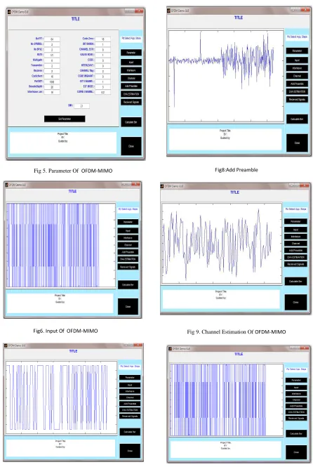
Let us estimate the output of OFDM –MIMO System in various stages. In fig 5 we have shown the
parameters which we have used in this project. It includes different parameters mentioned in fig below. The system consists of input where we provide input waveform .These input waveforms are randomly
[image:3.595.200.395.143.301.2]selected bit patterns which is to be transmitted towards Receiver. It is followed by interleave where it is mixed with pilot carriers. The function of this interleaving is that the signal should not overlap with one another and the signal should be securely transmitted to the other side of the transmitter.. Then we add Preamble to the transmitted Signal .The preamble is the bit pattern which are inserted in front of the transmitted sequence. The output is shown in fig 8.and fig 9.We have shown the channel estimation of OFDM and the Received signal that is received at Receiver side, which seems as replica of transmitted signal. At the receiver side as shown in block diagram the operations performed are exactly reverse of that at the transmitter side. That means the interleaving done at the transmitter is removed., The signal is demapped and the original signal is obtained . However it is seen that received signal has lees bit error rate as compared to transmitted.
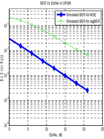
This difference in BER is further explained in Graphical user Interface of the OFDM as shown below in Fig 11.The GUI of OFDM is Plotted against BER and Eb/No.. Eb/No is the energy to the noise ratio
of the OFDM signal .The figure shows the Mean square error rate and the average error rate .It is clearly seen that the mean square error rate is always less than average bit error rate. The figure shows greatly reduction in BER as compared to conventional system which consist of single Antenna at transmitter and single antenna at Receiver. Compared to Conventional System, MIMO has greatly improve the performance of the system.
Fig 3. A Simple. diagram for MIMO System
[image:3.595.72.289.434.701.2]326 Fig 5. Parameter Of OFDM-MIMO
Fig6.Input Of OFDM-MIMO
Fig 7. Interleave Of OFDM-MIMO
[image:4.595.77.523.83.748.2]Fig8:Add Preamble
Fig 9. Channel Estimation Of OFDM-MIMO
327 Fig 11..Simple GUI OF OFDM
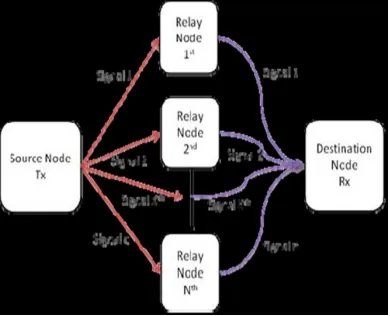
5. MIMO using Relay Selection
[image:5.595.77.287.387.635.2]Fig 13 .MIMO using relay selection
.
As the number of user in mobile communication ever increasing, it is the major concern of mobile network. To extend coverage area, data rate, quality of service etc. is a major problem of mobile network. Many project system discuss circumvent the need for exhaustive searching and increases the speed of convergence having low complexity and having high gain. Near-far problem is common in wireless
communication systems. MIMO system enable to increased spectral efficiency. This can be achieved using relays which is demonstrated below.
Source transmitter transmits multiple signals to increase efficiency then at relay node these signals are analysed using DF and AF protocol. From relay node transmit signal further to the receiver. Amplify and forward (AF) in which first amplify the received signal from the source node and forward it to the destination station. Decode and forward (DF) in which first decode the received signal from the source node and forward it to the destination station.AF happens to be first to the DF. RS improves the performance of conventional TDS as shown in fig 13 above.
6. System and Data Model
The source and destination nodes each have Nas
forward and Nad backward antennas, respectively, and
the relay nodes have Nar ,forward and backward
antennas with Nr intermediate nodes. Nas data streams
are transmitted in the system, and each is allocated to the correspondingly numbered antenna at the source node. The protocol operation of Decode and forward ,Amplify and forward is explained below.
6.1.Decode-and-Forward
The signal that is received at the first phase at the destination and nthrelay for i th symbol are given by following equation.
rsd[i] =Hsd[i]As[i]Ts[i]s[i] + ηsd[i] (1)
rsrn[i] =Hsrn[i]As[i]Ts[i]s[i] + ηsrn[i]. (2)
The structures Hsd[i]and Hsrn[i] are the Nad × Nad
source–destination and Nad × Nar source—nth relay
channel matrices, respectively. The quantities ηsd[i]
and ηsrn[i]. are the Nad × 1 and Nar × 1 vectors of zero mean
additive white Gaussian noise at the destination and nth relay, respectively, whose variances are σ2sd and σ2srn
and autocorrelation matrices σ2 sdINad and σ2srnINsrn..
The Nasx1 transmits the data at the transmitter side.At
the nth relay, the output of the reception and interference suppression procedure is denoted Zrn[i],
and the decoded symbol vector is given by
Srn[i] = Q(Zrn[i]) (3)
where Q(·) is a general quadrature-amplitude-modulation slicer.The Nad × 1 second-phase received
signal at the destination is the summation of the Nr relayed signals, yielding
Nr
r
rd[i] =
∑
H
rnd[i]A
rn[i]T
rn[i]
ˆ
s
rn[i] +
η
rd[i]
n=1
(4)0 5 10 15 20 25 10-5
10-4 10-3 10-2 10-1
Eb/No, dB
B
it
E
rr
o
r
R
a
te
BER Vs Eb/No in OFDM
Simulated BER for MSE Simulated BER for avgBER
RELAY
S
RELAYSDECODE DECODE
NORMALIZATION NORMALIZATION
AMPLIFY & FORWARD AMPLIFY
& FORWARD
RECEIVER DESTINATION NODE
328 where Hrnd is the nth relay–destination channel
matrix, and Arn[i] is the nth relay transmit power allocation matrix that proves the total transmit power of the second phase is unity The sum ation of(4)can be expressed in a more compact form given by
rrd[i] = Hrd[i]Ar[i]T r[i]ˆ.s[i] + ηrd[i] (5)
The final received signal at the destination is then formed by stacking the received signals from the relay and source nodes to give
r
d[i]
= ( 6)6.2. Amplify-and-Forward
rrd[i] = Hrd[i]Ar[i]T r[i].rsr[i] + ηrd (7)
where .rsr[i] = [rTsr1 [i] rTsr2 [i] . . . rTsrNr[i]]T can be interpreted as the AF equivalent of ˆ.s[i]. Expanding (7) yields
rrd[i] = Hrd[i]Ar[i]T r[i]Hsr[i]As[i]Ts[i]s[i]+
Hrd[i]Ar[i]T r[i].ηsr + ηrd (8)
8. Simulations
In this section, we presented the simulations of OFDM in terms of GUI of OFDM.This has shown improved performance of the system as compared to conventional system. In Fig.10, we consider the BER convergence performance of the proposed algorithms and compare them against systems with exhaustive TDS, no TDS and random TDS. The gains achieved by the proposed algorithms are also highlighted by their significantly better performance than the random TDS scheme
.
9. Conclusion
In this paper we have presented the OFDM system with MIMO system for improved performance of the system. We observed the spatial diversity and transmit diversity with relay selection algorithms for DF and AF, to further improve the data rates. We have proved that BER reduces down for MIMO system compared to conventional system. We compared conventional system with Present MIMO system
References
[1] D. H. Johnson and D. E. Dudgeon, 1993 “Array Signal
Processing:Conceptsand Techniques,” Englewood
Cliffs, NJ: Prentice-Hall.
[2] G. J. Foschini, 1996. “Layered space-time architecture for wireless communication in a fading environment when using multiple antennas,” Bell Labs.Tech. J., vol. 1, no. 2, pp. 41–59, Autumn .
[3] P. A. Zulch, J. S. Goldstein, J. R. Guerci, and I. S. Reed
Nov. 1998,“Comparison of reduced-rank signal
processing techniques,”in Proc. 32nd Asilomar Conf. Signals, Syst. Comput., PacificGrove, CA.
[4] L. Tong and S. Perreau, Oct. 1998 “Multichannel blind channel estimation: From subspace to maximum likelihood methods,”Proc. IEEE, vol. 86, pp.1951–1968. [5] .S. Thoen, L. Van der Perre, B. Gyselinckx, and M. Engels, Jan2001 “Performance analysis of combined transmit-SC/receive-RC,” IEEE Trans. Commun., vol. 49, no. 1, pp. 5 – 8,.
[6] M. L. Honig and J. S. Goldstein, Jun 2002 “Adaptive reduced-rank interference suppression based on the multistage Wiener filter,”IEEE Trans. Commun., vol. 50, no.6, pp. 986–994,..
[7] Berenguer, X. Wang, and V. Krishnamurhty, Nov. 2005 “Adaptive MIMO antenna selection via discrete stochastic optimization,” IEEE Trans. Signal Process., vol. 53, no. 11, pp. 4315–4329,
[8] Fan and J. Thompson, May 2007. “MIMO
configurations for relay channels: Theory and practice,” IEEE Trans. wirelessCommun., vol. 6, no. 5, pp. 1774– 1786.
[9] R. C. de Lamare, R. Sampaio-Neto, and A. Hjrungnes, Dec. 2007 “Jointiterative interference cancellation and parameter estimationfor CDMA systems,” IEEE Commun. Lett., vol. 11, no. 12, pp. 916–918.
[10] S.W. Peters and R. Heath, 2008 “Non
regenerative MIMO relaying with optimal transmit antenna selection,” IEEE Signal Process. Lett., vol. 15, pp. 421–424.
[11] H. Zhang, H. Dai, and B. L. Hughes, Jan. 2009. “Analysis on the diversitymultiplexing tradeoff for ordered MIMO SIC receivers,” IEEE Trans.Commun., vol. 57, no. 1, pp. 125–133,
[12] R. Fa and R. C. de Lamare, May 2011 “Multi-branch successive interference cancellation for MIMO spatial multiplexing systems: Design, analysis and adaptive implementation,” IET Commun., vol. 5, no. 4, pp. 484–494.
[13] Batu Chalise, Yimin Zhang, and Moeness Amin, ,