LARGE SYSTEMS
ASSEMBLY
INSTRUCTIONS
'C
DPS8000
SUBJECT
GCOS8
ASSEMBLY
INSTRUCTIONS
DPS8000
Description of the Assembly Instructions for the DPS 8000 Information System.
SOFTWARE SUPPORTED
GCOS 8 Software Release 2500
DATE
March 1987
ORDER NUMBER
DZ51-00
Worldwide
Infonnation
Systems
PREFACE
This manual contains information that enables the user to code programs in symbolic machine language which is then translated into binary machine instructions.
This manual is directed to users who are experienced in coding within the
environment of a large-scale computer installation. Considerable knowledge and practical experience is required in the use of address modification with
indirection, hardware indicators, fault interrupts and recovery routines, macro operations, pseudo-operations, and other features normally encountered in a large computer with a flexible instruction repertoire under control of a master executive program. It is assumed that the user is familiar with the two's complement number system.
This manual includes the processor capabilities, modes of operation, detailed descriptions of machine instructions, virtual memory addressing, paging, and the representation of data. It should prove useful to programmers who are responsible for analyzing conditions that cause system failures.
In this document, multiple vertical braces and brackets should be assumed to be a single brace or bracket; for example:
{ }
{ }
{ }
represents{
}
[ ]
and [ ]
[ ] represents [ ]
BULL DISCLAIMS THE IMPLIED WARRANTIES OF MERCHANTABILlTY AND FITNESS FOR A PARTICULAR PURPOSE AND MAKES NO EXPRESS WARRANTIES EXCEPI' AS MAY BE STATED IN ITS WRITTEN AGREEMENT WITH AND FOR ITS CUSTOMER. IN NO EVENT IS BULL LIABLE TO ANYONE FOR ANY INDIRECT, SPECIAL, OR CONSEQUENTIAL DAMAGES.
LISTING AND CORRECTING
DOCUMENTS
The Problem Analysis Solution System (PASS) data base is an online tool that provides direct communications between Bull software development organizations and Bull customers. Documentation-related transactions available to customers via PASS include those which:
• Generate a list of all software documents published for the current Software Release.
• Prepare Software Technical Action Requests (STARs) regarding documentation discrepancies.
Logon procedures for these functions and procedures for using PASS can be obtained by contacting the Bull Technical Assistance Center (TAC).
DOCUMENT LISTING
A list of all GeOS 8 System software documents published for this Software Release and available through the Bull CSO Marketing and Sales Order Entry (telephone 1-800-343-6665) can be
displayed via the NEWS facility of PASS. The document lists are available via the PASS meeting SWDOC_AV AILABILITY.
DOCUMENTATION CORRECTIONS
Customers can submit documentation error reports via the PASS online STAR Maker facility. Responses to STARs, as well as other documentation changes, also are contained on PASS. (Documentation corrections contained on PASS may apply to prior Software Releases as well as to the current Software Release.)
In addition, corrections to documents will be entered on the PASS data base. Query PASS
periodically to determine if any corrections exist. Corrections documented on PASS, if applicable to the next release of the software, will be incorporated in to the next update of the manual.
(
(
(
CDNTBN'l'S
SECTION 1 INTRODUCTION ••••••••••••••••••••••••••••••••••••••••••••••
Processor Features ••••••••••••••••••••••••••••••••••••••••••••••••••• Pipeline Architecture Of The DPS 8000 •••••••••••••••••••••••••••••• Faults And Interrupts •••••••••••••••••••••••••••••••••••••••••••••• Connect/Interrupt Mechanism •••••••••••••••••••••••••••••••••••••••• Online Processor Tests ••••••••••••••••••••••••••••••••••••••••••••• Operator Modes •••••••••••••••••••••••••••••••••••
Processor Modes Of Operation ••••••••••••••••••• Non-Extended/Extended Modes •••••••••••••••••••• Memory Addressing Modes •••••••••••••••••••••••• Virtual Memory Paging •••••••••••••••••••••••• Absolute Mode ••••••••••••••••••••••••••••••••
· ... .
·
... .
· ... .
· ... .
· ... .
Reserved Memory Space •••••••••••••••••••••••••••••••••••••••••••••••• Interval Timer •••••••••••••••••••••••••••••••••••••••••••••••••••••••
SECTION 2 REPRESENTATION OF DATA •••••••••••••••• • • • • • • • • • • • • • • • i • • • •
Formats ••••••••••••••••••••••••••••••••••••••••••••••••••••••••••••••
position Numbering ••••••••••••••••••••••••••••••••••••••••••••••••••• The Machine Word ••••••••••••••••••••••••••••••••••••••••••••••••••••• Character-Strings •••••••••••••••••••••••••••••••••••••••••••••••••••• Character Positions •••••••••••••••••••••••••••••••••••••••••••••••• Bit Positions ••••••••••••••••••••••••••••••••••••••••••••••••••••••
Li terals .••..•••..•..•••••••.••.••..••...•.••••••••••••••••.•••••••••
Binary Numbers •••••••••••••••••••••••••••••••••••••••••••••••••••••••
Fixed-Point Numbers •••••••••••••••••••••••••••••••••••••••••••••••• Floating-Point Numbers ••••••••••••••••••••••••••••••••••••••••••••• Hexadecimal Floating-Point Numbers ••••••••••••••••••••••••••••••••• Quadruple-Precision Numbers •••••••••••••••••••••••••••••••••••••••• Normalized Binary Floating-Point Numbers ••••••••••••••••••••••••••• Binary Representation Of Fractional Values •••••••••••••••••••••••••
Decimal Numbers ••••••••••••••••••••••••••••••••••••••••••••••••••••••
Decimal Data Character Codes ••••••••••••••••••••••••••••••••••••••• Floating-Point Decimal Numbers ••••••••••••••••••••••••••••••••••••• Decimal Number Ranges ••••••••••••••••••••••••••••••••••••••••••••••
SECTION 3 MEMORY ORGANIZATION •••••••••••••••••••••••••••••••••••••••
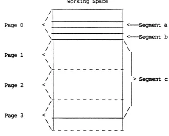
Virtual Memory ••••••••••••••••••••••••••••••••••••••••••••••••••••••• Working Spaces ••••••••••••••••••••••••••••••••••••••••••••••••••••• Page. Tables •••••••••••••••••••••••••••••••••••••••••••••••••••••••• :Domalns ••••••••••••••••••••••••••••••••••••••••••••••••••••••••••••
Segments •••••••••••••••••••••••••••••••••••••••••••••••••••••••••••
Deser i ptors •••••••••••• ' ••••••••••••••••••••••••••••••••••••••••••••
OOICi15lr.l"S (cent)
Standard Descriptor •••••••••••••••••••••••••••••••••••••••••••••• Standard Descriptor With Working Space Number •••••••••••••••••••• Supe:r Deser i ptor •••••••••••••.••••••••••••••••••••••••••••••••• ~ ... Supe:r Descriptor With Working Space Number ••••••••••••••••••••••• Extended Descriptor •••••••••••••••••••••••••••••••••••••••••••••• Extended De~criptor With Working Space Number •••••••••••••••••••• Entry Descrlptor •••••••••••••••••••••••••••••••••••••••••••••••••
o °nk° De 0
DyDamlC Ll lng scrlptor ••••••••••••••••••••••••••••••••••••••• Shrinking ••••••••••••••••••••••••••••••••••••••••••••••••••••••••
SECTION 4 PROCESSOR ACCESSIBLE R~STERS •••••••••••••••••••••••••••• Accumulator Register (A) •••••••••••••••••••••••••••••••••••••••••••••
Quotient Register (Q) ••••••••••••••••••••••••••••••••••••••••••••••••
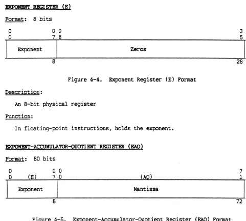
Accumulator-Quotient Register (AQ) ••••••••••••••••••••••••••••••••••• EXponent Register (E) ••••••••••••••••••••••••••••••••••••••••••••••••
Exponent-Accumulator-Quotient Register (EAQ) •••••••••••••••••••••••••
I..ow Operand Register (LOR) •••••••••••••••••••••••••••••••••••••••••••
Index Registers (xn) •••••••••••••••••••••••••••••••••••••••••••••••••
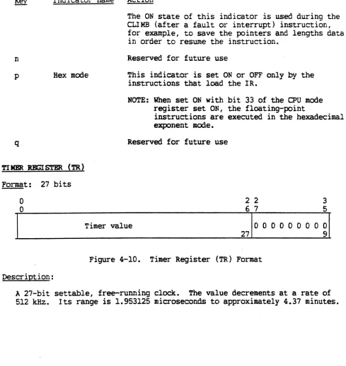
General Index Registers (GXn) •••••••••••••••••••••••••••••••••••••••• Indicator Register (IR) •••••••••••••••••••••••••••••••••••••••••••••• Timer Register (TR) •••••••••••••••••••••••••••••••••••••••••••••••••• Instruction Counter (Ie) ••••••••••••••••••••••••••••••••••••••••••••• Address Registers (ARn) •••••••••••••••••••••••••••••••••••••••••••••• Linkage Segment Register (LSR) •••••••••••••••••••••••••••••••••••••••
Instruction Segment Register (ISR) ••••••••••••••••••••••••••••••••••• Segment Descriptor Registers (DRn) ••••••••••••••••••••••••••••••••••• Segment Identity Registers (SEG[Dn) •••••••••••••••••••••••••••••••••• Instruction Segment Identity Register - S~D(IS) •••••••••••••••••••• Pointer Registers (PR) •••••••••••••••••••••••••••••••••••••••••••••••
Option Register (OR) •••••••••••••••••••••••••••••••••••••••••••••••••
calendar Clock Register (eCR) •••••••••••••••••••••••••••••••••••••••• Working Space Registers (WSRn) ••••••••••••••••••••••••••••••••••••••• safe Store Register (SSR) •••••••••••••••••••••••••••••••••••••••••••• Stack Control Register (SCR) •••••••••••••••••••••••••••••••••••••••••
Argument Stack Register {ASR) •••••••••••••••••••••••••••••••••••••••• Parameter Segment Register (PSR) •••••••••••••••••••••••••••••••••••••
High Water Mark Register (HWMR) •••••••••••••••••••••••••••••••••••••• Data Stack Descriptor Register (DSDR) •••••••••••••••••••••••••••••••• Data Stack Address Register (DSAR) ••••••••••••••••••••••••••••••••••• Page Directory Base Register (PDBR) ••••••••••••••••••••••••••••••••••
O>U Moo.e Register (MR.) •••••.•••••••••••••••••••••••••••••••••••••••••• cache Mode Register (CMR), Lockup Fault Register (LUF} ••••••••••••••• Configuration Register (PORT ASSIGNMENT) (CR) ••••••••••••••••••••••••
", ,
Page 3-8 3-10 3-11 3-12 3-12 3-13 3-14 3-15 3-16 4-1 4-3 4-4 4-4 4-5 4-5 4-6 4-6 4-7 4-8 4-12 4-13 4-13
4-15 "- _/J
(
CDlft'BIITS (cxm.t)
CPU Number Reg-ister (NR) ..•••.••••••.••••••••.••••••.•.•••.•••...•••.
Interrupt Mask Register (IMR) ••••••••••••••••••••••••••••••••••••••••
CPU Fault Reg-ister (FR) •.•••••••••••••••••••••••••.•••••••••••••••••. Extended Fault Register (EFR) ••••••••••.•..••.••••••.•••••.•••••.•••. History Register (RR) ••..••••••••••••••.••••.•••••••••••••••••••••••.
Reserve Memory Base Register (RMBR) •••••••••••••••••••••••••••••••••• SCU Fault Register (SCUFR) ••••••••••••••••••••••••••••••••••••••••••.
Syndrome Register (SYR) •••.••••••••••••••••••••.••••••••••••••••••••.
SCU Configuration Register (SCUCR) ••••••••••••••••••••••••••••••••••• SCU History Register <SCURR) •.•••••••••••••••••••••••.••••••.•••••••. Memory Error Status Register (MSR) ••••••••••••••••••••••••••••••••••• Memory Identification Register (MID) •••••••••••••••••••••••••••••••••
SECTION 5 ADDRESS MODIFICATION AND DEVELOPMENT ••••••••••••••••••••••
Address Modification Features •••••••••••••••••••••••••••••••••••••••• Address Generation In The NS Mode ••••••••••••••••••••••••••••••••••••
Basic Modification .••••.•.••••.•••••.••••••.•.••.••••••••••••••••.• Indirect Addressing ...•.•...••••.•.••••••.••.••••••.••••.•••••••... Tag Field ... · ... . Types Of Address Modification .••.•••••.••.•••..••••.••••.••.•.•.••.
Register (R ) ••••.•.•.••.•.••••••••••••••••.•••••••••••••••••.•.••
Register Then Indirect (RI} •••••••••••••••••••••••••••••••••••••• Indirect Then Register (IR} •••••••••••••••••••••••••••••••••••••• Indirect Then Tally (IT) •••••••••••••••••••••••••••••••••••••••••
Indirect Word Format ..•.•.•.•.•••••••..•.•••.••.•••••••••.•..•.
variations Under IT Modification ••••••••••••••••••••••••••••••• Address Modification Octal Codes ••••••••••••••••••••••••••••••••••• Address Modification Flowchart •••••••••••••••••••••••••••••••••••••
Floa.table Code ...•...•. .,.· ••...•..••..•••••••••.•••••••••.
Address Modification With Address Registers •••••••••••••••••••••••• Single-Word Address Modification ••••••••••••••••••••••••••••••••• Multiword Address Modification ••••••••••••••••••••••••••••••••••• Multiword Modification Field •••••••••••••••••••••••••••••••••••••
Operand Deser i ptors ...•...••.•••.••.••••.••.•...
Bit String Operand Descriptor •••••••••••••••••••••••••••••••••••• Alphanumeric Operand Descriptors ••••••••••••••••••••••••••••••••• Numeric Operand Descriptors ••••••••••••••••••••••••••••••••••••••
Indirect Word .•..•••••.•••.•••.•••••••.•••••••••••••••.••••.•••.•
Operand Descriptor Address Preparation ••••••••••••••••••••••••••• Bit String Address Preparation ••••••••••••••••••••••••••••••••• Alphanumeric/Numeric Address Preparation ••••••••••••••••••••••• Address Generation In The ES Mode •••••••••••••••••••••••••••••••••••• Instruction Address Field And Register Formats ••••••••••••••••••••• Instruction Address Field •••••••••••••••••••••••••••••••••••••••• Address Modification With No AR Indicated •••••••••••••••••••••• Address Modification With AR Indicated •••••••••••••••••••••••••
Tag Field Modification ....•....•...•...•.•.•••.••...•.•..
Operand Descriptor Modification •••••••••••••••••••••••••••••••• Address Development •••••••••••••••••••••••••••••••••••••••••••••••••• Virtual Hemory Addressing ••••••••••••••••••••••••••••••••••••••••••
OJ)erand Ad.d.ress Proced.ure •••••••••••••••••••••••••••••••••••••••• Instruction Address Procedure •••••••••••••••••••••••••••••••••••• Virtual Address Generation For NS Mode ••••••••••••••••••••••••••••• Standard Descriptor NS Mode •••••••••••••••••••••••••••••••••••••• Super Descriptor NS Mode ••••••••••••••••••••••••••••••••••••••••• Extended Segment Descriptor NS Mode •••••••••••••••••••••••••••••• Virtual Address Generation For ES Mode ••••••••••••••
...
Standard Descriptor ES Mode •••••••••••••••••••••••••••••••••••••• Extended Segment Descriptor ES Mode •••••••••••••••••••••••••••••• Abs~lute Addressing Hode ••••••••••••••••••••••••••••••••••••••••••• Paglng ••••••••••••••••••••••••••••••••••••••••••••••••••••••••••••• Address Translation Process •••••••••••••••••••••••••••••••••••••• Page Table Directory Word Format ••••••••••••••••••••••••••••••••• Page Table Base Word Format •••••••••••••••••••••••••••••••••••••• Page Table Word Format ••••••••••••••••••••••••••••••••••••••••••• Mapping The Virtual Address To A Real Address •••••••••••••••••••• Dense Page Table ••••••••••••••••••••••••••••••••••••••••••••••••• Locating The Page Table Directory Word ••••••••••••••••••••••••••• section Table •••••••••••••••••••••••••••••••••••••••••••••••••••• Associative Memory ••••••••••••••••••••••••••••••••• · •••••••••••••• cache Memory ••••••••••••••••••••••••••••••••••••••••••••••••••••• Address Truncation ••••••••••••••••••••••••••••••••••••••••••••••••• Bounds Checking •••••••••••••••••••••••••••••••••••••••••••••••••••• Word And Double-Word Operations •••••••••••••••••••••••••••••••••• Byte Operations •••••••••••••••••••••••••••••••••••••••••••••••••• Bit Strings And Table Of Translate Instruction ••••••••••••••••••• Bound Check Eq'uations ... .
SECTION 6 FAULTS AND INTERRUP'l'S •
...•...
Description Of Faults And Interrupts ••••••••••••••••••••••••••••••••• Fault Procedures ••••••••••••••••••••••••••••••••••••••••••••••••••••• Fault
Fault
Priority •••••••••••••••••••
Recognition ••••••••••••••••
...
...
Fault categories ••••••••••••••••••••••••• e· • • • • • • • • • • • • • • • • • • • • • • • • • • •Instruction-Generated Faults ••••••••••••••••••••••••••••••••••••••• Program-Generated Faults ••••••••••••••••••••••••••••••••••••••••••• Virtual Memory-Generated Faults •••••••••••••••••••••••••••••••••••• Hardware-Generated Faults ••••••••••••••••••••••••••••••••••••••••••
Mocle Faul ts ••••••••••••••••••••••••••••••••••••••••• e • • • • • • • • • • • • • • • •
(
CDHTBIftS (c:ont)
Page Table Word Control Field Faults •••••••••••••
I nterrupt Procedures ••••••••••••••••••••••••••••••••••••••••••••••••• System Controller Interrupts •••••••••••••••••••••••••••••••••••••••
1 nward CLI MB Interrupts •••••••••••• ,.. ••••••••••••••••••••••••••••••
Multiword Instruction Interrupts ••••••••••••••••••••••••••••••••••• IC Values Stored On Faults And Interrupts ••••••••••••••••••••••••••••
SECTION 7 MACHINE INSTRUCTION FUNCTIONS ••••••••••••••••••••••••••••.
Single-Word Instructions ••••••••••••••••••••••••••••••••••••••••••••• Address Register Instructions •••••••••••••••••••••••••••••••••••••• Boolea.n Operations ••••••••••••••••••••••••••••••••••••••••••••••••• ComJ)a.r ison Operations •••••••••••••••••• "... ••••••••••••••••• Data Movement Instructions ••••••••••••••••••••••••••••••••••••••••• Data Shifting Instructions ••••••••••••••••••••••••••••••••••••••••• Effective Address To Register Instructions ••••••••••••••••••••••••• Fixed-Point Arithmetic Instructions •••••••••••••••••••••••••••••••• Floating-Point Arithmetic Instructions ••••••••••••••••••••••••••••• Quadruple-Precision Floating-Point Instructions •••••••••••••••••••• Privileged Master Mode Instructions •••••••••••••••••••••••••••••••• Miscellaneous Instructions ••••••••••••••••••••••••••••••••••••••••• Special Processor Instructions ••••••••••••••••••••••••••••••••••••• Multiword Instructions ••••••••••••••••••••••••••••••••••••••••••••••• Alphanumeric Instructions •••••••••••••••••••••••••••••••••••••••••• Numeric Instructions ••••••••••••••••••••••••••••••••••••••••••••••• Bit String Instructions •••••••••••••••••••••••••••••••••••••••••••• Conversion Instructions ••••••••••••••••••••••••••••••••••••••••••••
Edi ted. Move 1 nstruct ions •••••••••••••••••••••••••••••••••••••••••••
Multiword Instruction capabilities ••••••••••••••••••••••••••••••••• Address Register Instructions ••••••••••••••••••••••••••••••••••••••••
Address Register I.,oa.d •••••••••••••••••••••••••••••••••••••••••••••• Address Register Store ••••••••••••••••••••••••••••••••••••••••••••• Alter Address Register Contents •••••••••••.•••••••••••••••••••••••• special Address Register Instructions •••••••••••••••••••••••••••••• Boolean Operation Instructions ••••••••••••••••••••••••••••••••••••••• Boolean Expressions... • ••••••••••••••••• Evaluation Of Boolean Expressions ••••••••••••••••••••••••••••••••••
Boolean AND •••••••••••••••••••••••••••••••••••••••••••••••••••••••• Boolean OR ••••••••••••••••••••••••••••••••••
Bool ean EXCLUSI VB OR... ••••••••••••••••
Boolean COMPAR.ATI VE AND •••••••••••••••••••••••••••••••••••••••••••• Boolean COMPAR.ATIVE NOT AND •••••••••••• : •••••••••••••••••••••••••••
Fixed-Point Instructions ••••••••••••••••••••••••••••••••••••••••••••• Data Movement I.,oa.d •••••••••••••••••••••••••••••••••••••••••• o • • • • • • •
Data Movement Store •••••••••••••••••••••••••••••••••••••••••••••••• Data Movement Shift •••••••••••••••••••••••••••••••••••••••••••••••• Fixed-Point Addition ••••••••••••••••••••••••
Fixed-Point Subtraction ••••••••••••••••••••••••••••••••••••••••••••
CDlITBlI'l"S (amt)
F~xed-Po~nt M~l~i~lication .••...••...••••.•..•••••••• ~ •.•••.••••••• Flxed-Polnt Dlvlslon ••••••••••••••••••••••••••••••••••••••••••••••• Fixed-Point Comparison ••••••••••••••••••••••••••••••••••••••••••••• Fixed-Point Negate •••••••••••••••••••••••••••••• , •••••••••••••••••• Floating-Point InstructioilS •••••••••••••••••••••••••••••••••••••••••• Data Movement Load ••••••••••••••••••••••••••••••••••••••••••••••••• Data Movement Store •••••••••••••••••••••••••••••••••••••••••••••••• Floating-Point Addition •••••••••••••••••••••••••••••••••••••••••••• Floating-Point Subtraction ••••••••••••••••••••••••••••••••••••••••• Floating-Point Multiplication •••••••••••••••••••••••••••••••••••••• Floating-Point Division •••••••••••••••••••••••••••••••••••••••••••• Floating-Point Comparison •••••••••••••••••••••••••••••••••••••••••• Floating-Point Negate •••••••••••••••••••••••••••••••••••••••••••••• Floating-Point Normalize ••••••••••••••••••••••••••••••••••••••••••• Floating-Point Round ••••••••••••••••••••••••••••••••••••••••••••••• Floating-Point Truncate Fraction ••••••••••••••••••••••••••••••••••• Quadruple-Precision Instructions ••••••••••••••••••••••••••••••••••••• Nul ti word Instructions •••••••••••••••••••••••••••••••• · ••••••••••••••• Multiword Instruction Format ••••••••••••••••••••••••••••••••••••••• Multiword Modification Field ••••••••••••••••••••••••••••••••••••• Operand Descriptors And Indirect Words ••••••••••••••••••••••••••••• Operand Descriptor Indirect Word Format •••••••••••••••••••••••••• Alphanumeric Instructions •••••••••••••••••••••••••••••••••••••••••• Alphanumeric Operand Descriptor Format ••••••••••••••••••••••••••• Alphanumeric Compare ••••••••••••••••••••••••••••••••••••••••••••• Alphanumeric Move •••••••••••••••••••••••••••••••••••••••••••••••• Character Move To/From Register Instructions ••••••••••••••••••••••• Operand Descriptor For Character Move Instructions ••••••••••••••• Character Move Instruction Repertoire •••••••••••••••••••••••••••• Numeric Instructions ••••••••••••••••••••••••••••••••• · •••••••••••••• Numeric Operand Descriptor Format •••••••••••••••••••••••••••••••• Numeric Compare ••••••••••••••••••••••••••••••••••••••••••••••••••
Numer i c Move •••••••••••••••••••••••••••••••••••••••••••••••••••••
Bit String Instructions •••••••••••••••••••••••••••••••••••••••••••• Bit String Operand Descriptor Format •••••••••••••••••••••••••••••
B~t Str~ng Combine ••••••••••••••••••••••••••••••••••••••••••••••• BIt Strlng Compare ••••••••••••••••••••••••••••••••••••••••••••••• Bit String Set Indicators •••••••••••••••••••••••••••••••••••••••• Data Conversion Instructions ••••••••••••••••••••••••••••••••••••••• Arithmetic Instructions ••••••••••••••• ' ••••••••••••••••••••••••
Decimal Decimal Decimal Decimal
Add it ion ••••••••••••••••••••.••••••••••••••••••••••• Subtraction •••••••••••••••••••••••••••••••••••••••••
1 '1' ,
M~ ~l~ lcatlon ••••••••••••••••••••••••••••••••••.•••
Dl V1Slon ••••••••••••••••••••••••••••••••••••••••••••
.
.
.
. .
, /
Page '--- .7
(
CDRTBHTS (amt)
Numer i c F.cl i t (MVNE AND MVNEX} •••••••••••••••••••••••••••••••••••• Alphanumeric F.cli t (MVE) ••••••••••••••••••••••••••••••••••••••••••
Micro Operation Repertoire •••.••••.•.••.••••••••••••••••.••••••••••
Micro Operations Descriptions ••••••••••••••••••••••••••••••••••••••
Ecii t Flags ...•...•....•...•...
Micro Operation Code Assignment Map •••••••••••••••••••••••••••••••• Terminating Micro Operations •••••••••••••••••••••••••••••••••••••••
Virtual Memory Instructions ...•....•••..••••••••.•.•.•••...•....••••.
Descriptor Register Instructions ••••••••••••••••••••••••••••••••••• Pointer Register Instructions ••••••••••••••••••••••••••••••••••••••
Domain Transfer (ClJMB) •••••••••••••.•••••••••••••••••••••.•••••••• Privileged Instructions .••..••••.•.•.•.••.•••••••••••.••••.••.••.••••
Clear Associative Memory Pages •••••••••••••••••••••••••••••••••••
Clear Ce.che ••••••••••••••••••••••••••••••••••••• ~ ••••••••••••••••
Register I.oa.d ..•••••.•••••••••••.•••••••••••••••••••••••••••••••• Register Store •••••••••••••••.••••••••••••••••••••••••••••.•••.••
Memory Control ..••...•...••.•..••..••.•••••••••••••••...•.••••
System Control ••••••••••••••••••.•••••••••••••••••••••••••••••••• All Mcxle I nstruct ions •••.•••••••••••••.•••••••••••••••••.••••••••••••
ES Mc::x:ie I nstruct ions ••••••••••••••••••••••••••••.• ••••••••••••••••••••
Register-to-Register Instructions •••••••••••••••••••••••••••••••••• RR Type Instruction Format ••••••••••••••••••••••••••••••••••••••• Movement And Arithmetic Instructions •••••••••••••••••••••••••••••
Shift Instructions ... . Fixed-Point Instructions ...•...••...••••..••.••••....•••.••..•
Transfer Instructions ••••••••••••••••••••• Conditional Transfer •••••••••••••••••••• Unconditional Transfer •••••••••••••••••• Miscellaneous Instructions ••••••••••••••••
·
... .
·
... .
Option Register Instructions ••••••.••••••••••••••••••••••••••••••••Binary-To-BCD Conversion ..•.•...•...•..•••.•••••••••••••..•••.••
Execute Instructions ••.•••.••••.••••.•••••••••••••••••••••••••••.••
Gray-To-Binary-Conversion •..•...••..•••••.•••••••••.••.•••..••
Programmed Faul t. . . ... .
No Operation ...•...•..•....••.. e • e . • • • • • • • • • • • • • • • • •
Repeat Instructions ... .
Pointer And Length Instructions •••••••••••••••••••••••••••••••••••• Coding Limitations ...••...•...•....••.••••..•••••••...•.••••..••
SECTION 8 MACHINE INSTRUCTION DESCRIPTIONS •••••••••••••••
. . .
. .
.
.
. .
Format Of Instruction Description ••••••••••••••••••••••••••••••••••••
Abbreviations And Symbols ••••••••••••••••••••••••••••••••••••••••••••
Common Attributes Of Instructions •••••••••••••••••••••••••••••••••••• Illegal Modification ••••••••••••••••••••
Parity Indicator ... .
Instruction Word Formats •••••••••••••••••• Single-Word Instructions ••••••••••••••••
CDliTBH'.L'S (cant)
Multiword Instructions .•.•.•••••••••••••••••.•••.•••••••••.•••..•••
Address Register Special Arithmetic Instructions ••••••••••••••••••• Character Move To/From Register Instructions ••••••••••••••••••••••• Register-te-Register Instructions •••••••••••••••••••••••••••••••••• Instruction Repertoire .•••••••••••••••••••••••.•••.••••••••••••••.•••
APPENDIX A OPERATION CODE MAPS ••••••••••••••••••••••••••••••••••••••
APPENDIX B OBSOLETE INSTRUCTION CODES •••••••••••••••••••••••••••••••
APPENDIX C CHARACTER SETS •••••••••••••••••••••••••••••••••••••••••••
Unified Character Set ASClI SEQUENCE ••••••••••••••••••••••••••••• Unified Character Set EBCDIC Sequence •••••••••••••••••••••••••••• Unified Character Set GBCD Sequence •••••••••••••••••••••••••••••• Unified Character Set HBCD Sequence ••••••••••••••••••••••••••••••
I HDEX ••••••••••••••••••••••••••••••••••••••••••••••••••••••••••••••••
I LLDS'l'RA"l'I OKS
Figure 3-1 3-2 3-3 4-1 4-2 4-3 4-4 4-5 4-6 4-7 4-8 4-9 4-10 4-11 4-12 4-13 4-14 4-15
Domain Of Noncontiguous Segments ••••••••••••••••••••••••••••••• Layout Of Segments On Pages •••••••••••••••••••••••••••••••••••• Shrunken Descriptor For Corresponding New Segment •••••••••••••• Accumulator Register (A) Format •••••••••••••••••••••••••••••••• Quotient Register <Q} Format •••••••••••••••••••••••••••••••••••
Accumulator-Quotient Register (AQ) Format •••••••••••••••••••••• Exponent Register (E) Format ••••••••••••••••••••••••••••••••••• Exponent-Accumulator-Quotient Register (EAQ) Format •••••••••••• Low Operand Register Format •••••••••••••••••••••••••••••••••••• Index Register (Xn) Format ••••••••••••••••••••••••••••••••••••• General Index Registers (GXn) Format ••••••••••••••••••••••••••• Indicator Register (IR) Format ••••••••••••••••••••••••••••••••• Timer Register (TR) Format ••••••••••••••••••••••••••••••••••••• Instruction Counter (IC) Format •••••••••••••••••••••••••••••••• Address Register (ARn) Format (NS Mode) •••••••••••••••••••••••• Address Register (ARn) Format (ES Mode) •••••••••••••••••••••••• Linkage Segment Register (LSR) Format •••••••••••••••••••••••••• Instruction Segment Register (ISR) Format ••••••••••••••••••••••
Page 8-9 8-10 8-11 8-12 8-14 A-1 B-1 C-1 C-1 C-4 C-10 C-12 i-1 Page 3-3 3-5 3-16 4-3 4-4 4-4 4-5 4-5 4-6 4-6 4-7 4-8 4-12 4-13 4-13 4-14 4-15 4-15 , /
"
(
ILLUSTRATIOIfS (cont)
Figure 4-20 4-21 4-22 4-23 4-24 4-25 4-26 4-27 4-28 4-29 4-30 4-31 4-32 4-33 4-34 4-35 4-36 4-37 4-38 4-39 4-40 4-41 4-42 4-43 4-44 5-1 5-2 5-3 5-4 5-5 5-6 5-7 5-8 5-9 5-10 5-11 5-12 5-13 5-14 5-15 5-16 5-17 5-18 5-19 5-20 5-21 5-22
Working Space Register (WSRn) Format ••••••••••••••••••••••••••• safe Store Register (SSR) Format ••••• ~ ••••••••••••••••••••••••• Argument Stack Register (ASR) Format •••••••••••••••••••••••••••
Parameter Segment Register (PSR) Format •••••••••••••••••••••••• High Water Mark Register (HWMR) Format ••••••••••••••••••••••••• Data Stack Descriptor Register (DSDR) Format ••••••••••••••••••• Data Stack Address Register (DSAR) Format •••••••••••••••••••••• Page Directory Base Register (PDBR) Format ••••••••••••••••••••• CPU Mode Register (MR) Format •••••••••••••••••••••••••••••••••• cache Mode Register (CMR), Lockup Fault Register Format (LUF) •• Configuration Register (Port Assignment) (CR) ••••••••••••••••• Address Trap Register (ATR) Format ••••••••••••••••••••••••••••• Virtual Address Trap Register (VATR) Format •••••••••••••••••••• CPU Number Register (NR) Format •••••••••••••••••••••••••••••••• Interrupt Mask Register (IMR) Format ••••••••••••••••••••••••••• Fault Register (FR) Format •••••••••••••••••••••••••••••••••••••
Extended Fault Register (EFR) Format •••••••••••••••••••••••••••
History Register (HR) Format ••••••••••••••••••••••••••••••••••• Reserve Memory Base Register (RMBR) Format ••••••••••••••••••••• System Control Unit Fault Register (SCUFR) Format •••••••••••••• Syndrome Register (SYR) Format ••••••••••••••••••••••••••••••••• SCU Configuration Register (SCUCR) Format •••••••••••••••••••••• SCU History Register (SCUHR) Format •••••••••••••••••••••••••••• Memory Error Status Register Format •••••••••••••••••••••••••••• Memory Identification Register (MID) ••••••••••••••••••••••••••• Indirect Word Format ••••••••••••••••••••••••••••••••••••••••••• Address Modification Flowchart ••••••••••••••••••••••••••••••••• Single-Word Instruction Format ••••••••••••••••••••••••••••••••• Address Preparation For Single-Word Instruction •••••••••••••••• Multiword Instruction Format •• · ••••••••••••••••••••••••••••••••• Bit String Operand Descriptor Format ••••••••••••••••••••••••••• Alphanumeric Operand Descriptor Format ••••••••••••••••••••••••• Numeric Operand Descriptor Format •••••••••••••••••••••••••••••• Indirect Word Format ••••••••••••••••••••••••••••••••••••••••••• Flowchart For Operand Descriptor Address Preparation ••••••••••• Virtual Address Generation Using Standard Descriptor (NS Mode). Virtual Address Generation Using Super Descriptor (NS Mode) •••• Virtual Address Generation Using Extended Segment Des·criptor
(NS Mode) ••••••••••••••••••••••••••••••••••••••••••••••••••••••
Virtual Address Generation Using Standard Descriptor (ES Mode). Virtual Address Generation Using Extended Segment Descriptor
(ES ~ode) ••••••••••••••••••••••••••••••••••••••••••••••••••••••
Effective Absolute Address ••••••••••••••••••••••••••••••••••••• Page Table Directory Word (PTDW) Format •••••••••••••••••••••••• Page Table Base Word (PBW) Format •••••••••••••••••••••••••••••• Page Table Word (PTW) Format ••••••••••••••••••••••••••••••••••• Virtual Address •••••••••••••••••••••••••••••••••••••••••••••••• Address Mapping Using A Dense Page Table •••••••••••••••••••••••
PTDW Address ••••••••••••••••••••••••••••••••••••••••••••••.••••
I LLUS'l'RATI OBS (cant) Figure 5-23 5-24 5-25 5-26 5-27 5-28 5-29 5-30 5-31 5-32 7-1 7-2 7-3 7-4 7-5 7-6 7-7 7-8 7-9 7-10 8-1 8-2 8-3 8-4 8-5 8-6 8-7 8-8 Table 1-1 2-1 2-2 4.-1 4-2 4-3 5-1
P'I'W Address •••••••.••••.••••••••••••.•••••••••••••••••••••••••. Word Address ..•••••••.••••••••••••••.••••.••••••••••••••••••••.
Virtual Address ••••••••••••••••••••••••••••••••••••••••••••••••
Address Napping Using A Section Table •••••••••••••••••••••••••• PBW Address ••••••••••••••••••••••••••••••••••••••••.••••••••••• P'I'W Address •••••••••••••••••••••••••••••••••••••••••••••••••••. Word Address ••••••••••••••••••••••••••••••••••••••. e • • • • • • • • • • • •
Page Table Word Associative Memory (PTWAM) Format •••••••••••••• Associative Memory Directory Word ••••••••••••••••••••••••••••••
cache Directory Word ...•••••••••••••.••.•••••••••••••••••••••••
Single-word Instruction With Address Modification •••••••••••••• Alter Address Register COntents •••••••••••••••••••••••••••••••• Special Address Register Instructions •••••••••••••••••••••••••• Multiword Instruction Format ••••••••••••••••••••••••••••••••••• Operand Descriptor Indirect Word Format •••••••••••••••••••••••• Alphanumeric Operand Descriptor Format ••••••••••••••••••••••••• Character Move Descriptor Format ••••••••••••••••••••••••••••••• Numeric Operand Descriptor Format •••••••••••••••••••••••••••••• Bit String Operand Descriptor Format ••••••••••••••••••••••••••• Micro Operation (MOP) Character Format ••••••••••••••••••••••••• Single-Word Instruction Format ••••••••••••••••••••••••••••••••• Multiword Instruction Format ••••••••••••••••••••••••••••••••••• Address Register Special Arithmetic Instruction Format ••••••••• Character Move To/From Register Instruction Format ••••••••••••• Register To Register Instruction Format ••••••••••••••••••••••••
Standard I/O Mailbox ••••••••••••••••.••••.•••••••••••••••••••.•
Safe Store Stack Format
Safe Store Stack Format ES NS Mode ••••.•••••••••••••.•••••••••.• Mode •••.•.••.•••••••••.••••.••••••
TABLES
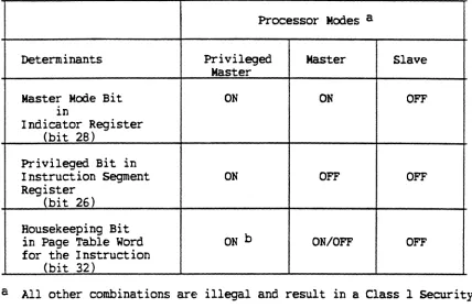
Status Of Processor Mode Determinants •••••••••••••••••••••••••• Ranges Of Fixed-Point Numbers •••••••••••••••••••••••••••••••••• Ranges Of Binary Floating-Point Numbers •••••••••••••••••••••••• Processor Accessible Registers ••••••••••••••••••••••••••••••••• System Controller Illegal Action Codes ••••••••••••••••••••••••• SOurce Of Fault Register Errors •••••••••••••••••••••••••••••••• Address Modification Octal Codes •••••••••••••••••••••••••••••••
(
(
Table
6-2 6-3 7-1 7-2 7-3 7-4 7-5 8-1 8-2
A-I
A-2
"l'ABLBS (amt)
Processor Modes •••••.•..••••••.••••••.••.•.•••••••.••••••.•••••
Classes Of Faults And Interrupts (DPS 8000) •••••••••••••••••••• Alphanumeric Character Number (CN) Codes ••••••••••••••••••••••• Alphanumeric Data Type (TA) Codes •••••••••••••••••••••••••••••• Sign And Decimal Type (S) Codes •••••••••••••••••••••••••••••••• Default Edit Insertion Table Characters For MVE And MVNX •••••••
Edit Insertion Table Entries For MVNEX •••••••••••••••••••••••••
Binary-To-BCD Conversion Constants ••••••••••••••••••••••••••••• Character Codes For ASCII And EBCDIC Overpunched Signs ••••••••• Operation Code Map (Bit 27
=
0) •••••••••••••••••••••••••••••••• Operation Code Map (Bit 27=
I} ..•..•...•.•....•..•...•..•.xv
---- - -
-Page
6-10 6-26 7-27 7-27 7-32 7-39 7-40 8-78 8-398 A-2 A-4
(
(
(
SPa'lOIi 1
I lI"1'ROOOC'.rI 011
This manual contains a set of machine instructions used on Honeywell Bull hardware and operating systems. The systems are highly modular, allowing system configuration to be matched to the work load mix. This section describes the essential characteristics of the central processors for these systems.
Each processor module in the system has full program execution capability. The processors conduct all actual computational processing (data movement,
arithmetic, logic, comparison, and control operations) within the information system. The processor communicates only with the system controller (DPS 8000: SCU, System Control Unit) and associated memory. The processors contain several special features that make significant contributions to multiprogramming, high throughput, and rapid turna~ound. These features are under the control of the operating system which maintains automatic supervision and complete control of the multiprogramming/multiprocessing environment.
PROCFSSOR FEATURES
A processor contains the following general features:
1. Memory protection to place access restrictions on specified segments
2. capability to interrupt program execution in response to an external signal (e.g., I/O termination), to save processor status and to restore the status at a later time without loss of program continuity
3. capability to fetch instructions and to buffer instructions
4. A four-stage pipelined instruction development for greater performance
5. Fully interlaced store units addressable by a given SCU
6. Ability to hold recently referenced operands and instructions in a 64K high-speed cache memory
7. An Extended (ES) mode that uses 36-bit addressing includes a set of
general register-to-register instructions
8. Real memory configurations of up to 256 megawords are supported.
9. Quad-precision arithmetic operations for which the exponents are handled as powers of 16
Pipeline Architecture Of 1'he DPS BOOO
The four-stage pipeline processor consists of the following cycles:.
A cycle: Effective address calculation and virtual address calculation are
performed
V cycle: Virtual address to real address translation and bound checking, access checking (read, write permission, etc.) are performed
C cycle: Memory is accessed (cache) using the real memory addresss
E cycle: Instruction is executed by firmware control
One instruction execution completes via four cycles. The maximum instruction rate is attained when the processor is executing basic instructions (one memory access and one execution cycle). Because the processor operates as a
four-stage pipeline, a new instruction can be issued before the prior one is completed, thereby reducing the effective execution time.
Faults And Interrupts
The processor detects illegal instruction usages, faulty communication with main memory, programmed faults, certain external events, and arithmetic
faults. Many of the processor fault conditions are deliberately caused by the software and do not necessarily involve error conditions. The processor
communicates with the other system modules (1/0 processors and other
processors) by setting and answering external interrupts. When the processor responds to a fault or interrupt, control is transferred to an operating system module via an interdomain transfer using an entry descriptor obtained from a fixed memory location.
The locations in real memory containing the entry descriptors for interrupt, faul t, and system entry (PMME) are as follows;
Interrupt
Fault
System Entry
Location
30-31 (octal)
32-33 (octal)
(
Interrupts and certain low-priority faults are recognized only at specific times during program execution. If, at these times, bit 28 in the instruction word is s~t ON, the trap is inhibited and program execution continues. The interrupt or fault signal is saved for future recognition and is reset only when the trap is recognized.
ConnectlInterrupt Mechanism
On a connect to the IMX, the software points to a logical channel mailbox that
resides anywhere in main memory. The mailbox is required to be 24 words, beginning at a 0-modulO-8 address. The operating system is responsible for placing specific information into the first eight words.
This mailbox serves as the primary intercommunication vehicle between the IMX and the CPU. SOftware specifies the (relative) starting location of the
mailbox as the effective address of the connect instruction (crOC). Normal CPU address preparation converts this to a real memory address, which is then used by the IMX.
Successi ve I/O operations to the same logical channel can be issued via a linked mailbox feature available through IMX's. However, once a connect has been issued by the software, it is the responsibility of the operating system to not issue another connect directed to the same logical channel until the current one is completed or a "lost interrupt" timeout has occurred.
All 128 channels (numbered 0-127) are data channels except channel numbers zero and three. Channel three is used for two-way communication between the CPU and IMX maintenance system (MCA). Channel zero is normally declared invalid, to avoid confusion that would otherwise exist in the operating system as to
whether a given channel number field is zero, or the field is currently unused.
The CPU automatically directs the connect command to the "control" SCU. If the system configuration includes two SCU's (i.e., tandem), then the SCU which is designated as "control" is the one which processes all connects and interrupts for the operational system. The control' SCU then adds a connect word pair to the destination port's connect queue and notifies the port that a connect is present in its queue. The IMX reads the contents of the queue with the Read Connect Words command instruction (RCW).
An interrupt queue mechanism is used in the DPS 8000 system that allows for up to 256 simultaneous entries for each of eight interrupt levels. Thus, the SCU maintains a queue for each interrupt level. Levels one and seven are for fault and special interrupts, respectively. The interrupt level for marker/terminate interrupts are specified at connect time in the mailbox (GeOS uses levels 5 and 3, respectively).
The control SCU sends an interrupt present signal to all CPU's that are unmasked for this interrupt level (each CPU initializes and modifies its own masks independently). The SCU sends an accept signal to the candidate CPU selected, and automatically shuts off all further interrupt present signals by masking a unique system-wide "all mask".
The CPU, selected by the SCU to process the interrupt, transfers to the
operating system interrupt handler by executing an interdomain CALL version of
the CLIMB instruction, using the entry descriptor at location 30-31 (octal). / The software interrupt handler uses the RIW instruction for each pair of
interrupt words (one doubleword interrupt queue entry). The next interrrupt pair is selected from the highest priority (Le., lowest numbered), unmasked level, and inserted into the AQ register. When no more entries are available at any level that is unmasked for this CPU, then the AQ register will contain all zeros.
The operating system examines the channel mailbox for status information. On terminate or marker type interrupts, status returns are automatically stored in the channel mailbox. Up to eight words of peripheral extended status are
likewise stored.
Online Processor Tests
The PATROL feature (Processor Activity Test Runs On Line) is implemented as firmware in its own unique CPU memory. PATROL runs test programs and reports status to the maintainance interface.
OPERA'l'IHG MODES
Three types of modes determine the operation of the CPU.
o Pri vileged Master, Meister, and Slave modes which determine the processor
JKXie of operation ,/'"
o BS and ES (Hon-extendedlExtended) modes which determine whether lS-bit or 36-bit registers are used and determine the method to be used to generate effective and virtual addresses
o Memory addressing modes
Processor Modes Of Operation