International Conference “
INTELINC 18
”, 12
& 13
October 2018
Real-Time Area Efficient and High Speed Architecture Design
of Huffman Decoder
Venkat Narayana .T
1, Y. Rama Lakshmanna
2, V.Yaswanth Varma
3, D.V.R Mohan
4,K.H.S. Suresh Kumar
51,2,3
Associate Professor, 4Professor, 5P.G Student
Department of ECE, SRKR Engineering College, Bhimavaram, India ¹,2,3,4,5
Abstract—In this paper, An area efficient and high speed design and architecture of Viterbi Decoder with encoded rate of 1/2 and with a constraint length of k = 3 is taken for the application in satellite communication and wireless communication. Generally, the data transmitted over any communication channel is affected due to noise. So, for detection and correction of the errors occurred due to channel noise, Encoding and decoding should be performed at the transmitter and receiver end respectively. The Viterbi Algorithm is one of the most popular algorithms for decoding convolution codes. Using VLSI technology, the system requires less area and high speed constraints while designing. A high-speed Viterbi decoder is a challenging task Due to the recursive iteration of various steps followed for Decoding process. In this paper, performance comparison of Viterbi decoder and Huffman decoder along with their Performances have been discussed.
Keywords—viterbi decoder,huffman decoder, VLSI style
1. INTRODUCTION
Now-a-days most of the digital communication systems convolutionally encodes the transmitted data to compensate for various noises. For its efficiency the Viterbi algorithm has proven to be a very efficient algorithm for forward error correction of convolutional encoded messages. The Viterbi decoding algorithm was proposed by A.J Viterbi. There has been an increased interest in high-speed Viterbi decoder design within a single chip. Advanced field programmable gate array (FPGA) technologies and well developed electronic design automatic (EDA) tools have made it possible to realize a Viterbi decoder with the throughput at the order of Giga-bit per second, without using off-chip processor(s) or memory. The algorithm can be applied to a host of problems encountered in the design of communication systems. The Viterbi Algorithm finds the most-likely state transition sequence in a state diagram, given a sequence of symbols. The Viterbi algorithm is used to find the most likely noiseless finite-state sequence.[1] [2]
It is well known that data transmissions over wireless channels are affected by attenuation, distortion, interference and noise, which affect the receiver„s ability to receive correct information. Convolutional encoding with Viterbi decoding is a powerful method for forward error detection and correction. It has been widely deployed in many wireless communication systems to improve the limited capacity of the communication
channels.[1][2]
Fig.1.Convolution Encoder
2.
CONVOLUTIONAL ENCODER:
There are applications in which the message bits come in serially in place of in massive blocks, Where in case the use of a buffer may be undesirable. In such situations, the use of convolutional coding may be the desired technique. A convolutional coder generates redundant bits with the aid of usage of modulo-2 convolutions-subsequently the name of the coder . The convolutional encoder can be represented as a finite state machine (FSM) with given number of shift register stages, e.g. if there is an K-stage shift registers with rate of encoder input bits to its output is 1/n and a L bit length message; the coded output sequence will have length of n (L+K) bits.[1] [2]
Also the code rate of the convolutional code is therefore given by: = L bits/symbol n(L + K)
(Because L >> K) This rate always reduced to: ≈ 1
Viterbi decoder:
International Conference “
INTELINC 18
”, 12
& 13
October 2018
processing the sequences on an information bit-by-bit(branches of the trellis) basis. In other words, instead of keeping a score of each possible coded sequence, the VD tracks the states of the trellis.
Viterbi algorithm performs ML decoding by reducing its complexity. It eliminates least likely trellis path at each transmission stage and reduce decoding complexity with early rejection of unlike pathes. Viterbi algorithm gets its efficiency via concentrating on survival paths of the trellis. The Viterbi algorithm is an optimum algorithm for estimating the state sequence of a finite state process, given a set of noisy observations[3]
The implementation of the VA consists of three parts: branch metric computation, path metric updating, and survivor sequence generation. The path metric computation unit computes a number of recursive equations. In a Viterbi decoder (VD) for an N-state convolutional code, N recursive equations are computed at each time step (N = 2k-1, k= constraint length). Existing high-speed architectures use one processor per recursion equation. The main drawback of these Viterbi Decoders is that they are very expensive in terms of chip area. In current implementations, at least a single chip is dedicated to the hardware realization of the Viterbi decoding algorithm the novel scheduling scheme allows cutting back chip area dramatically with almost no loss in computation speed.[3]
Fig. 2. Block Diagram of Viterbi decoder
Generally, a Viterbi decoder consists of three basic Computation units.
1. Branch Metric Unit (BMU) 2. Path metric unit (PMU) and 3. Trace Back Unit (TBU)
1
.Branch Metric Unit (BMU):
A branch metric unit's function is to calculate branch metrics, which are normed distances between every possible symbol in the code alphabet, and the received symbol.
[
4]
There are hard decision and soft decision Viterbi decoders. A hard decision Viterbi decoder receives a simple bit stream on its input, and a Hamming distance is used as a metric. A soft decision Viterbi decoder receives a bit stream containing information about the reliability of each received symbol.[4] The squared Euclidean distance is used as a metric for soft decision decoders.
Fig. 2.1
Block diagram for BMUFigure 2.1, it will represent the block diagram for BMU. v1, v2 represent a symbol where v1 and v2 is two bit of symbol. Normed or Hamming Distance is calculated with help of two Xor gate and 1 Half Adder.[4]
2. Path Metric Unit (PMU):
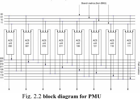
Fig. 2.2
block diagram for PMUA path metric unit summarizes branch metrics to get metrics for 2K − 1 paths, one of which can eventually be chosen as optimal. Every clock it makes 2K − 1 decisions, throwing off wittingly non optimal paths. The results of these decisions are written to the memory of a trace back unit.[5]
In Path Metric Unit “Add Compare and Select Unit”, are arranged in particular fashion based on formation of Trellis Diagram.
2.1 Add Compare Select Unit(ACSU):
The core elements of a PMU are ACS (add-compare-select) units. The way in which they are connected between themselves is defined by a specific code‟s trellis diagram
Fig. 2.2.1
Block diagram for ACSU [image:2.595.309.555.252.426.2] [image:2.595.311.558.575.657.2]International Conference “
INTELINC 18
”, 12
& 13
October 2018
from the earlier stage, there are two possible path metricscoming to the current state. The ACS unit, as shown in figure 2.1, adds for each of the two incoming branches the corresponding states path metric, resulting in two new path metrics. The path with the better metric is chosen and stored as the new path metric for current state, while generating a decision bit. After decoding it has to give in the same sequence but in the reverse order i.e. we are getting as a decoded sequence.[6]
The decision bit indicates what branch was chosen. Because each state can be achieved from two states from the earlier stage, the decision value is represented by one bit. If the bit is one the path metric selected is coming from the lower state from those two possible states in Trellis diagram, and if the decision bit is zero the path metric selected is coming from the upper state. As the ACS unit needs the results from the calculations of the previous steps, it forms a feedback loop with the external memory unit, where the results are stored.[6]
3. Trace back Unit (TBU):
The trace back approach is generally a lower power alternative to the register exchange method. In trace back, one bit for the local winner is assigned to each state to indicate if the survivor branch is from the upper or the lower position. Using this local winner, it is possible to track down the survivor path starting from a final state and this search is enhanced by starting from a global winner state as previously discussed.
Figure 2.3 shows a trace back SPU architecture adapted from the architecture described in which used global winner information. Here, local winners are stored in the local winner memory
Trace back is started at the global winner from the PMU, which is used as an address to read out the local winner of the global winner state.
Then, in the trace back logic the previous global winner in the trace back is produced by shifting the current global winner one place to the right and inserting the read out local winner into the most significant bit position; this arithmetic relationship between parent and child states derives from the connection shown in Figure 2.3.
[image:3.595.317.545.121.222.2]This new global winner can then be stored into the global winner memory to update the global winner existing at that time slot. The process repeats with the updated global winner reading out its local winner which is used to form the global winner for the previous time slot. This process continues until the global winner formed agrees with that stored or it reaches the oldest time slot. In the output logic, shown in Figure 2.2, the decoded output can be obtained from the least significant bit of the global winners stored in the global winner memory.
Local and global winners are stored in memory. So for each trace back, local winners are repeatedly read out from the
local winner memory and new global winners are written back to
Fig. 2.3
Trace back implementation using memory the global winner memory. This results in complex read/write control mechanisms. Furthermore, unless flip flop storage is used then multi-port SRAM blocks are required. Moreover, it is preferable to run trace backs in parallel as an incorrect trace back may damage a “good” path and it needs a new trace back to correct this as soon as possible.Viterbi decoder algorithm design flow
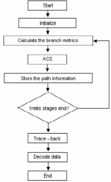
:The below shows the flow chart for the Viterbi decoder algorithm design flow.
Fig. 3.
Viterbi decoder algorithm Design flow The algorithm can be broken down into the following three steps. [image:3.595.339.520.343.638.2]International Conference “
INTELINC 18
”, 12
& 13
October 2018
2. Recursively computes the shortest paths to time n, in termsof the shortest paths to time n-1. In this step, decisions are used to recursively update the survivor path of the signal. This is known as add-compare-select (ACS) recursion.
Recursively finds the shortest path leading to each trellis state using the decisions from.
3. The shortest path is called the survivor path for that state and the process is referred to as survivor path decode. Finally, if all survivor paths are traced back in time, they merge into a unique path, which is the most likely signal path. [7]
Viterbi decoder RTL Design using VHDL Style:
[image:4.595.312.496.92.364.2]Reports of Viterbi decoder:
Table 1: Advanced HDL Synthesis Report:
Huffman coding:
Here use Huffman's algorithm [6] to construct a tree that is used for data compression. Here discuss how to construct the tree
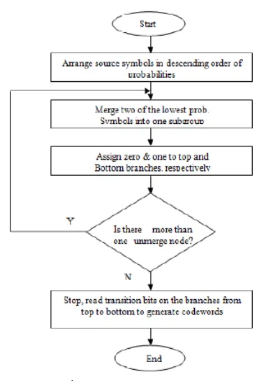
The below flow chart shows the Huffman coding flow chart. .
Fig. 4. Huffman coding flow chart
Aassume that each character has an associated weight equal to the number of times the character occurs in a file. The
technique works by making a binary tree of nodes.[6][8][9] A node can be either a leaf node or an internal node. Initially, all nodes are leaf nodes, which contain the symbol itself, the weight (frequency of appearance) of the symbol and optionally, a link to a parent node which makes it easy to scan the code (in reverse) ranging from a leaf node. Internal nodes contain a weight, links to two child nodes and an optional link to a parent node. As a common convention, bit '0' represents following the left child and bit '1' represents following the right child. A finished tree has up to leaf nodes and internal nodes. A Huffman tree that omits unused symbols produces the most optimal code lengths.
The process begins with the leaf nodes containing the probabilities of the symbol they represent. Then, the process takes the two nodes with smallest probability, and creates a new internal node having these two nodes as children. The weight of the new node is set to the sum of the weight of the children. We then apply the process again, on the new internal node and on the remaining nodes, we repeat this process until only one node remains, which is the root of the Huffman tree.[10][11][12]
Proposed Huffman decoder:
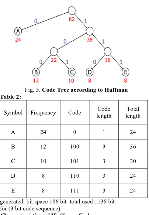
The following example bases on a data source using a set of five different symbols shown first two columns in table 2.Total 186 bits (with 3 bit per code word).
International Conference “
INTELINC 18
”, 12
& 13
October 2018
frequency 16 and 22 respectively and are brought together inthe next step. The resulting node and the remaining symbol 'A' are subordinated to the root node that is created in a final step.[8] [9][10]
[image:5.595.37.282.145.499.2] [image:5.595.36.299.618.715.2]Code Tree according to Huffman
Fig. 5. Code Tree according to Huffman Table 2:
Symbol Frequency Code Code length
Total length
A 24 0 1 24
B 12 100 3 36
C 10 101 3 30
D 8 110 3 24
E 8 111 3 24
generated bit space 186 bit total used . 138 bit for (3 bit code sequence)
Characteristics of Huffman Codes:
Huffman codes are prefix-free binary code trees, therefore all substantial considerations apply accordingly
Codes generated by the Huffman algorithm achieve the ideal code length up to the bit boundary. The maximum deviation is less than 1 bit.[8][9][10]
Table 3:
Symbol P(X) I(X) Code
length H(X)
A 0,387 1,369 1 0,530
B 0,194 2,369 3 0,459
C 0,161 2,632 3 0,425
D 0,191 2,954 3 0,381
E 0,191 2,954 3 0,381
theoretical minimum: 2,176 bit code length Huffman: 2,226 bit
The computation of the entropy results in an average code length of 2.176 bit per symbol on the assumption of the distribution mentioned. In contrast to this a Huffman code attains an average of 2.226 bits per symbol. Thus Huffman coding approaches the optimum on 97.74%.
Table 4: Area utilization of Huffman decoder
International Conference “
INTELINC 18
”, 12
& 13
October 2018
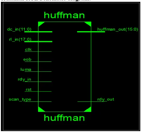
Huffman RTL Schematic diagram:
Fig. 6. RTL Huffman decoder
Table 5 :Comparison of results of Huffman and Viterbi decoder for the better technique for the area utilization and time delay.
Technique Viterbi decoder Huffman decoder
Area 93(µm)² 37(µm)²
Time delay 4.241ns 0.640ns
Frequency 235.78MHz 120.60MHz
3.
CONCLUSION:
On the basis of obtained results, concluded that Huffman coding has the lesser area utilization and less time delay when compared with the Viterbi decoder. By observing the obtained results for both the Viterbi and Huffman decoder‟s. Huffman decoder was the better decoder than the Viterbi decoder.
4.
FUTURE SCOPE:
Future scope of this paper obtained by considering Adaptive Huffman decoder which may achieve better results in area utilization and diminishes time delay.
REFERENCES:
[1] Amruta J. Mandwale,Altaf 0.mulani,”Implementation of high speed Viterbi decoder using FPGA”, International Journal of Engineering Research & Technology (IJERT),ISSN:2278-01881,vol.5,Issue-02,Feb 2016.
[2] Amruta J. Mandwale ,”Different Approaches for Implementation of Viterbi Decoder on Reconfigurable Platform”, International Journal of Engineering Research & Technology (IJERT),ISSN: 2278-0181 IJERTV3IS110327 Vol. 3 Issue 11, November-2014
[3] Amitesh baghel,Abdeal patanwala,jayjoshi,”A study on advanced data security for sustaining compititive edge”, International Journal of Engineering development and research (IJEDR),ISSN:2321-9939,vol.5,Issue-2,2017.
[4] FPGA Implimentation of soft decision low power convolutional decoder using veterbi algorithem from https://www.slideshare.net
[5] www.ijitr.com/index.php/ojs/articles
[6] Beeram raj mohan reddy,Bellam varalakshmi,”FPGA Based Efficient Implementation of Viterbi Decoder”,International journal of computer Engineering in research trends (IJCERT), ISSN:2349-7084,vol-02,,Issuue-12,December-2015. [7] Anubhuti Khare,manish saxena,jagadish
patel,”FPGA based efficient implimentation of viterbi decoder”,International Journal of engineering and advanced technology (IJEAT),ISSN:2249-8958,vol-1,Issue-1,October-2011
[8] Ksenija Lakovic, John Villasenor and Rick Wesel, “Robust Joint Huff man and Convolutional Decoding”, 0- 7803-5435-4/99/$10.Q00 1 999 IEEE, VTC „99
[9] Heonchul Park and Viktor K. Prasanna. “Area Efficient VLSI Architectures for Huffman Coding” , IEEE TRANSACl2ONS ON CIRCUITS AND SYSTEMS-11: ANALOG AND DIGITAL SIGNAL PROCESSING, VOL. 40, NO. 9, SEPTEMBER 1993
[10]Joseph Lee, “Huffman Data Compression”, MIT Undergraduate Journal of Mathematics.Swapna R and Ramesh P. “Design and Implementation of Huffman Decoder for Text data Compression”, International Journal of Current Engineering and Technology E-ISSN 2277 – 4106, P-ISSN 2347 – 5161.
[11]Rakhi B Menon ,Dr.Gnana Sheela K,”Design an d Implimentation of Convolutional encoder an d Viterbi decoder”,International Journal of computer science and network v4 i76
[image:6.595.35.273.103.323.2]