Abstract—Launching of Rocket is a complex phenomenon. There is high chance of failure in such missions. Hence it is necessary to predict the launch path or Trajectory, External disturbances and various other parameters. Numerical Simulation is one such way of predicting launch parameters which helps in taking precautions preventing failure. This Paper presents a platform for simulation of Rocket launch vehicle and control Law validation. The analysis is performed during the Lift-off phase in atmosphere using a mathematical nonlinear dynamic model. Set of six degrees of freedom equations of motion with necessary reference frames and transformations in between them is developed. The Mathematical Model is applied in MATLAB and Simulink simulation which can be easily adjusted for any type of launch vehicle or rocket.
IndexTerms— Simulation of Rocket Launch Vehicle,
Mathematical model, Numerical Simulation, Six degree of freedom equation of motion.
I. INTRODUCTION
Safe Transport of any kind of payload to an orbit around the Earth using a launch vehicle is the ultimate goal. The Payload of these Rockets mostly comprises of highly valuable Satellites, deep space probes and some even serve for manned missions to the Moon and International Space Station. Therefore development and reliability of carrier rocket is necessary.
Advancements in Aerospace Industries were mainly due to its application in Military, Research and many different fields in modern history. The fastest advancements took place during the cold war between USA and USSR resulting in landing of man on the Moon. We have never stopped exploring our surroundings, by launching Hubble space telescope to study deep space and neighbouring Galaxy, Elon musk’s SpaceX company has successfully tested its Falcon Heavy by launching Tesla Roadster safely into an orbit in space, Indian Space Research organisation (ISRO) successfully placed an satellite in Mars orbit and plans to land
Manuscript revised May 13, 2019 and published on June 5, 2019
Dhanush G J, Final Year Student, Department of Aeronautical Engineering, S J C Institute of Technology,, Chikkaballapur, India
Ajith Patil J R, Final Year Student, Department of Aeronautical Engineering, S J C Institute of Technology,, Chikkaballapur, India Deepak B S, Final Year Student, Department of Aeronautical Engineering, S J C Institute of Technology,, Chikkaballapur, India Manjunath, Final Year Student, Department of Aeronautical Engineering, S J C Institute of Technology,, Chikkaballapur, India
DEEPA M S, Associate Professor, Department of Aeronautical Engineering, S J C Institute of Technology,, Chikkaballapur, India
a Rover in the near future and Jeff Bezos with his company Blue Origin is planning to open space exploration to the public. Hence aerospace industry is developing at a faster phase than ever.
Design and manufacture of rockets has its own complications and certain steps must be taken before we start the physical processes occurring during an atmosphere and space flight. This paper is aiming to develop a mathematical model of rocket launch vehicle during lift-off phase in Earth’s atmosphere. This is done by defining various reference frames involving the launch vehicles environment. Kinematic and Dynamic models of rocket are developed to obtain set of equation of motion. Also individual sub-models are used and described.
The mathematical model is taken as the basis for the computer simulation development. MATLAB is utilized along with Simulink Tool to create an interactive and accurate simulation of launch vehicle flight.
II. MATHEMATICAL MODEL
A. Reference Frames: To describing the position and motion of the launch vehicle, several reference frames in accordance to Ziphel[1]are introduced. Reference frames are right handed Cartesian coordinate systems specified by their orientation in space. Certain relation between various frames is to be derived in order to obtain complete characterization of launch vehicle’s motion.
Earth Centred Fixed Reference Frame [ECI]:
Centre of the earth is considered to be the origin with , , and as their basis vectors. Vector lies in the equatorial plane pointing towards the vernal equinox in J2000 epoch.
Vector is normal to the equatorial plane, coinciding with Earth’s axis of rotation pointing towards North Pole. Vector lies in the equatorial plane and completes the right handed Cartesian system.
Earth Centred Fixed Reference Frame[ECF]:
Centre of the Earth is taken as Origin with its basis vectors
e, e and e. Vector e is pointing from the centre of the
earth to the intersection of the Earth’s prime Greenwich meridian with the equator. Vector e is aligned along the
Earth’s spin axis and thus coincides with ECI’s basis vector
Numerical Simulation of Rocket Launch Vehicle
198 . Vector e completes the right handed Cartesian coordinate
system.
The relation between ECF and ECI is given by,
(1)
Earth Geographic Reference Frame[EG]: This frame can be
used to describe an position on the surface of the Earth. Longitude is Positive from Greenwich meridian to the East and Latitude is positive from the Equator to the North. The origin can be on any point on Surface of Earth with its basis vectors g, g and g.Vector g is normal to the Earth’s
surface pointing upward, vector g points towards North and
, g points towards east.
Transformation from ECF to EG is given by,
(2)
Body Reference Frame[B]: This reference frame is used to describe the relative attitude of the launch vehicle with respect to its initial position at the launch pad and is the basis for the reference points inside the vehicle. The body reference frame has the basis vectors b, b and b . Origin of
the frame lies within the centre of gravity or centre of mass. Vector b is aligned with the body main symmetry axis
pointing towards the rocket’s nose. Vector b aligned with
right fin of the Rocket and b is pointing downwards to
[image:2.595.325.536.120.204.2]complete the triad.
Figure 4: Body Reference Frame
The Transformation matrix from geographical to body frame can be expressed by,
(3)
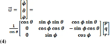
C. Rotational Kinematics: The reference frames and Transformation matrix will provide the position of the launch vehicle in space. In order to obtain the orientation of the launch vehicle the Pitch, roll and yaw angle is necessary. An angular velocity is introduced as a derivative of the YPR
angles. The total angular velocity of launch vehicle as shown by Wie[3] is given by,
(4)
But using the above equation causes problems, as there is a chance for Euler angles to have singularity at some point i.e. at pitch angle θ = where k
ϵ
Z because of cosine function in denominator of fraction. Such singularity is called as Gimbal Lock, which is term used to define a mechanical phenomenon when two axes of rotation coincide causing the system to lose sense of on degree of freedom.[4]. In order to avoid gimbal lock quaternions are used. Use of quaternions in computer simulation has great advantage as it reduces the computation time to greater extent.The rotational kinematic equation (4) has its equivalent in quaternions [1] given by,
(5)
Finally the Euler angles representing yaw, pitch and roll rotation is obtained back from quaternions notation by three equations,
(6)
(7)
(8)
C. Equation of Motion: The dynamics of the launch vehicle is given by the equation of motion. The dynamics of launch vehicle is described accommodating six degree of freedom is divided into two parts, the Translational and Rotational movement.
The Translational Dynamics takes the first three degrees of freedom Using the Newton’s law and sum of all external forces acting on the launch vehicle, considering atmosphere, gravity and propulsion. With appropriate transformations, we can express the differential equation as,
(9)
pitch and roll angles of the launch vehicle. The three main sources of forces and torques acting on the spacecraft are – atmosphere, gravity and propulsion. Since gravitational force is acting from centre of gravity, no torque is produced. The aerodynamic and propulsion force moments have different reference points. The total angular acceleration of the launch vehicle is given by,
(10)
III. SUBSYSTEM MODELS
In the previous sections we have come across two sets of equations that influence the flight of the launch vehicle. The first set of equations gives us the forces and launch vehicle translational motion in space. The second set of equations gives us the moment exerted on the launch vehicle and its effect on attitude dynamics. This section will introduce factors influencing the Mathematical model considered above.
[image:3.595.321.522.127.250.2]Gravity: Earth is considered to be an ideal sphere which is not the accurate assumption. The planet is flattened on the poles resembling an ellipsoid. The best word describing the Earth’s shape is a geoid. The geometric estimation of Earth’s shape is given by the World Geodetic 1984model[8]. The reason for considering this model is to describe the variation of Gravitational magnitude based on Earth’s location. The various constants of the ellipsoid is as shown in table,
Table 1. WGS84 ellipsoid constants
Quantity Symbol Value
Semi-major axis a 6,378,137.0 m Mean radius Rm 6,371,008.8 m
Flattening f 1/298.257223563
Gravitational constant
µ 3,986,004.418
m3s-2
Eccentricity e 0.08181919084
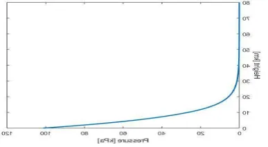
Atmosphere:During the lift-off phase the rocket experience various forces and moments as it travels through distinctive layers. The atmospheric conditions vary with height and are never the same. This variation must be considered in our mathematical model in order to obtain accurate results. The parameters
considered are Air density, Air pressure and Air temperature. Simplified calculations based on the U.S Atmosphere 1976 model[8] is used. The following graphs
Figure 4: Variation of Atmospheric pressure
shows variation of Pressure, density and temperature with varying height
[image:3.595.332.523.334.482.2]Figure 5: Variation of Atmospheric Density
Figure 6: Variation of Atmospheric Temperature
IV. SIMULATION
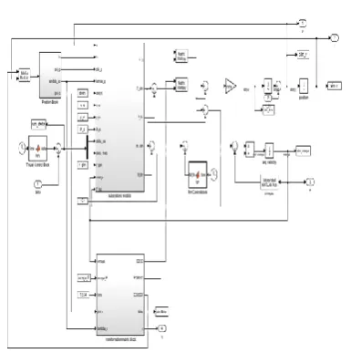
Based on the equations we obtained in Mathematical model and also considering the effects of subsystem models which include Gravity and Atmospheric effects, a Simulink model is created. The main equations considered for this model are equations (5), (9) and (10).
[image:3.595.71.265.692.798.2]200
FIGURE 7:SIMULINK MODEL
The Simulink model is designed in a way to allow future extensions in its application. The simulation is run for 200 seconds by default with the burn time set for 162 seconds.The simulation run time can be adjusted to any value as needed.
Input Data:The simulation model that is designed using the mathematical model comprises of variables that needs substitution of real data. Ultimately the Output obtained must be a definite numerical value which can be modified as per our needs and displayed in various graphs and figures a user can understand. Most of the input data has been taken from Falcon 9 FT launch vehicle of SpaceX private company
[12][13]114]
[image:4.595.314.541.84.219.2]and few other data are approximated due to its accurate data unavailability.
Table 2. Simulink model Input Data
Quantity Symbol Value
EARTH DATA
Angular velocity of Earth
ѡE 7.2921 x 10 -5
rad/s
Initial Geocentric Latitude
Φcinit 00
Initial Geocentric Longitude
ʎcinit 00
Initial launch vehicle Position
rinit [6378137; 0; 0]
m
LAUNCH VEHICLE DATA
Payload mass Mp 20,000 kg
Launch Vehicle mass
Mlv 5,50,000 kg
Main Moment of Inertia
J11, J22,, J33 1.2 x 10 5
, 2.1 x 10⁷, 2.1 x 10⁷ Launch vehicle
length
d 70m
ENGINE DATA (MERLIN 1D)
No of Engines n 9
Specific Impulse ISP 282 s
Total Thrust T 8,45,000 x 9 N Burn time tburn 162 s
Exit Velocity Ve 251 m/s
Mass Flow rate 280 kg/s
Exit pressure Pe 9 x 10⁵ Pa
Nozzle Exit Area
Ae 0.97 m2
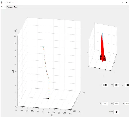
V. RESULTS
After running the Simulation model most of the output is stored in MATLAB Workspace with its variable names. Most of the variable names are in the format ‘sim_(quantity name)’. Our mathematical model consists of several accurate sub models, due to which accurate results are obtained. However, the launch vehicle behaviour varies extensively as the aerodynamic coefficients do not remain constant throughout the flight. The coefficients value depends on velocity of air and such complexity is beyond the capability of our work.
Figure 8: Thrust over time Plot Figure 9: Launch vehicle Flight trajectory
[image:4.595.73.266.111.305.2] [image:4.595.319.551.380.545.2]Figure 11: MATLAB GUI – Atmosphere
Figure 12: MATLAB GUI – Thrust
Figure 12: MATLAB GUI – Thrust
.
VI. CONCLUSION
Number of books is written about Rocket and Rocket Launch vehicle flight laws and it is not feasible to cover the problematic in its whole depth and width in this paper. A satisfactory mathematical model was developed and platform for simulating rocket flight has been described in this work.
Number of equations was obtained in the mathematical model along with the effects of sub system models. These equations were later incorporated in the Simulink model and the initial data was considered from various sources and few values were approximated in order to complete the simulation.
An analysis script and a GUI script were written and run in MATLAB to obtain results in a way users can easily understand and implement.
In order to validate this model a Water rocket experiment can be performed and comparison study be made to prove that this simulation is accurate
REFERENCES
[1] Peter H. Zipfel. Modeling and Simulation of Aerospace Vehicle
Dynamics. 2nd. AIAA, 2007. isbn: 9781563478758.
[2] International Earth Rotation and Reference System Service. Bulletin B
344. 1.10.2016.
[3] Bong Wie. Space Vehicle Dynamics and Control. 2nd. AIAA, 2008.
isbn: 9781563479533.
[4] James Diebel. Representing attitude: Euler angles, unit quaternions, and rotation vectors. In: Matrix 58 (2006).
[5] Wei Du. Dynamic modeling and ascent Flight control of Ares-I Crew
Launch Vehicle. Iowa State University, 2010
[6] National Imagery and Mapping Agency. World Geodetic System 1984.
3rd. NIMA, 3.1.2000.
[7] Robert F. Stengel. Flight Dynamics. Princeton University Press, 2004.
isbn: 0691114072.
[8] National Oceanic Atmospheric Administration, Department of the Air
Force, and NASA. U.S. Standard Atmosphere, 1976. 1976.
[9] The Beginner's Guide to Aeronautics. url:
https://www.grc.nasa.gov/WWW/K12/airplane/ac.html
[10]Filip Svoboda. Research report: Water rocket project. Czech Technical University, 2015.
[11]Warrick Miller. Lecture notes: Space Vehicle Design (MECH ENG 3104). The University of Adelaide, 2016.
[12]Space Exploration Technologies Corp. Falcon 9 Launch Vehicle Payload User's Guide, Rev 2. SpaceX, 2015.
[13]Falcon 9 FT. url: http : / / spaceflight101 . com / spacerockets / falcon - 9 - ft/
[14]Saturn V Launch Simulation. url:
http://www.braeunig.us/apollo/saturnV.htm .