..
L--.:t7
1 '~7/Jet ember
A
Digital COlllputer for Scientific
Applications·
t
\\'ESTt,
MEMBER, -IRE, A~DJ.
E.
DETURKt
SummarJt-Durmc the past two y~.n development has been initiated on several large-scale automatic dacltel computinc machinel, both in this country and abroad. The present paper is concerned with the over-all orcanization of one such machine. A locicaJ division of the machine into four major components is described, and the ma-chine performance is interpreted in terms of these component func-tions. The electronic techniques used to accomplish the storace, transmission, and arithmetic manipulation of numbers, tocether with certain methods used for control of the computer, are briefly discussed. Although the paper is concerned with the desi.cn of a particular machine, it is felt that the desicn problems and encineerinc techniques are applicable to most larce-scale computinc machines.
.1. I ~T i{ODtTTlOS
1
~ ifF: TER\I "digital computer" applies. to a calcu-lating- machine in which a numix'r can assume only a discrete \'alut' the pn.'cision of which is determined by tilt' numht'r of digits lISt'd for its repre-sentation. :\ desk calculator is ;; digital (or discrete-\'ariableJ computer, wht.'rt'~t" a slidt> rult, is a continuous-\'ariable computer. .\ laq;e-scale digital computer is a machine not onl" capahle of digital computation, but one which can pc·d, )rm long sequences of computations in accordance wi t h a pre-estahlished program of opera-tion. \Jachim's of this tyPt' are al~() relt'rred to as' se-qlwn('e-('ontroll('d calclllators, Such a comp"tt'r is ca-p.l hIe of sol "ing complt,\. prol,\el1l" ill \'oh·im.: t hOlls;! nds or millions of, indi"id lJal arithml't ic opt'r;Jtions wi t houtthe intervention of a human olwrat()r,
Large-scale comput{'rs may be <iiyidt'd roughly into two categories: Scientific machint,s which are designed to perform largl' n umht'rs of cakub t ions baSt'd upon relative\y few input data and yidding relatin'\y few output data, and statistical rnachirws of which the opposite is trUt·. Th(' calcubtor to he describeo is in-tended primarily for scit'll t i fit: applil-ations. Some of the types of problems which the presc'nt machine is intended to solvc are the following:
(1) The systematit: .handling of linear arrays. (2) Solution of the partial ditTerential equations of
hyurodynamics.
(3) Fourier analysis anci synthesis.
(4) Applications of electromagnetic theory. (5) Study of sh()(-k waves.
(6) The solution of nonlinear differt.'lltial equations.
(7) The problem of systematic sorting,
The only tnit' computing operations \\ hich the ma-chine can pt'rform are the hasil" ,Iri t h llH't it.: operations
• I)ecimal classification: 621..HS.2. Original manuscript received by the Inlltitutf'. May tc), 19-1H_ I'rl"'.'ntC"d. 19-tS IKE :\ational Con-vention. ~ew York. ~, Y .. \t.Hch 25, t<H~.
This pallt'r descrihes prdilllinary computer desi~n studies con-ducted for the ~ational Burc.lII of Standards under Contract CST 809L
t Rayth"on \hnuf..l(-turin~ Comp.1l1\-, \ralthalll, \Iass.
of addition, suhtraction, multiplication, and diyi .. ioll_
Before the above coOlpl{'x problems can be pn·sc·r~tt·d to the machine for solution, they ll11fst be redun,d til arithmetic processes through application of the Old hod=--of numerical analysis. These arithmetic routines must then be expressed in terms of coded commands which thl' machine is capable of following.
I I. "ACHISE Oi{G:\~IZ.-\ TIO~
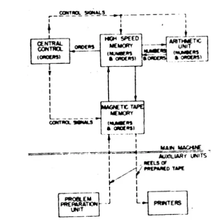
Fig. t is a blockdi~gram showing- tilt' princip.t1 COIl1-ponents of a larg£>-sca}e digit,d computeT. The .lrilhme-tic unit is the only true computing unit in the marhine. That is, it is the only ont' capahle of g-{·[h.··ratin~ flt'W
numbers. The internal (or hiKh-spt'ed I llIemory IS ;l
~_ ~T~ ~~~ - - f -- - - 1
I I I
+ I I
_-1_~
•f
SPEED r---..1_~0I'0£1tS
M£~
----1 ARI ...~
..~.NIT.
TI.t- (M.I~1tS ~ (~1tS
L--~_....J • QlUItSI e e_ ~..!..
storage place for numbers and commands. l)uril1~ com-putation, num~rs which serve .l~ opt·rands an' tr.IIlS-ferred from the internal memory to the aritilllH'til' unit, where the arithmetic operations take place. The result of each arithmetic operation is returnC'd to thcillternal memory. The central control unit of the l1lachine gov-erns the exchange of numhers bdwl'en the illh'rnal memory and the arithmetic unit. Central control gov-erns this exchange in accordance with orders or COI11-mands which are also located in the itltt·rnal memory-For each arithmetic operation, the centrall"ontrol must select two operands from the internal memory, and must supply th£>sc to the arithmetic unit. It must designate to the arithmetic unit which operation (e.g" addition, division) is to bt' pt~rformed, .1ud must transfer tht' res,ult of the operation to a selected memory po,-;ition. Central
I,oft.
194.\' B '(st and /)f Turk: Digit'l' Com pUler for Sdentifit,,- A ppli((ltions 1453
control then initiates the next operation by selecting from the internal memory the next command.
The magnetic memory units are ust'd to supplt·ment the internal memory. Thesc units s.tPre Ilumt>t.'rs and
orders on magnt't ic Lqw. The ~pc~d of opc'ra t ion of the
magnetic units is considt'rctbly less than that of the
in-ternal memory, hut the storage capacity is many times
greater. The~ units also st.-rve as input-output devices
for the computer.
The page printers and probkm-pn:paration Ilnit shown in Fig. 1 are auxiliary units which are not directly connected to the main part of the machine, but which communicate with the computer by means of the mag-netic memory units. The problem-preparation unit
con-sists of a manually operated keyboard which is u~d to
record initial numbers and commands on magnetic tapt'.
This device makes use of additional magnetic stora~e
containing the commands for frequently lIsed
comput-ing routint's. Thus, certciin complete routines may be
introdulI..'d into the computer hy a single manual
op-, eration. The page printers are electrically operated tyP(~
writers \\ hich respond to signals reconh·d on magnetic tarw. They are used to record the final results of com-pu ta t ion.
Becau~' one command is r~quired for each arithl~l'tic
operation, it might seem that a prohibiti\'e numbt.'r of
comIlland~ would have to be introduced irho the ma-chine in ordt'r to direct the solution of a relatively simple problem. This is not the case. The jter(ltivt' methods of numerical analysis involve the repeated performance of computing routines_ \Vhen a routine is rerwated, the commands governinli{ the computation may ditTer from those of tht' pn'\"illlJs cycll' only with respect to some
systema tic pat tl'rn of v;lria t i,m. By storin~ commands in
the internal memory and by the lise of ~llitable schemes
for their coding, they may lX' introduced into the
arith-metic unit and modified by addition or suhtraction. As
,111 example of the et1ectin·ne:-.s of this process, the total
number of commands which must be supplied to the machine to obtain all of the roots of a polynomi;li equa-tion should not exceed fiftpen_ This numher is in(.it:pend-ent of the degree of the polynomial.
The complexity of the problems which a Illadline
can solH' etliciently is limited hoth hy computation
..;peed and memory capacity. For exampll" p.lrtial
difTt'r-\'ntial equations in three dimt'n~ions ;tnd time m.1Y
require a total storage of 108 numbers alld llIay ir1\olvl'
1010 arithmetic operations. In the preSt'nt machine. the
internal memory has a capacity of approximately -lOOO numbers, ann the JX'rmanent storage nH'dium associated with each magnetic memory unit has a capacity of 200,000 numbers. The oyer-all speed of tht' computer depends primarily upon the time required to pt.'rfornl the basic arithmetic operations and the time required to select a number from the internal lllt·tnor\,. In this machine, 900 arithnH·tic o(J(;'rations together with the lssociated memory s('\('ctions are {X·rfonned each iecond.
Since the entire function of the machine is to rarry
out nUflwrical computation in accordance with C,~if·d
commclI1<.is, the representations of nllml)(:r~ ;Ind I
(lJll-mands are oa:-:ic elements of the machillt.' dl'~iC:JJ ~
urn-bt-'rs may bt: rt:pn:~('nted in a \'ariety of way!". dt'[)t>mlin..:
upon both the mathematical and the phY51cal TlH',II) .. em ployed_
:\fatht'J11atical repreS('llt:1tions m;l~' t:;mpl,;\- ditf"!I'I:"t nUIlliwr bast'~,;. Thus an n-digit d('( ilTl:11 nlJmh~'r (ba~ ..
ten). as c()nn'l1tionally written. i"':1 shorthand ('xpres-sion for the quantity.
where the integer ('I)dlicients Aj :1re tIl(' di~its of thl'
number. :\ny Aj in thl' dl·,iIT1.11 ~\' .. tt'Jll m;lY takt· on ;l yalue frolll 0 through <>. \"llt'n a ntllll/x'r j, rt'presentt'd to the base X, it i-; :-.till \\Tittt'n ,I" ;t seqllence of digit'" A;. but these !lOW are interprl'tt-d .1"
IIll-aJJing-and any digit AJ can now" take 011 nnly the valllf's Ii
through X - l_
In addition to the d('cimal I\ot.ltion, lhi..; palwr ~tll
refer to the Linary sl'.dc of Ilotalil lll; i,t" . X = 2 ill (2
above. Ilere the ollly possible digits .He (I .1I1d 1. TIlt'
hinary equivalents of the dn:iJllalllllllltwr .... 0 through L=i
are shOWJl in Tahle I.
·TABI.E I
[>1-:11''''1. HI,\"R\' /-:1,11'1\ \1.1 " h
I )"cilll:d Hlll.lf) I h"I 111l.d H,Il.HY
() OOO() ~ 1000
1 noo!
.,
lOOt2 0010 10 1010
" 0011 11 lOll
-1 0100 1 ~ lIon
5 OIOt u 1101
6 01 to 14 1110
'i 0111 1 ~. 1 ! 11
The physical representation of a num"b('r to the hast·
X fl'quires a physical representation for ('aeh of the
possible digits (0 through X -1) in each of tht' n·di~it
columns. That i~, each numht>r i:; (it-noted bv a
partinl-lar selectioll from X" physical statl's. For a givl'll
llum-ber base, sen-ral physical repn'sen tat ion" :In' pnssiblt'. depending upon the Illllllht.·r of tc'mporal and spat ial selections used to de ... ign.1te the 1l1l1ll~Jl'r. Fi~. 2 sllo\"
two ways ill which the binary Illlmber IOltO} may L,'
represented. At (a) ttl\' nllTllill'r is iwing tr.ln .. lllittc·d st'ri.t1ly Oil a :-.ingle wire <llld tilt· rcprl.':->t·IH,ltillll is
eTl-tirely temporal. .\t (b) tilt' Illlllll)t'r is Iwing transJ1Iittt·d in panlkl on :-.ix win's ;llld tltt· n·pn- .. t·IILllioll j~
l'lltin'h-spati.ll. III either l'.lSt.', the di:.:it 1 i ... rt·prt.'~t·/Ited by tb.·
prt-'<;encc .of a pIl1..;t·, and tht- digit () by tltt' .lh:-.t·nn: IIf :1 pulse.
Bf'C;lu .. e tht' rult's of arithnwtir are simpkr in the
binary noLltion than ~naTlY uther oase, this notation i~
14~4 PROCEEDINGS OF TIlE I.R.F..
used in the present machine. Binary-decimal conversion is required at the input and output of the machine.
T,"[
(a I
I~-
o~-;---~
+-
I~_-~L
':
I
U---~--~
TIM(o I 2
(b)
Fi~. 2 - St.·rial and pdrallcl n'pn'st'nl<tl itln uf I ht· nllml)tOr 101101. (.l' St-rial transmi~i()n on onto win'. (h) Parallel transmi~ ... ion on ... ix Wln-S.
This may ht· justified in a cakulator for scientific
proh-It.:ms ht'CtluS<.' of the larg-c amounts of calculation that .lr(' doue with comparatively few initial data.
\Vhen ciiS<'ussing machine operation. it is con\'('nit'nt
to speak of a c()mpo~itt' pulse group of fixed length as a
"word." :\ word in the present machine contains 4S
pulse positions or binary digits which are transmitted hetwt'en units in a serial manner. Two kinds of words
arc shown in Fig. 3. These are: (1) a "numl)('r word,"
, ' " N'"'~
I nt .. ,
1\ ..
~"'."".La-~""J."""""-~""~""':'.l~ .. lillJ."""""';'._' ... __ .... .;.l. .. _.;..u. .. ~.J..LLi~...u.... ... u~l-.l.t...-. V'Il'7J.::''' '-- ,., P, &Gt - _ _ • ----J
... 'it~
~-_ _ ~ ••• ~ ... ~~~Wil..U.U!.u..
- -,'... -.. ... .1. ... - _ ~.. .J
~!I~ ~S~'tIf5' \t~;:-~: ... ~ '"':'=~~~. ~,:/. ~ ~~C:
.... i4If"~IICTII(JIII.
Fi~. J' -.\\Iocation of information in nUOll)t'r and ordrr .·ot'll ....
which contains the ahsoillte value of a nu.mht·r. i ts si~ n.
and auxiliary digits used in ch€'cking: and (2) a Mcom ·
mand word." which contains coded pulse groups ca-pabk of governing the machine operation.
The machine cyrle is the basic unit of computing op-t'ration, and in this machine is approximately 1 milli·
second in durat ion. Durin~ this cycle four ciistinct events
take plan'. (1) Two operands art' 8ele<:tcd from the
in-tt'rnal memory and are St'nt to the arithmcti,' "Unit. (2)
The arithmetic unit performs the dt'sired operation.
(3) The result of the op<·ration is sent back to the
in-ternal I11t'mory. (4) The command which gOVl>rns the
next operation is selected from the memory~
A command is required for each machin~ cycle and
contains all the information nect'ssary (or the perform-ance of the cycle, namely, th{' locations of the operands,
the specification of the o~rati()n, the location which is
to receive the result, anci the location of the next
com-mand. Locations within the I11t'mory are ternwd ad·
drl's. ... ·s. and are specified hv hinary numl)('rs which
identify consecut :\Tly all of the storagt· positions of the memory. Oper,ltiofls are also specified hy coded puIs.' groups.
Besides addition, subtraction. dc, S('\Oeral noniuith·
metie ()peration~ are required during tht· "olution of
most problems. The transfer operation st'rv('s to transfer a word lwtwtlcn di tTt'ren t memory lOLl t ions, or hetw .... ell
tht' internal nWOlory and on(' of the ma~l1t'tic mel1lon
units. The sub=,titllti()T1 operation i~ lISt'd to rnodih' ;l
COJl1tl1.lf1d word hy addinK or stlhtracting from nn(' Ilr
mort· of tht, .lddrt'ss(·~ contained within tht, command
The hranch OptTa t ion aHow:-; t h(' mal hill(' to chopst·
ht'tw{'en two computing rOtltint·s c)11 rht· h.l .. i~ of tht' ft··
suits of past computation. The \omm.lllcl .~n\Tlllill~
the hranch operation ('ontain=, tht' IO\'atiolls of two com·
mands, only one of which i~ to 1)(' chosen to KOVl'rn the
next c()mputin~ ("yc~{'. Thi:'i choin' i~ ddl'rmint,d hy tll«'
sig-n of tht' inequality of tht' tW() IIpt'r.tnds . .'\s an ('X;Ull·
pit-of the use of the.: branch OPt'f.lt.jllll. considt'r tiw ~1I111'
tion of a polynnmi tl \'qll;ltioll. :\n .lpproximatt' root of
the eqllation j:, c'lkllhted hy I1Wall...; of cOIllHuting rllll· tint· .\. The ditT"rence betwt>t'n thi:-\ apprO,illl.ltion and the last appr(W;'11.1tion is ohtaint'd. If this ditTt'renct> i ..
RTf'aft'r than <;I·n1(' prl'.1ssiglwd tlundwr. th .. next
com-mand selected '" tht., first comcom-mand of rllut;lw :\, and it ...
S(·\t·( tiflll results in the caleuLltion (If a rll'.Ht"f ;lpproxi
mation. If the rlifferf'Tlce is less th.lIl th.· pn'.e...;tahli.;.hl'd
tolerance. th(' nt'"t command 'W·II'\ ft·d ,~ the Initial
("omrn;lnd of rOIl'in#' B, which inifi:ltf'''' n·dlh tion of tht,
dt"~n·t· of the l,.,h·n ·mia1 in prep,Hatton for tht· calcuL,·
tion of the next root
III. I:-OTERs."L \tE\lOkY
The int('rnal l1lf'mory must he capahlt' of st()rlTl~ .1
laq{e numht'r of \\ortis with ~h()rt a("ce!'~ timt~. Thc
ston'd illfortnatinfl must be {'a~ih- t"ra~ible. In the
prt'S('nt mat h;'"1(, tlH' internal mt.'mOf\ m,lkt·s 1I~ of the
;lc(,lJ~tic ,'pIa\, "nc p. tht' ~t'lT.l~t· nu'! h.\I\I",n. Fi~. "
r~: -~~
..
c-. ,-..
_d.
I
_
....
-is a bl()('k dia~ram lIf an acollstic delay linf' in which
mercury is the acoustic medium. Assume that the lin('
contain~ some pul~ configuration at a givcn instant of time,· and th3t tht' configuration is propagatinR down the line at the velocity of sound in mercury. Each puts.'
rt"ceived at the output transducer is ampliflt~d and
194,\ West arid DeTurk: Di,ilal Comput~' for Snerlufir. Applicalwrst
applied to a gate or reshapt·r \10 hieh allows a ne ... {liglt
pulse from a (Ol1llnuous pul<;(- ~urn' to he fed 10 the Input trall!l(IUt"('r. Thus, the pul-.c t:onfiguration Will cir
-• ul,ltc ;W.JIIIHI Ihl' elm,l'oI Ino,1' uH .. ktil1ildv \I. ithoul I ,ruf,:H'!»>i \l' tlq.:~.'nl·r,\ til/II uf I h,· 11111 ... , .. ha!JC.!> o~ the Ilul..c
·ll.It me
'11w 1I111111"'r ,,( )1111 ... · p, ... it;olll> \I. hI< h a 11I1~' CHILI.lllh
1.\' .• II~ ~1'lr"1o(t" , .lp.1t 11\ 1<; propOrtitlll;11 tn the 11I1W
.Il·I;I\· of Ih,' 11110" ,IIlU the fr"ql/"ney (If the ("ont;nuou ...
"ul!.l.· !'onune The former i:-I;lIliled L, till" ;1llenll.IIIo.11
"f lilt" 1I1t:nury and th .... tr'ln~lut'l'rs; the JaU("r. 11\' th,
' •• Hld" irll h \10 hi, h can be all ai !ll'U .trOU lid till' • In IItlf
i,,"
p,l(h and the <lcpenrlcIH:e of attcnuation on fn'quon, y
TIll' au'l's.., time of the dcl.i\ lint' i ... equ:lI tl1 the dd.L\
lillII'. For a gln'n memory ,·.II',lfi!)", the ~u.:("e~", tl1lW 111.1\'
ht: 11,'\ rc.l~.:d hy dCl'rc;'l .. ;ng the 1""I1~th of l':ll h hilt' :111<1
,rwrt";l~lnj.: Iht' 1.11 .. iI I1Unillt"rllf hll.· .. \\hdl' the rept'lil1vn
1';1\.' i~ h.·klrollstant kt'duC""liol1 ohta;o\·t! in this 1ll.lIllla ... rO .. lh. hlr Ih,· tlltal 111"IHOrv t'quipmcnt is rrin\,lr;l~ 1""purtl"rI,11 In tilt" nllllll,...·r of cirnllol!LUI1 )I •• tlls ,\lid i
:-'l1h .... ·".Il.t.lril~ Il1nUt'lltl'd h\ the .J1I1·I1I\,lti"l1 per p.ilh
I he .It 0 , ... ~ lillie call Ix reduced mure t:lrr"lively by HI·
rl·.J~III;" !lIt' )lulse-rt.1)clition r.Jte and shortening tht,
tile. \I./IIIl' hulding COIIst.Ult the llull1llo;'f of lines anti the
Tlul .... · j ;1I).1£"it~ of ,',II
n
Tltl' 1".· ... ·nllll.1l hl1l' tll'SI!>:1l 111.Ikl·~ ":.t.' of 255 .JlUll',I;...:
kld\ lin. ~ .,1\ h • .JIM"'C IIf :.olnring 16 infurlll.Jlioli \\orJ",
I1ld 0111' .t-i.t'llt,II.J1 \I.'/nl u:.cd flOr t IWI:"in"" Thl' lul.1I
IIl'mUr) 1.II>.Iuty h, IhudurI·. -t1)1:IO \l.urJ ... The ddol~
'Ill'!'> "1",r,I(" at ,I jlUI .... ··h·I".:lilillu I.lll" IIf 1 \k, o:wd the
ti~it pub.es art: dmplLtudt'·lIll.uul.l\l·d upon .1 .10· \ It.:
.Irr..-r Thl, IIIl'lII"n .1' \ t· .. ., \Il11i' I" .1I"'lIt .HIO 1111, ru
-t" ond ...
Fi~. 5 i:. a 1,1, .. I. (Ii.l).:rdlll uf oJ. IldoJ.Y line sho\l. ing !Ill' ''""l' uf .. Jdllion,11 !>:.lln fur rl'"dlll),: li I' .. t"king ;n(nrlll.l
-1011 f,um Ih\· hll'·} ... rHIIH( lLI·., ]lUllIU).: iuforlll..lll'H1
III" thi' "lit·}, .1I1t! <,·r,l:-ill).: IIII' l·r ... "'C f,:.ilt! .lIul Ihe \\II'e
""'''J'
.
_--~.
'
-'~'
....
.
""",..
-
.
-::
:
,' r
I
-'
'-
-,.,
'.
"""
,"\1
~
.
.
,
- (O"·l"""
"
.
...
..
..
that tht: dela)' lime bc a constanl int~r;;:ral multiple of
the r)l . .'riod of the (""ontinllou'l pul~ ",uurce use' I (or r,' -.. h..lpin~. 1'," ,ILl"'"
ttw
.1rnu'Iti, \,t'IOI it\ in Illl'rt ury "1t'lllpo:·r;Hur,··~I'·JI(·udt'nt. loOmc 1I1t',11lS of t('lIIpt'r.ltur~
, 1""0111 rnl j ... rt·.pllr,·". Tnl' t "111 pcr., I un' , """ ffi,'i"nt of .\nlll"
,i,'
\,t'lu,."IIY , .. "Ill Ii th.11 .1 I p • ."r ,,'nl ('han'l:t' in rid",llillt' H~lIh .. fr"Ill " h'IllII('r,llurl' .h.111e'· of m~(- Th.·
',·ml"·r.Jllll.,
,·If.·
,
t 111.1\ I",· '·'I'rt''''""l·.11l1Itr'·PIII\·'·Il1t''III\10\ III<"
"'I'l.Ir,.",
\l.hl"r .... J.I ... th., l ... rf1li~",hlt· 1,·llIllI'r,l\lIr,· \ .ri.III"'1 II!
d"grel'" \"'lIi~r."I.·. \' I~ tit,· l"t.oI nU'l1l1.·r '" 1',,1 ... , p ... ,
',lIn!'> ill thl' lint:, "nd " j., th.· fr,\rli"n "f .1 1'"1 .... · p...r ••• "
hy" hi, II till' dd,IY' ,'11, II.III!.:\· ,Ill.! ... till ,dl,,\\ r.· ... h.1II1.I ..
of tilt" liT' 111.11:11).: 1'1I1 .... ·~ Ih lhin ... h.lrp pul ... · .. il1 Ih. r,
~h,'pil1~ "I"'r,ltl<'l1 tilL' 1.11'11" of 'I !II.'\ III' 1II."k .... 1" .. 1,
,1<; 0 75 \Iith"ut dllll(ult\ III Ih, pro "'lIt ,1t"'I;.:rl. l',I' Ii
,Id..l\' lillt' nllll,III'" 765 \llI).,l· .... 11101 th.· '·"rrl'~I,.·n,l,n ..
III·nlll ... l),lc Il'IIIIlt-I·.lllIr.· ~T.l'hl·nl i" "'I,rU\'I1I.lld\" i I
1'1'1II1"·r.llurl· \(r,ldl,·IlI .. in Ihe 11,,'111"" L.III
I,,·
'''II
Itlllk,l, \\1t,lt' 1'·'\"',/II.II,k 'IjUll'lILl'IIt ... , .... 11.1111\
11\,I;nl.1I11I'1i I,y .,uhdl\·idmg thl' 11I\"IIIL1n 11\1,. ,r,,,,p' ~rl
hnl'" E..II h ~roup nt,l~ o.;oll:oi.,t ,,( .... ·L'·r,d ( ... r, 6 I', In
intlt'I"'lhll'lIl ,I\·uu .. til' l ... th", up. r.lllIIg wllhill oJ. "'11I~'f' ,011l.lIo\·r "f 1II\'rt.un. I'hc rc!.III\c!\· Im~h IIh'rl11.d lOll
dUlli\il\ 1)( !IIl'roun I,.. dTl·IIIL.· 11\ I-..n:plllL..: Ih,' ,:L'
.11,11\:- 1 .. ;t\\lTII Il.Llh .. ,,/11,,11 E.u·h 1"III,l\Ih', , ... th'lI
"'LIppi It'll \I.'lh .111 IIUlqlt;I1t1t:1I1 !t·rlll"·r.llllro ·o '111'
I1Il"1h,lI.i"lII \\hilh 1\1,1111\,1111" III\" 1'·IHI,,·r.lturl· III tho
1". .. ,1 1011"'1,1111
1'1-: h • .,., 1'1I"1I,,;r.,,,h "f l !II1"l. til'"
,tt,.
,I.
UlIl,lIl1nl 1\ a :-1.llnln· .. · .. II"\·j 1,lnl. ).~" 1I\,tll -; 1111 hi" IlIn..;. l~ III' 11t·~hi,L.:h. '11It!!~ lilt II!" \11,10- I hr ... · .1I111/"'IIL ".Ith ... "1"·r.lI,
I.); It l'h"I·""'I'I ... f, III"" .. ,
. " .. !
,,,I,.
..
,~" 'I,n.· " " 1"I~ .,1, """ , I •• , .,~
0' 10·" " ~ ,I" I"'
",lhil1 Ilw I~",I E.i'IL 1,"11 I- 11ILli"l'i, r"Io'[IILI,. I'
1[, .. lrt'lI"rlll.dl~ I'tLiHLI'I[,·d 1"~\·lh,r ... o Ih.1I • " .. ,.1 1" "LII~I~I~ "f thr • ..- Ir.I,.·I~ ·h.· 1.11.;·11 "~I rill '''IIILI!!'
r.t ... ·.1 "111\ 111"'1\ .1 n!"\1 \\" r ,I '" II rillt'n in". I h. II!I"
t''''lIlllLI''U~ Ir. 1I1,.,j"lI 1111 .. tl~h 01 .1 •. 1.,\
I,,,.
rt'qulI.· ...t h •• r·
1111- I"
\\ilh klllJ II'r.1 I lire (Olllnl! '-I~I-,I ' .. ·:;.linLlill
S\l1lhrOlli/,I-ri,'ll 1lt'1\\\"'n till' clt-I.I\· lin,' _Inri .1 ti\l·d-frcqlll'!1C'\· pIll..;(·
I \ -. \ Id I II \1\ TIC 1':,\ IT
-I ht' h\ .. il... <Hithllit'lic 1l1wr,lttun i~ addition. Other ,lritltTlll'tic OllcLltilllb. tllUu.:.h (1ltkd a:-; sillgle
opCrtl-lilIth, arl' compouTlded ()f :-;Lw('t· .. :-;ive additions
per-f',nncd ullder the 1(1(,t! cOlltrol of the arithmetic unit.
\(lllrtlil1~ly. tIlt' lll\dl;llli~1l1 (If additioll Iargl'I~'
dl'tl'r-Illilll':-; the 11l;1I11l('[ ill \\ hich (Ither opt'r;ltioIlS are carried
out. ,\dditioll Illay lit' Pl'rilJrllIl'd :-t'rially or ill pJ.rallel. In a :-'t.Tial ;tddt.·r the t\\l) opn,lnd:-, art.: adJed olli.' digit
;11 a tiTtl(" (C1rl1llll'llcing with tht' 100n·st-()rd(\("~ligit. III
d par,tllcl ,Hider, all of tht' digits of OIlC' Opt.·Lllld art.:
:-illl111tallt.·lIu~ly ad(kd to tth' digit--of the other opt'Llnd,
tll(:n·lf~· gt.'!lCfdtillg ,til th ... , digits Ilf tilt.' slim at ollce.
RE<iSTER C
Fig. 7 is a block diagram illdicatin~ the operation of
;1 ~rial adder. The t wo ()pt.·r:1lld~ art' assumed to be in
rt'gi~tt'rs A and B which may he delay lines. The
S.lIC-('essiYt~ digits of the operands enter the adder, which
generatt.'~ the di~it~ of the sum and enters these into
rcgistl'r A, I n III ul tiplication, the multiplicand stands in
reRister B and the r11ultiplier in register C, The partial
slims generated during multiplication are stored in
ft.·gis-ter A. The serial adder requires a minimum of
equip-mcnt. Its chief disad\'antage is that the time for addition
cannot be less than the circulation time of an oper~l.!ld
in its register. The multiplication time is th(~n equal to
the product of the addition time and the I\umber of
digits used. .
Fig.
at
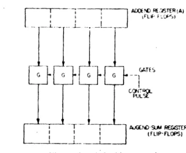
is a block diagram of a parallel adder. Theaddend stands in regi~ter A and the augend in register
B. Upon application of a control pulse, all columns of
the addend arc simultaneously added to the augend and the sum is left standing in the sum-aug{'nd register. In principle, the addition is completed in one pulse time, although practical considerations generally require that
the process take from 5 to 10 pulse times.
Speed is obtained at the expen~ of equipment in the
,It·; I.R.J~. J)uembtr
p.ir.tlkl adder, for the basic columnar adding drcuit must be rqwated for each digit column of the add('nd
and augend. :\ furth('r advantage of the paralld O\,\?I'
the serial adder is that the paralld unit requires 11.· ... 5
cOlllplex control circuits to perform operations
corp-pounded (If rq)(:ated additions.
: ] AIX:i~ RFI3TfR(A)
I \'LIf' f~~1
_L_..-Fig. 8-I',tralld·addt·r 0p('r.ltil)l1.
\\'ith t>ither t~·pc of adder sl'\'eral variations are po~~i hie, dt'pending upon thl' ,'!ethod us(·d to transfer C.lr' ries from one column to another. For ('xamplC', a paralld
adder may first pcrform tlw addit ion wi thou t carries
and later add the carries to the rt'~lllt. The :tddition of
carries may gerwrate new carries which must be added
in again. Such sequenti:tl adding of carries increases tht'
time required for an addition. Simultaneolls additioll
of carrit·s may be rwrformed by adding all carries to th ..
augend in one operation. In this case, the addition spet.·d
is limiteo only by the propa~ati()n times of the carry
plllSt·s and the add pulses through t h(' nt'Ct.·s~:1ry cin·uits.
Before discussing the adder circuits in detail, it i!-'
worth whil(· to describe a shift re~i..;ter. This is a ~implt-r
d('vice than the parallel adder, but invoh'cs similar It'ch
niquC's. The register may be used to convert lX'tWt't'll
S('rial and parallel numlx'r rt.'presC'nLltioll. to changt.' th.· repetition rate of a serially transmitted nllmhef, and til
act as huffer storagt' f()r numocrs t'ntt.'rin~ the .trithnlt'ti,
unit.
The register consists of a chain of flip-flop--, 1)(11' fl.r each digit to he stored, as shown in .Fig. 9, Ol1t' pl.ltt· 01
each flip-flop is connt'cted to the grid of an adjaCt'll!
flip-flop through an electrical delay l1et work. PrC)\'i~i()JI
is made for applying a re~t:t pulse ~illll1ltallt'(llI:--ly to ;111 flip-flops in the register.
If any configuration of ones and zeros stands in tit.
register and a n'set pulse is applied to all flip-tlops, tho:-o,
which stand at 1 undergo a change of state. This changl
produces a pulse at one of the plates which is momentar ily stored in the deldy network associated with that plate. After the rt.:set pulse has passed, cvery pul=-'l'
which entered a delay network cmergC's and tri~gers tho
flip-flop immediately to the right of it. In this 1l1.lIlI1U
the configuration of ones and zeros is ~hifted one columli
to the righ t.
In Fig. " a t:hrct.'-digit word ie shoo wn Stji<l.',l"IY cnl.t:,.'rillb
Ii"lSI (111'1 DeTurk: Di~ital Computer for S(ient~fi( Appliflltion.\
t he shift register. A train of reset pulses is applied to the
"hift register at the same repetition rate as the digits of the entering word. The reset pulses must be advanced, ~"ith respect to the applied digit pulses, to avoid inter-ference between the two pul8C trains. Once the word
~
~;
1
-1 I --1
~
p
"p'
FLoPI
:~~.
n opi.P!
G G
L
G - ~G~
I
L - . _ _ _ _ ._~-Istands in the register it may be read out in parallt·1 from
the plates of the flip-flops, or it may be read out serially at some other repetition rate by applying reset pulses of the desired frequency. Fig. 10 is a circuit diagram of two c()lumns of a shift register which operate rt>Iiably at pulse rates up to 2 !\fc.
L
---- -,
t·.
~, ..
,.0I
r -1 ~
..
0.·
d~~.;. ,,~. ]W. :.,
..
. i
7 • .. - .-~ -.
_
. .-I
...
~I. _ i " . I'·: ;
Fi~. I ()'-Shift-rt"gi!<teor column.
:0 __
The present ma{'hine m~kes use of a parallel adder
with simultaneou!I (arrv, as shown in Fig. 11. In this
circuit the addition (" it hout earn:) of the addend to
the augend occurs fi~t. and il' fnllnwerl by the
simul-taneous addition of all carrie!>. TtM- operands are
as-sumed to stand in the addend (A) and the augend-sum
(B) registers. An add control pulse is applied to the
gates Gl. In each column where the addend contains a
1, the control pulse passes through the normally clO!ed
gate Gl and changes the state of the correspoQding
column of the augend-sum register. Following the
addi-tion without carry, a carry pulse is applied to the
nor-mally closed gates GZ. Gates G4 sense the digits standing
in the,A and B registers. In each column where a 1
stands'in the addend register and a zero in the
augend-sum register, gate G4 opens gate G!. The applit'd carry
pulse passes through G2 to an electrical delay network.
as w(·ll as to gate GJ, through the phase inH'rta I.
Gate G3 is opt.·n if a 1 stands in the aUKl'nd-suf11 r<'gistt·r.
-
...
1--"
---
...
-Fi!o:. I1-Parallel adder ('mploying ... imultant>ol/s carry.
and the carry pulse passes GJ to the rwxt higher-order
column, etc. Thus, a carry pulse which is initiated in
any column may pass several gates G3 and be applied
to several higher-order columns. Each time a carry pulae passes a gate GJ, it is applied to the electrical delay net-work associated with the next column. The propagation
of the carry pulst's docs not immcdia tely cause a change
of state in any of the flip-flops, but rath<'r serves to in-troduce the carry pulses into the appropriate electrical
delay networks in accordance with the confi~urations
of the numbers in the A and B regist<'rs. After propaga .. tion of the carry pulse, all pulses applied to the delav
networks emerge and change the states of the associate~J
aug~nd-sum flip-flops. The true sum then stands in the
lower register.
N umbers may be placed in the adder registers by the
use of shift-register techniques, in which rase additional gates and delay circuits are associated with the register flip-flops so that these may function as a shift register during the introduction of a number.
The arithmetic unit of the computer r<'quires nu-merous control circuits in addition to the basic addt·r. These are nect·ssary to perform the compound arithme-tic opt'rations of multiplication and division, as welt as the logical operations described previously.
V. CENTRAL CONTROL
The basic cycle of machine operation requires super-vision of the following processes: selection of the
op-erands from the memory, ~pe(ification of the operation
to be performed. disposition of the result, and the selec"
tion from memory of the next command. :Many possible organiz,ations of the central control unit exist, depending upon the time and manner in which tht> above steps are
carried out. For example: (1) the selection of the two
PROCEEDI.VGS OF lll"~ I.R.E.
operands may occur St'qu~ntially or simultaneously;
(2) the selection of operands may occur while previous operands are being proc{'ssed in the arithmetic unit, or after the arithmetic proc~ss has }wen completed; (3) the disposition of a result mayor may not occur simul-taneously with some of the otht:r steps; (4) part of or all of a command may he selected in one st(P; (5) a com-mand may be selected in accordanct' with information contained in the previous command. or all commands may be located conse(:utivcly in, the memory; (6) the control se-quence may constitute a fix{'d cycle in which each step or combination of steps is allocated a fixed amount of time, or a variable cycle in which each step proceeds as soon ,as the pn'vious step has been com-pleted. There is no knownoptimllm organizational pat-tern for the control'process. Compromises must ~ madt· between speed of operation, simplicity of operation. and
ec~nomy of equipment. By performing a large number
of steps in parallel, the speed, cost, and complexity of the machine are all illcn·ased.
The control system of the pn.·sent machine involves fixed-c\'de, dual-selection operation. Each command is sdected on the basis of informat ion contained wllt-hin the previous command.
:\ command consists of two words w~ich arc stored in adjacent positions in the internal memory. Referring to Fig. 3, it will he seen that each word of a command contains two address positions and a group of checking pulses. The second command word also contains an operation code. For ,most operations, address positions 1 and 2 contain the addresses of the two operands, ad-dress position 3 contains the address of the result, and address position 4 contains the address of the next com-mand. Two exceptions to the above occur: (1) Certain operations (e.g., transfer) require but one operand. This appears in the first position, and the second position is then vacant. (2) In the branch operation the addres&'s of two commands appear in the third and fou~th posi-tions. The branch operation chooses which of the com-mands ,will be used in the next computing cycle.
The fixed-operation cycle is. called the maGhine cycle, and is approximately 1 mi1lisecond in duration. It is compoeed of three equal parts ca11ed major cycles which are equal in duration to the circulation time of a memory delay line, and which are synchronous with the memory circulation. During the first major cycle, the command governing the cycle is selected from the memory, and simultaneously the result of the previous computation is transferred to the memory. The selec-. tions made at this time are governed by the third and
fourth addresses of the previous command. During the second major cycle, thetwo operands speGified by the new command are selected from the memory, and the operation code is transmitted to the arithmetic unit. During the third major cycle, the arithmetic operation occurs.
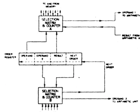
From the above discu&&ion it i. apparent that the cen-tral control unit must contain registers for storing a
com-plete command, and two selection circuits for the simnl taneous selection of two memory locations. -Since
the-operands selected from the memory may arrive at Ct.'n-tral control during any part of the selection cycle, thl' central control should also have one-word storage
f('-gisters for holding the operands until they are to ht·
transmitted to the arithmetic unit. ;\ one-word register for tht.~ re~ult is also required. The simplified
organiza-t ion of the central control is shown in Fig. 12.'
r--~1
. _____ .... _--'1
'tI IIIt'nOlllTIC \IIIIT~---_ 0P'l1WOO'
TO ... _ T I t \101fT
Fil(. 12 -Simplified ofxanization of central contrul.
The operation of central control while making a Riven selection from the internal memory involves a spatial selection of one of 255 delay lines and a temporal selection of one of 16 word positions within tht' line. Tht> address of any memory position is specified by a 12-digit binary number, the lower-order four 12-digits oC which refer to the temporal selt'ction, while the upper-order. eight digits refer to the spatial selection.
A selection of one of 2" gating lines in accordance with an ,,-digit hinary number governing the selection
can be ~ffected through the use of a diode matrix. Fig.
13 shows an elementary matrix in which a two-digit binary number contained in two flip-flops sel~cts one of four gating tubes. The principle of operation depends
[
9
.. I .A,/V'.Ar----t~--~-::::...a~-.--_____r_' .. -:--~
I '
hVVl.~-t::::-o~--+---} ~-L,
-{':i_!~- ~J -~~i'
.£'j~./'.---t-~
i- --
,-
~r·
----fa
&L~_'l~~~
[~~~~b
Fii 13 -Rrctifier matrix.
upon the fact that the impedance across a parallel com-bination of diode gates varies only slightly with the
1948 U'est aM DeT""Je: Dit;ital CD"."""" for Sciextific Applications 1459
number of gatea dOled if at least one gate is dosed, but changes abruptly when all gates are opened. The
recti-~r matrix of Fig. 13 can be extended in both directions
to accommodate as many binary digits as desired.
VI. MAGNETIC
ME)(~RY
The magnetic memory units serve to augment the
internal memory of the computer, to introduce initial data and command. into the machine, and to record the
results of computation. Theae units make use of
mag-netic tape as a permanent continuous-ltorage medium.
Each unit baa a capacity of approximately 200,000
words, and is capable ol operating at a maximum rate
of 500 words per eecond.
Communication between the magnetic-tape units and the other parts of the machine is under the jurisdiction
of the central control. Each unit has assigned to it an
addre. which is of the same form as an internal memory
addresa, except that the address in this cue includes one
of the three operation codes: read, write, and hunt.
The read and write codes are always interpreted as
ap-plyilll to the next cOllleCutive word position on the
magnetic tape. The hunt code caU8e8 the tape unit to hunt for a particular word position, the number of which is supplied by central control.
Becawe ti.e ceatrai.C'OAtrol may call upon a magnetic
melllOl')' uait at ~.
irretular
rates, it i. not feasibleto propel
*
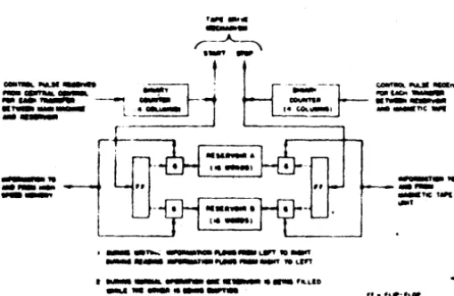
tat- .. rtlIJIPOI* to each individualcom-mand. I_tead, iolOl'mation .. recorded on the tape in blocks of 16 words each and the tape mechanism always operates to read or write an entire block. A mercury-delay-line raervoir Consisting of two 16-war4 delay
lines is a.ociated with each tape unit, as shown in Fig.
14. Durina a .queoce of "'riting operatiolls, the words
,-_.
-r--A....~
...
---
~-
'lli ...
~-
-~---=-=--=-- --:::.
l'
-...
.,.;;;-:..""':.:.- L _- - - I· co._, " ' -r
-~
ILo'
-:=: ..
=-~ l-D~
...
_-_'_'_~
• _ _ _ _ ~_~to _
_ _ _ _ ~ _ _ 1'OL'"
t _ _ _ _ _ _ _ _ "LLID
-..---
, •• fLlllt·'\..,
.-Fie. l+---Or&aniation of mapetic-memory-unit rnervoin.
to be written are accumulated in the consecutive word poaitions of this reservoir. When 16 words have accumu-lated in either delay line, the tape mechanism is actuated by local controls, and the contents of the reservoir are
transferred to the tape. During a sequence of reading
operations, the rnervoir· is filled from the tape, and as
soon as one of the delay lines has been emptied by cen-tral control, the tape starts and refills the delay line.
The recording medium is l-inch-wide magnetic tape
on which five parallel channels are recordt'd. Four of
these contain information, and the fifth serves as a marker or control channel. The marker channel containa markers which identify the beginning and end of each
block of 16 words, as well as binary numbers which co~
secutively identify the blocks.
The maximum speed of operation of the magnetic memory units depends upon the pulse-repetition rate per channel and the time required for starting and stopping the tape. With operation rates of several hundred words
per second, it may be necessary to accelerate the tape
at several thousand inches/sec/sec. Fig. 15 shows the arrangement of a tape-drive mechanism 'which permits
rapid acceleration. A magnetic clutch and drive capstan
is used to propel a short segment of tape which is in
contact with the recording heads. Spring slack absorbers are used to average the motion of the active portion of the tape and to control servomechanisms which drive the take-up reels.
Fig. U--Input-output drive mKhani"m.
VII. CHECDNG
It is desirable that a computer ,bt' self-checkin& in
order·to minimize the number of undetected errors. The error-checking mechanism should be highly diagnostic, so that the location of a defective part is indicated when-ever an error occurs. By incorporating diagnostic check-ing equipment in the design, the trouble shQOtcheck-ing of equipment failures is greatly facilitated and the per cent of the total time during which the machine is operati\'r
is proportionately incre~.
Numerous methods (or checking digital computers have been suggested. Some of these include the simul-taneous operation of duplicate equipments, the repe-ti-tion of each operarepe-ti-tion or its inverse on the same equip-ment, and the use of operational checks which involvr
the periodic running of a test problem. .
Checking by duplication of equipment may be un-desirable for several reasons. The total amount of equip-ment is doubled, thereby doubling the cost as well u the total frequency of failures. Repeating each operation
or
itS
inverse reduces computation speed by one-half.It also teems doubtful that checking acherne. baaed on
fr/~"
..
PROCEEDINGS O'THI!. I.R.E. Decemberthe .repetition of each operation can be made sufficiently
diapoetic to indicate the location oi a failure. The
periodic running of a tHt problem has many of the
dis-advantages cited above concerning 1088 of apeed and
lack of diagnostic informati.on. The existence .of a time lag between an err.or and its detecti.on makes it difficult t.o detetmine the exact point in the c.omputing r.outine at whkh failure occurred, and c.on!equently increases the difficulty .of resuming .operation. It is possible that intermittent errors might escape detection altogether.
It may al90 be difficult or impossible to c.onstruct a test
pr.oblem which completely checks the machine (e.g., tesu all storage positi.ons or all contr.ol circuits).
A genera) system of checking developed by Bloch,. known as the method .of weighted c.ounts, is believed to offer numer.ous advantages in regard to ec.onomy, re-liability, speed, and diagnostic' ability. A ,particular adaptation of this theory is used to check memory storage, word transfers, ,and arithmetic operations in the present machine.
The successive digits of a binary number may be said to be valued .or weighted with the value 2- where" is the number .of the column. The c.onventional value .of
the number is then the sum of the weights of those
c.olumns in which lis appear. A different number can be -obtained by weighting the columns in a different
man-ner. F.or example, successive columns may be given the
weights I, 2, 4, 1, 2, 4, etc. The new number is the sum of the weights off all columns in which the digit 1 occurs. This new number (or rather, the I.owest-order f.our digits .of it) is called the weighted c.ount of the original number. Each number st.ored in the computer has its weighted c.ount stored with it (note the gr.oUP of checking pulses in Fig. 3). A number can be checked whenever desired by formulating a new weighted c.ount and checking this for identity with the weighted count carried with the number. Such a check is perf.ormed each time a number
is transferred fr.om one locatio~ to an.other.
It can be sh.own that the basic arithmetic processes
can be checked by means of the weighted count. Such
checks are possible because the sum (difference, product) of the weighted c.ounts of tW.o numbers has a known rela-ti.on to the weighted count of the sum (difference, prod-uct) .of the numbers.
. The weighted-count system of checking st.orage and transfers is operative thr.oughout the machine. \Vhen initial input data and commands are manually rec.orded in the pr.oblem preparati.on unit, weighted c.ounts are generated simultane.ously with the depressi.on of the re-cording keys. Thencef.orth" each word contains its own weighted count. Each transfer of a word fr.om the time .of manual recording up to and including the time when results are printed by a page printer is cheeked by the weighted-count process.
Additional checking methods are used to verify the selecti.on of memory positi.ons, and the tra'nsfer of .op-eration codes. A selection frQm the mem.ory involves a
temporal selection from among the 16 information word positions in each line and a apatial selection from among, the 255 delay lines. Each delay line has a seventeenth word position which contains the binary number of the line. Whenever a line is selected, the number of the line is taken from this seventeenth word position, and is compared f.or identity with the number of the line as it occurs in the c.ommand g.overning the selecti.on. An additi.onal. delay line is used t.o check temporal seJec-tions. This line operates in synchronism with the 255 information lines. The 16 'inf.ormati.on word positi.ons of the extra line c.ontain the binary numbers fr.om zer.o t.o fifteen. Each time a w.ord is taken from an
informa-ti.on lin~, a w.ord is simultane.ously gated out .of the extra
delay line, and the number so .obtained is compared for identity with the word positi.on as it appears in the c.ommand g.overning the selecti.on. In this way, each selection made fr.om the mem.ory is checked during the 8electi.on cycle in which it occurs.
The transmission of .operation codes fr.om the central control to the arithmetic uf!it is,checked by incorporat-ing a code generator in the latter unit. For each arith-metic operati.on the code generator returns an operation code to central c.ontr.ol for checking purposes.
Although the checking system is elaborate, i'n the sense that each function of the c.omputer is checked during each operating cycle, the equipment necessary t.o provide such checking does n.otexceed 20 per cent of the t.otal equipment in the computer. The checking
equipment has associated ~ith it a set .of c.ontr.ols and
neon lights which operate to st.oP the machine in the event .of an error and to indicate the location of the fault. The actual numbers and commands which were . being processed when the err.or occurred are displayed to the machine operat.or. By virtue of these diagnostic aids, a defective part or subassembly can be quickly located and replaced, in many cases without loss .of in-formati.on .or the disruption of the c.omputing routine.
BIBLIOGRAPHY
'I. R. M. Bloch, R. V. D. Campbell, and ~f. Ellis, '.'Logical Design of the Raytheon Computer," Mathematical Tables & Aida to Com-putation, :-'ational Research Council, Washington, D. c., S4:hedulrd for publication in vol. 3, no. 24, October, 1948, issue.
2. T. K. Sharpiesa, "Design of mercury delay lines," EkarOflia,
vol. 20, pp. 134-138; ~o~mber, 1947. '
3. L. S. Ridenour, .cRadar System Er\iineerini,· McGraw-Hill Book Co .• New York. S. Y .• 1948, pp. 632, 667-671.
4. Computation Laboratory or Harvard University, -Proceedings of a Sympoaium on Larae Scale Digital Calculating Machi~,"
A"Mls of the Computation Laboratory of Harvard Univenity, Harvard University Pre$S. vol. 16. 1946.
5. H. H. Aiken and G. M. Hopper, -The automatic ~uence con-trolled calculator I, II. III," F.l«. E,.,., vol. 65, no.8-II; Auguat-September, 194 7.
6. F. L. Alt, "Bell Telephones Laboratories Computer I, II,"
Mathematical Tables 4: Aida to Computation. National Re3eatch
Council, Washi,..ton, D.
c.,
vol J, no. 21, 22; January and April. 1948.7. A. Goldstine and H. H. Goldstine, -The Electronic Numerical