TE
AM
FL
Y
Wireless IP Networks
Toni Janevski
Library of Congress Cataloging-in-Publication Data
Janevski, Toni.
Traffic analysis and design of wireless IP networks / Toni Janevski. p. cm. — (Artech House mobile communications series) Includes bibliographical references and index.
ISBN 1-58053-331-0 (alk. paper)
1. Wireless communication systems. 2. Telecommunication—Traffic. 3. Mobile communication systems. I. Title II. Series.
TK5103.2.J38 2003
621.382’15—dc21 2003041890
British Library Cataloguing in Publication Data
Janevski, Toni
Traffic analysis and design of wireless IP networks. — (Artech House mobile communications series)
1. Mobile communication systems—Design and construction 2. Wireless Internet 3. Telecommunication—Traffic I. Title
621.3’8456
ISBN 1-58053-331-0
Cover design by Igor Valdman
© 2003 ARTECH HOUSE, INC. 685 Canton Street
Norwood, MA 02062
All rights reserved. Printed and bound in the United States of America. No part of this book may be reproduced or utilized in any form or by any means, electronic or mechanical, including photocopying, recording, or by any information storage and retrieval system, without permission in writing from the publisher.
All terms mentioned in this book that are known to be trademarks or service marks have been appropriately capitalized. Artech House cannot attest to the accuracy of this information. Use of a term in this book should not be regarded as affecting the validity of any trademark or service mark.
International Standard Book Number: 1-58053-331-0 Library of Congress Catalog Card Number: 2003041890
Preface xv
1 Introduction 1
1.1 Evolution Process 1
1.2 Why Wireless IP Networks? 2
1.3 Traffic Issues 4
1.4 Design Issues 5
2 Third Generation Wireless Mobile Communications
and Beyond 9
2.1 Introduction 9
2.2 Evolution of Wireless Communication 11
2.3 Second Generation Mobile Networks 12
2.3.1 GSM—State of the Art 15
2.4 Evolution from 2G to 3G 16
2.4.1 HSCSD 17
2.4.2 GPRS—Tracing the Way to Mobile Internet 17
2.4.3 EDGE 19
2.5 Third Generation Mobile Networks 20
2.5.1 Standardization 20
2.5.2 UMTS 22
2.5.3 WCDMA 28
2.5.4 TD-CDMA 31
2.5.5 cdma2000 32
2.6 Third Generation Mobile Applications and Services 35
2.6.1 New Killer Applications 38
2.6.2 Real-Time Services 41
2.6.3 Nonreal-Time Services 43
2.7 Future Wireless Communication Networks Beyond 3G 44
2.7.1 All-IP Mobile Network 47
2.8 Discussion 49
References 49
3 Wireless Mobile Internet 53
3.1 Introduction 53
3.2 IP 54
3.2.1 IPv4 54
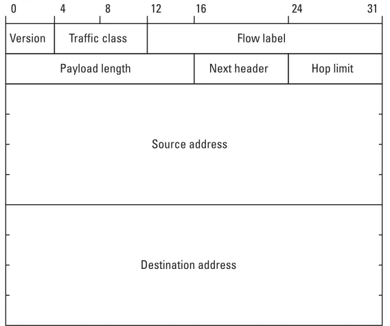
3.2.2 IP Version 6 56
3.3 Transport Control of IP Packets 57
3.3.1 TCP Mechanisms 58
3.3.2 TCP Implementations 61
3.3.3 Stream Control Transmission Protocol 62
3.4 QoS Provisioning in the Internet 63
3.4.1 MPLS 64
3.4.2 Integrated Services 66
3.4.3 Differentiated Services 69
3.5 Introduction of Mobility to the Internet 73
3.5.1 Mobile IP Protocol 74
3.5.2 Micromobility 76
3.6 QoS Specifics of Wireless Networks 83
3.6.1 Cellular Topology 83
3.6.2 Mobility 83
3.6.3 BER in the Wireless Link 85
3.7 Discussion 86
References 87
4 Teletraffic Theory 91
4.1 Introduction 91
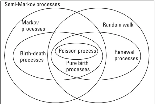
4.2 Some Important Random Processes 92
4.3 Discrete Markov Chains 96
4.4 The Birth-Death Process 100
4.4.1 Stationary System 104
4.4.2 Birth-Death Queuing Systems in Equilibrium 106
4.5 Teletraffic Theory for Loss Systems with
Full Accessibility 106
4.6 Teletraffic Theory for Loss Systems with
Multiple Traffic Types 111
4.6.1 Loss Systems with Integrated Traffic 112
4.6.2 Phase-Type Distributions 114
4.6.3 Multidimensional Erlang Formula 117
4.6.4 Priority Queuing 120
4.6.5 Error Control Impact on Traffic 123
4.7 Teletraffic Modeling of Wireless Networks 126
4.8 Principles of Dimensioning 129
4.9 Discussion 132
References 133
5 Characterization and Classification of IP Traffic 135
5.1 Introduction 135
5.2 Characterization of IP Traffic 136
5.2.1 Aggregate Internet Traffic 136
5.2.2 Internet Traffic Components 137
5.3 QoS Classification of IP Traffic 139
5.4 Statistical Characteristics 143
5.4.1 Nature of IP Traffic 144
5.4.3 Statistical Analysis of Nonreal-Time Traffic 152 5.4.4 Statistical Analysis of Real-Time Services 155
5.4.5 Genesis of IP-Traffic Self-Similarity 158
5.5 Discussion 164
References 164
6 Architecture for Mobile IP Networks with
Multiple Traffic Classes 167
6.1 Introduction 167
6.2 Architecture of Wireless IP Networks with
Integrated Services 168
6.2.1 Network Architecture 169
6.2.2 Integrated Simulation Architecture 170
6.3 Conceptual Model of Network Nodes 171
6.3.1 Scheduling Schemes 173
6.4 Simulation Architecture for Performance Analysis 176
6.5 Wireless Link Model 177
6.6 Traffic Modeling 179
6.6.1 Call-Level Traffic Modeling 179
6.6.2 Packet-Level Traffic Modeling 180
6.7 Mobility Modeling 186
6.7.1 Macromobility Model 187
6.7.2 Micromobility Model 190
6.8 Performance Parameters 190
6.8.1 QoS Parameters on Call-Level 190
6.8.2 QoS Parameters on Packet-Level 192
6.8.3 Capacity 193
6.9 Discussion 195
References 196
7 Analytical Analysis of Multimedia Mobile Networks 199
7.1 Introduction 199
7.2 Analysis of Mobile Networks with Single Traffic Class 200
7.2.1 Analytical Modeling 200
x Traffic Analysis and Design of Wireless IP Networks
TE
AM
FL
Y
7.3 Analysis of Multimedia Mobile Networks with
Deterministic Resource Reservation 204
7.4 Analysis of Multimedia Mobile Networks with
Statistical Local Admission Control 208
7.4.1 Efficiency of the Mobile Network 211
7.4.2 Optimization of Mobile Networks 215
7.5 Traffic Loss Analysis in Multiclass Mobile Networks 217 7.5.1 Application of Multidimensional Erlang-B Formula
in Mobile Networks 217
7.5.2 Multirate Traffic Analysis 220
7.6 Traffic Analysis of CDMA Networks 226
7.6.1 Capacity Analysis of CDMA Network 227
7.6.2 Calculation of the Soft Capacity 233
7.6.3 Numerical Analysis 234
7.7 Discussion 236
References 237
8 Admission Control with QoS Support in
Wireless IP Networks 239
8.1 Introduction 239
8.2 System Model 240
8.3 Hybrid Admission Control 242
8.3.1 Hybrid Admission Control Algorithm 242
8.4 Analytical Frame of HAC 244
8.5 Optimal Thresholds in HAC Algorithm 253
8.6 Analysis of the Admission Control in
Wireless Networks 255
8.7 Admission Control in Wireless CDMA Networks 260
8.7.1 SIR-Based Admission Control 261
8.7.2 Load-Based Admission Control 262
8.7.3 Power-Based Admission Control 263
8.7.4 Power Control 265
8.7.5 Performance Measures for CDMA Systems 265
8.7.7 Hybrid Admission Control Algorithm for
Multiclass CDMA Networks 266
8.8 Discussion 267
References 268
9 Performance Analysis of Cellular IP Networks 271
9.1 Introduction 271
9.2 Service Differentiation in Cellular Packet Networks 272
9.3 Handover in Cellular Networks 274
9.3.1 Handover in Cellular Packet Networks 274
9.3.2 Handover Mechanisms 275
9.3.3 Analysis of Packet Losses at Handover 277
9.4 Network Model 279
9.5 Simulation Analysis in Wireless IP Networks 280
9.5.1 Handover Loss Analysis for CBR Flows 280
9.5.2 Handover Loss Analysis for VBR Flows 284
9.5.3 Handover Loss Analysis for Best-Effort Flows 290 9.5.4 Performance Analysis of Different Traffic Types
Under Location-Dependent Bit Errors 293
9.6 Discussion 295
References 296
10 Handover Agents for QoS Support 299
10.1 Introduction 299
10.2 Handover Agent Algorithm for Wireless IP Networks 300
10.2.1 Who May Initiate a Handover? 300
10.2.2 Handover Types on a Link Layer 301
10.2.3 Handover Agents 302
10.3 Routing in the Wireless Access Network 305
10.4 Location Control and Paging 310
10.5 Discovery of the Crossover Node 312
10.5.1 Crossover Node Discovery for B Flows 312
10.5.2 Crossover Node Discovery for A Flows 313
10.6 Performance Analysis of the Handover Agent Scheme 314
10.7 Discussion 319
References 320
11 QoS Provisioning in Wireless IP Networks
Through Class-Based Queuing 323
11.1 Introduction 323
11.2 Wireless Network and Channel Model 325
11.3 Design of Wireless Scheduling Algorithms 326 11.3.1 Wireline and Wireless Fluid Fair Queuing 326
11.3.2 WFQ Algorithms 328
11.3.3 Service Differentiation Applied to Existing Systems 331
11.4 Wireless Class-Based Flexible Queuing 334
11.4.1 Class Differentiation 334
11.4.2 Scheduling in an Error State 338
11.4.3 Characteristics of WCBFQ 342
11.5 Simulation Analysis 343
11.6 Discussion 347
References 348
12 Conclusions 351
About the Author 355
Wireless networks have penetrated almost a billion subscribers worldwide with first and second generation mobile networks. The main service was voice, and more recently modem-based low-rate data services. Because of the voice-oriented traffic and circuit-switching technology, these networks are dimen-sioned and designed using the traditional traffic theory in telecommunications. Their design is based on high-cost centralized switching and signaling equip-ment and base stations as wireless access points. Another technology dominated the world in the wired local telecommunication networks: IP technology. The
transparency of theInternet Protocol(IP) to different traffic types and low-cost
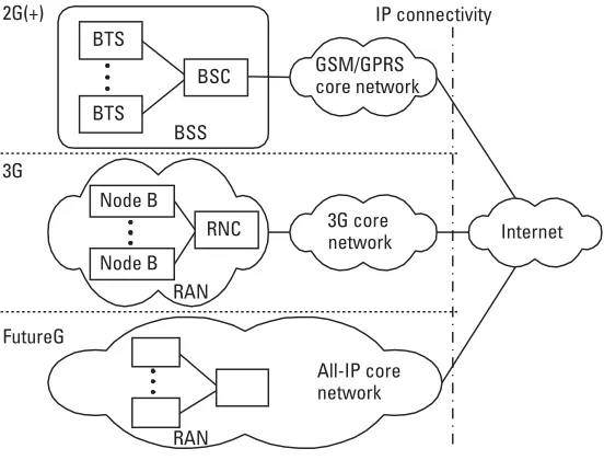
switching equipment made it very attractive to operators and customers. The third generation(3G) of mobile networks introduces wide spectrum and high data rates as well as variety of circuit-switched and packet-based serv-ices. It provides IP connectivity besides the circuit switching. Future generation mobile systems are expected to include heterogeneous access technologies, such as wireless LAN and 3G, as well as end-to-end IP connectivity (i.e., an all-IP network). The diversity of traffic services and access technologies creates new possibilities for both operators and users. On the other hand, it raises new traffic and design issues.
This book provides traffic analysis, dimensioning,quality of service(QoS),
and design aspects for wireless IP networks with multiple traffic classes.
In Chapter 2 we provide a description of existing mobile systems, installed
or standardized, from second generation(2G) towards the 2G+ and 3G mobile
systems.
Internet protocols are the main subject in Chapter 3. We consider IP
pro-tocol version 4 and version 6, as well as the Transport Control Protocol(TCP),
which is the most commonly used protocol on the transport layer in accordance
to OSI. We also describe mechanisms and protocols for introducing mobility and QoS support to the Internet.
Chapter 4 models telecommunications networks and provides the basis of the teletraffic theory (i.e., traffic theory for telecommunications).
Characterization and classification of IP traffic is the main issue in Chap-ter 5. Based on the statistical analysis of traffic traces from real measurements, IP traffic is classified into two main classes, A and B, and several subclasses.
Chapter 6 proposes architectures for wireless IP networks. It also provides traffic and mobility models that can be applied for traffic analysis.
An analytical framework for traffic analysis in mobile networks is given in Chapter 7. We considered single-class and multiclass mobile networks. Analyses
are provided for different access technologies, such as frequency/time division
multiple access(FDMA/TDMA) andcode division multiple access(CDMA). A hybrid admission control algorithm for wireless IP networks is proposed and discussed in Chapter 8. The proposed algorithm considers both call-level and packet-level.
Because of the burstiness of some traffic types (e.g., video traffic) and the random mobility of users, as well as a lack of analytical analysis in a closed form, we perform simulation analysis. Simulation analyses of wireless IP networks under different mobility and traffic parameters in the network are shown in Chapter 9.
Micromobility and location management in wireless IP networks are addressed in Chapter 10. We propose a handover scheme that locates handover management at the base stations by using handover agents.
Chapter 11 discusses scheduling and service differentiation in wireless IP networks. Existing solutions for wireless LANs and 3G networks are considered. Also, we give a design proposal for scheduling in multiclass wireless IP networks based on the traffic classification made in Chapter 5.
The main conclusions from the book are given in Chapter 12.
The material provided in this book is mainly targeted to telecommunica-tions students, members of corporate mobile communicatelecommunica-tions research and development departments, network designers, capacity planners, and anyone who finds the contents of this book helpful.
1
Introduction
1.1 Evolution Process
Cellular mobile networks made unforeseen development in the telecommunica-tions field during the last decade of the twentieth century and the beginning of the twenty-first. Mobile communications are less pragmatic, and continue to demand higher bandwidths and different multimedia services for the end users.
In addition, theInternet Protocol(IP) is technology that started to penetrate the
world in the 1990s, as a result of the development of the World Wide Web
(WWW) and the popularization of electronic mail (e-mail) communication on the Internet. The Web browser was the first widespread application to provide different multimedia services, such as browsing text and images, and streaming audio and video. Technological development in the 1990s and 2000s made computers smaller and smaller, thus allowing users to carry them while moving. The integration of wireless cellular networks and the Internet becomes a fore-seen scenario, one that is being realized from the 3G standardization process and initiatives for future generations mobile networks (e.g., 4G and beyond), as well as from the introduction of mobility to the Internet, which was initially created for hosts attached to interconnected wired local computer networks.
Considering the development of telecommunications technology, one may distinguish among three key events (i.e., revolutions):
1. The introduction of automatic telephone exchange (at the end of the nineteenth century);
2. The digitalization of telecommunications systems from the 1970s to the 1990s;
3. The integration of circuit-switched connection-oriented telecommu-nications and packet-based connectionless Internet in the 1990s and 2000s.
The above path, in the last two steps, was also followed by mobile systems.
Hence,first generation (1G) mobile cellular systems appeared in the 1980s. It
provided only classical analog voice service. Thesecond generation (2G) in the
1990s introduced digitalization of the communication link end-to-end as well as
additional Integrated Services Digital Network (ISDN)-based services and
modem-based data services. Data communication in 2G is provided with data rates of maximum 9,600 bps or 14,400 bps, which depends upon coding redun-dancy. The third generation mobile systems appeared in the 2000s (i.e., the first commercial systems started in 2002 in Japan and South Korea). The global
ini-tiation for standardization of 3G was placed within theInternational
Telecom-munication Union’s(ITU) International Mobile Telephony–2000 (IMT-2000), which was created to coordinate different initiatives for 3G mobile systems from
various developed countries: for example,Universal Mobile Telecommunication
System(UMTS) in Europe and cdma2000 in the Americas. The 3G is created to support Internet connectivity and packet-switched services besides the tradi-tional circuit-switched ones, with data rates ranging from 144 Kbps for fast moving mobiles to 2 Mbps for slow moving mobile users.
Future mobile networks are expected to provide end-to-end IP connec-tivity (i.e., they are expected to be wireless IP networks).
1.2 Why Wireless IP Networks?
The answer is not straightforward, and with each attempt one can include some-thing either for or against them. The circuit-switched wired and wireless net-works (e.g., 2G cellular netnet-works) provide QoS support with appropriate signaling and control information. They are very well defined, robust, and hence very expensive systems. They are created mainly for deterministic voice service, although they can be also used for modem-based data communication. In addition, technological development in the 1990s made computers available for the mass market in developed countries, and the Internet gained momentum in the past 10 years by offering different multimedia content able to be accessed
throughpersonal computers(PCs).
In the telecommunications sector, the basic philosophy is always towards the balance between the costs and the quality (i.e., network operators and service providers tend to provide higher quality of service for lower costs so that end users can buy such services). Hence, it is not only a matter of whether the tech-nology can support some services, but at what costs.
A telecommunications system is composed of two main parts: switching part and transmission part. Switching systems may be exchanges in circuit-switched telecommunications or routers in packet-based networks such as the Internet. Transmission systems are wired or wireless links that interconnect the switching systems. Also, there are links that connect users, fixed and mobile, to the switching systems, which forms the access network.
Then, there are two main costs for the network operators:
1. Equipment and installation costs; 2. Operation and maintenance costs.
For different media types and applications the above costs are lower when all content is carried over a single network than through different specialized networks because of the statistical multiplexing that reduces transmission and switching costs. Accordingly, in the early 1990s European countries began to
developAsynchronous Transfer Mode(ATM) as a technology that would provide
a single network for different traffic types. The idea was to take the concept of “a single socket in the wall” for telecommunication services, similar to an electrical-power distribution network where different appliances can be plug into a same socket. Although well-defined, ATM had high network costs, so it mainly lost the battle with a simpler and cheaper solution. That solution is the Internet Protocol, which is transparent to different multimedia types. Fur-thermore, IP provides simple interconnection and maintenance of IP networks (i.e., local area networks) as well as low-cost switching systems (i.e., IP routers).
Also, together with its main overlaying protocols, TCP andUser Datagram
Pro-tocol(UDP), it provides support for different traffic types. Gaining global popu-larity via the WWW and e-mail, IP emerged as the clear winner over its opponents such as the ATM concept. The Internet provided a new type of econ-omy in telecommunications via support of new multimedia services, as we dis-cuss in Chapter 3.
Definition of a Wireless IP Network. A wireless IP network is an all-IP network with wireless access. All data, signaling, and control information are carried
us-ing IP packets. (Note:This definition is related to this book, and other authors
may use the same term in a different manner.)
1.3 Traffic Issues
The Internet was created to be simple and transparent to different traffic types. But, considering the QoS, Internet basically supports one traffic type for all, which is called best-effort traffic. The creators of IP, however, have left options
for introducing multiple traffic classes via theType of Service(ToS) field in IPv4
header format, and lately via theDifferentiated Services(DS) field in IPv6
head-ers. Integration of IP (i.e., Internet) and telecommunication networks for voice service highlights the QoS support in the Internet like never before. One traffic type for all does not well suit all applications. Also, some users may be willing to pay more for guaranteed QoS. The QoS support is especially important in wire-less IP networks where resources are scarce and should not be wasted.
Dimensioning precedes initial network deployment. After the start of a network, the operator should perform traffic analysis and optimization of the network to maintain given QoS constraints. The design of a circuit-switched network with single traffic class (i.e., voice) is carried in telecommunications by using a traditional approach based on the Erlang-B formula. Traffic distribution and its parameters in wireless networks depend upon user mobility, cell size, bit rate of the wireless link (i.e., cell capacity), network load, scheduling at the base stations (i.e., wireless access points), handover, and location management. A multiclass environment requires network planners and designers to consider dif-ferent traffic parameters for difdif-ferent classes. Hence, packet-based multiclass wireless networks raise new demands on the traffic analysis and network dimensioning.
In a wireless IP network there would simultaneously exist different traffic types, such as voice, audio, video, multimedia, and data. Applications can be classified into real-time (e.g., voice service) and nonreal-time (e.g., e-mail and Web browsing). Different traffic types have different characteristics. For exam-ple, voice service has low correlation and it is predictable. This is not the case with the bursty traffic, such as Web or video traffic. Therefore, one should use statistical analysis to obtain traffic characteristics. Furthermore, different traffic types have different QoS demands. Statistical characteristics and QoS require-ments of different traffic types should be the main parameters for classification of the aggregate IP traffic.
The QoS requirements may be analyzed on different time scales and dif-ferent levels (i.e., call-level and packet-level). However, best-effort traffic should
4 Traffic Analysis and Design of Wireless IP Networks
TE
AM
FL
Y
coexist with higher-class traffic, which has QoS demands. To provide certain quality within the given constraints on the quality measures, wireless IP net-works need an appropriate admission control algorithm that will admit/reject calls depending upon the traffic conditions in the cell and its neighboring cells. So far, most of the admission control algorithms in multiclass networks are based only on a call-level or on a packet-level. But in heterogeneous IP networks one may find as the most appropriate solution to use hybrid admission control algorithms that consider call-level parameters (e.g., call blocking probabilities) and packet-level parameters (e.g., packet loss, delay). Also, different traffic types have different traffic parameters (e.g., bandwidth requirements, call rate, and so forth), which requires an analytical framework for dimensioning and optimiza-tion of multiclass wireless networks. In some cases where an analytical approach is not tractable, one should proceed with simulation analysis of traffic scenarios.
1.4 Design Issues
Wireless networks have their own characteristics. The two most important dif-ferences between the wired and wireless networks are mobility of the users and location-dependent bit errors on the wireless link. These specifics create signifi-cantly different conditions for QoS support.
Considering the QoS support for the Internet, there are several concepts proposed, analyzed, and implemented. First, chronologically, is the concept of Integrated Services, which is based on the end-to-end reservation of resources. To provide unified QoS support for different protocols, such as IP and ATM,
which were developed independently, theMultiprotocol Label Switching(MPLS)
concept was introduced. Finally, there is a Differentiated Services concept, which specifies by definition per-hop-behaviors instead of end-to-end services. This mechanism differentiates the aggregate traffic per class, and hence is scal-able. All of these mechanisms are created for wired IP networks. But, integration of mobile networks and the Internet is a foreseen process. Therefore, QoS mechanisms are mapped from wired to wireless access networks.
Mobile Internet is already present via existing wireless LANs and 3G mobile networks. However, wireless LAN is based purely on the Internet princi-ple in wired local networks, supporting best-effort class only. On the other hand, 3G mobile systems are a combination of circuit-switching and packet-switching technology. Simplified, 3G gets all the features of 2G systems and adds IP accessibility, as well as larger bandwidth than 2G cellular networks, but smaller than wireless LANs. In the future, mobile systems are expected to include heterogeneous access networks.
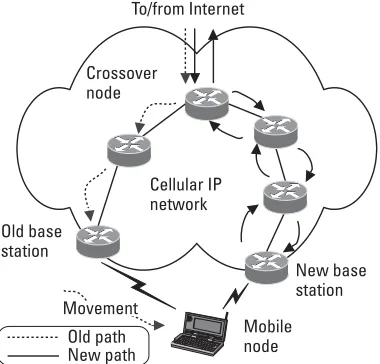
In such a situation an important issue at the network design level is micro-mobility management. Mobile IP protocol is defined as a standard for macro-mobility management (i.e., global macro-mobility), but it is not efficient for local mobility. Several different solutions are proposed for micromobility manage-ment in IP-based wireless networks, such as Cellular IP, HAWAII, and others. There are several important design issues within the micromobility concept, including handover scheme, routing algorithm, and location control. Handover is a process of transiting an ongoing connection from one service area (i.e., cell) to another, and hence, it influences the flow and the ongoing traffic in the net-work. Therefore, one of the main goals of the design of wireless networks is a fast and transparent handover mechanism. It is closely related to the routing in the wireless access network and to the location control, both functions that should be adapted to the IP environment.
The second important characteristic of wireless networks is bit error ratio in the wireless channels (a definition of the wireless channel is given below). In
circuit-switched cellular networks, mobile hosts measure the bit error ratio
(BER) and signal strengths and send periodic reports to the base stations. Using the BER and signal strengths in the wireless channel, a centralized controller of the wireless access points decides whether to initiate a handover or not. Errors in the wireless channels influence the QoS of the affected flow(s). In wireless IP networks we have flows with variable data rate and different QoS requirements. Hence, service differentiation with appropriate scheduling of IP packets onto the wireless link is a challenging problem.
By default, wired routers on the Internet today use thefirst-come first-serve
(FCFS) scheduling discipline. But this mechanism does not offer QoS support. Therefore, we should implement a more advanced scheduling discipline to pro-vide service and flow differentiation. While scheduling in wired IP networks has reached its maturity, it is not the case with the wireless networks. Due to error-prone wireless channels, one should propose different or adapted scheduling mechanisms for wireless networks. There are also different proposals for design
of scheduling mechanisms in wireless IP networks, such as Idealized Wireless
Fair Queuing (IWFQ),Channel-condition Independent Fair Queuing (CIF-Q), andWireless Fair Service(WFS). The design issue to consider is the provision of efficient service differentiation in a multiclass wireless IP network.
Definition of a Wireless Channel. A wireless channel is the amount of band-width that is allocated to a mobile user at a given time. The bandband-width alloca-tion may be provided as frequency band(s), time slot(s), access code(s), or their combination(s). It does not mean that cell capacity is divided into
circuit-switched channels. (Note: This definition is related to this book, and other
authors may use the same term in a different manner.)
2
Third Generation Wireless Mobile
Communications and Beyond
2.1 Introduction
At the beginning of the twenty-first century, we are facing very fast development and deployment of two communication technologies: mobile networks and Internet.
Wireless communications had remarkable development in the last decade of the twentieth century. Figure 2.1 shows the exponential increase in the number of mobile subscribers in recent years. This growth was made possible due to the high-tech development of communication tools, which are no longer only voice-oriented as they were in the past. There are many nonvoice services that network providers offer to users. So, the paradigm of communication any-where, anytime has become realistic. Today, telephony is still the primary serv-ice type in mobile networks, although low bit rate data servserv-ices are also being supported. The lower prices, however, of laptop computers, palm devices, pagers, communicators, and personal organizers are increasing the requirements for multimedia services in mobile systems.
At the same time, Internet technology has been developing as fast as wire-less networks. From the beginning of the Internet (formerly known as ARPANET), the number of users and host computers attached to the Internet doubled each year. Figure 2.2 shows the exponential growth of the Internet (for more details and precise numbers, a reader may refer to [1]). The spreading of the Internet throughout the world is hastened by the invention of the World Wide Web in 1993, which supports user-friendly browsing and retrieval of dif-ferent types of information [2]. Total Internet traffic, however, increases faster
than the number of hosts. The Internet is global and supports a variety of multi-media services. Hence, the Internet is becoming an integrated part of society and culture: in the science world, as well as in the community, entertainment, news-papers, administration, governments, interactive TV, and many more. No one can determine the boundaries of the Internet, if there are any. Of course, the development of the Internet became possible due to development of low-cost
10 Traffic Analysis and Design of Wireless IP Networks
0 200 400 600 800 1000
1992 1994 1996 1998 2000 2002
Number
of
users
(millions)
Figure 2.1 Growth of mobile users (a sketch).
0 20 40 60 80 100 120 140 160 180
1992 1994 1996 1998 2000 2002
Number
of
hosts
(millions)
personal computers and data networks for interconnection of individual PCs for exchanging data and sharing resources. As a technology, the Internet is based on the IP, which is robust enough and transparent enough to support transmission of different type of information (audio, video, data, and multimedia) by using IP packets. We refer to IP and TCPs in more detail in Chapter 3.
The fast development of these two technologies, wireless mobile commu-nication and the Internet, goes towards their integration. Mobile network operators now seek new services to offer to users besides the voice service, because the mobile telephony market is almost saturated in the developed world (almost everyone has a mobile phone). On the other hand, Internet users are seeking connection to the Internet when they are on the move. In most of the cases, people are users of mobile networks and the Internet at the same time. Naturally, the users and the providers have interest in integrating these two technologies. So, although mobile networks and the Internet started sepa-rately—the first generations of mobile cellular systems (first and second genera-tion) were created mainly for telephony service, while Internet was created for global exchange of data and communication between wired (fixed) hosts offer-ing the same service level to all users—the development of these technologies leads toward their integration in mobile Internet or wireless IP networks. We notice this trend in the standardization processes of the third generation of mobile networks and beyond [3–7], as well as in mobility proposals for Internet technology [8–10].
2.2 Evolution of Wireless Communication
The early origins of wireless communication date back to 1861, when J.M.C. Maxwell at King’s College in London proposed a mathematic theory of electro-magnetic waves. Later, this theory was practically demonstrated by H. Hertz in 1887 at the University of Karlsruhe. Several years later, Guglielmo Marconi (at age 21) built and demonstrated the first real wireless communication device in summer of 1895 at the University of Bologna. It was the first radiotelegraph. Officially, it marks the start of the era of wireless communications.
The civilian use of wireless technology began with the 2-MHz land mobile radiotelephone system developed in 1921 by the Detroit Police Department for police car dispatch. Soon, the advantages of mobile communication were realized, but its wider use was limited due to a lack of channels in the low fre-quency band that was used at that time. Hence, higher frequencies were used.
Armstrong made key progress in 1933 with the invention offrequency
modula-tion(FM), which made possible high-quality two-way communication.
smaller service areas called cells, and using same subsets of radio channels in dif-ferent cells. This cellular concept started in Bell Laboratories in 1947, by D. H. Ring.
With the invention of the cellular networks, the next problem that was faced was that of handover (or handoff, which we treat as a synonym for hando-ver) between the cells. It should be transparent to the users. Seamless handover was successfully implemented by AT&T in 1970 in their analog cellular system, Advanced Mobile Phone Service (AMPS), which was placed in the 800-MHz band. The first commercial AMPS service did not begin until 1983.
In Europe, the first mobile systems started in the Scandinavian countries, in order to cope with their sparsely distributed population. The first such mobile system in Scandinavia started in 1978, but the real boom happened with
analogNordic Mobile Telephony(NMT) mobile system, which started in 1981.
There are two versions of NMT: NMT 450 operating on the 450-MHz band, and NMT 900 operating on the 900-MHz band [11]. These systems marked the start of the first-generation mobile systems. Parallel to the NMT, the United
Kingdom developed their Total Access Communication System (TACS), while
Germany developed C-system, which was more advanced than NMT or AMPS systems due to its digital signalization and advanced power control in mobiles and base stations. Japan implemented a modified version of the British TACS
mobile system, called Japanese TACS (JTACS). All the systems mentioned
belong to the first generation. The basic characteristics for this generation include analog transmission of information and incompatibility of the systems in different countries.
Thus, each developed country in Europe developed its own system and standards for it, but different systems were incompatible with each other. This, of course, was less than ideal, since it limited the movement of the users and seg-mented the market for mobile equipment. European countries collectively real-ized this problem and decided to create a pan-European public land mobile
system. Therefore, in 1982 the Conference of European Posts and Telegraphs
(CEPT) formed a study group calledGroupe Speciale Mobile (GSM) for that
purpose. Later, in 1989 the standardization of GSM was transferred to the
Euro-pean Telecommunication Standards Institute(ETSI). Phase-I standards for GSM were published in 1990.
2.3 Second Generation Mobile Networks
The second generation of mobile systems (2G) was under way at the beginning of the 1990s. The first trials with GSM began in 1991, which changed its name for market reasons to Global System for Mobile communications. Soon, GSM overtook the wireless market, having around 700 million subscribers and more than 400 GSM operators by April 2002 [12]. These figures include
GSM 900, GSM 1800, and GSM 1900 mobile systems (we refer to GSM later in this chapter).
Applying the ISDN concept in the design of the GSM, it became a fully digital system. The main characteristic of GSM, besides the digital subscriber line, is roaming. With the introduction of roaming, GSM allows subscribers of one GSM network to use services in other GSM networks worldwide. These characteristics of GSM made it the world leader in 2G mobile systems consider-ing the number of subscribers and network operators.
GSM technology is a combination of frequency division multiple access
(FDMA) andtime division multiple access(TDMA). GSM 900 systems were the
first digital ones. They use the 900-MHz band. For each direction, uplink and downlink, 25 MHz of frequency spectrum was allocated. FDMA is used to divide the available 25 MHz of bandwidth into 124 carrier frequencies of 200 kHz each. Each frequency is then divided into eight time slots by using the TDMA technique (Figure 2.3). Two-way communication is made possible by assigning the same time slots on carriers 45 MHz apart from each other. Each
pair of carriers is called theabsolute radio frequency channel number(ARFCN).
For example, ARFCN=1 uses 890.2 MHz in uplink and 935.2 MHz in down-link, while ARFCN=124 uses 915 MHz in uplink and 960 MHz in downlink direction. Uplink frequency spectrum is in the 890- to 915-MHz band (890.0 MHz is used as a guard channel), while downlink frequency spectrum is in the 935- to 960-MHz band (935.0 is also a guard channel). Each cell has one or more frequency carriers. A couple of time slots on one of the carriers in each cell are dedicated to signaling, while all others are used to carry traffic. In one logical channel several logical channels may be multiplexed. For example, usually 10 different logical signaling channels are multiplexed on two time slots in each cell.
Today, the GSM system operates in the 900-MHz and 1,800-MHz bands throughout the world, due to capacity demands, with the exception of the Americas where they operate in the 1,900-MHz band, due to frequency spec-trum regulations.
TS1 TS2 TS3 TS4 TS5 TS6 TS7 TS8 Frame duration = 4.6155 ms
3 57 bits of data 1 26 bits 1 3 8.25 TS = Time slot
57 bits of data
Parallel to GSM, Japan developed similar TDMA-based technology called Personal Digital Communications (PDC). In North America Digital AMPS (D-AMPS) was launched, a successor to the analog AMPS. The upgrade of AMPS to D-AMPS is made by introducing three time slots per frequency carrier in AMPS, which are separated by 30 kHz. D-AMPS is known as the IS-54 stan-dard, and it is also based on TDMA. Later, this system transited to IS-136, where IS-54 was improved by adding better performances and new services,
such asShort Message Service(SMS). These two TDMA systems, D-AMPS and
PDC, have been deployed worldwide and share the rest of the market, which is several times smaller than the GSM market share in 2G.
Very quickly, the capacity needs of 2G cellular mobile systems increased, and new approaches to cellular technology were needed. In 1993, the United
States approved a new standard IS-95, proposed by Qualcomm, named code
division multiple access(CDMA). IS-95 uses 1.25-MHz bandwidth that can be simultaneously used by many subscribers. The CDMA technique spreads the narrowband signal into wideband signal and assigns a unique code to each tele-phone or data call (we refer to CDMA technology in more detail in Section 2.5). It allows the use of the same frequency bands in the adjacent cells, simplifying the planning of the cellular network.
The roots of CDMA are in military communications, several decades ago. It was very popular due to its robustness to signal jamming. Because the signal occupies larger bandwidth, CDMA is known as spread spectrum tech-nique. Each signal is spread over the whole dedicated bandwidth. In the receiver, the signal is extracted from the wideband signal by correlating it with the user code, which is unique for each traffic stream. In the downlink, the base station uses orthogonal spreading codes to communicate with multiple users using the same bandwidth. The mobile receives the signal by correlating the wideband signal with the known user code. In CDMA, multipath propagation of the signal (due to reflection of buildings, trees, and so forth) is found to be useful, due to diversity gain (i.e., accumulating signal power from different paths gives better signal-to-noise ratio). So-called RAKE receivers collect the energy from different paths. In the uplink direction each mobile spreads the sig-nal using the user code. The base station extracts sigsig-nals from individual con-nections by correlating the wideband signal with the user codes. To be able to perform multiple receptions simultaneously, it is important to have power con-trol in the radio network, so each signal from mobiles arrives at the base station at the same power level.
The primary service in all 2G mobile systems is telephony. However, sev-eral data services are also supported, such as low data rate modem connections (up to 9,600 bps), fax, SMS, as well as supplementary services such as calling line identification presentation, call forwarding, conference call, call barring, and closed user group.
14 Traffic Analysis and Design of Wireless IP Networks
TE
AM
FL
Y
In the following section we give an architectural view of the GSM mobile systems.
2.3.1 GSM—State of the Art
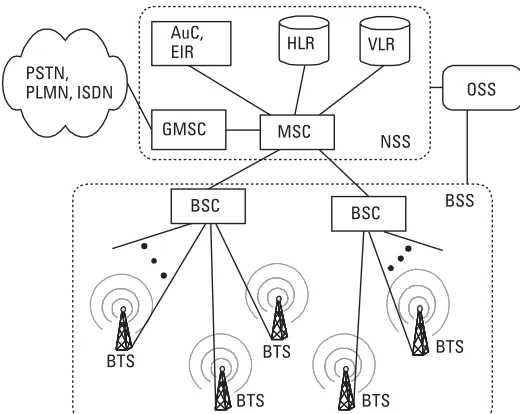
The GSM system consists of the following subsystems: base station subsystem
(BSS),network and switching subsystem(NSS), andoperation and support
subsys-tem(OSS), as shown in Figure 2.4.
BSS consists ofbase transceiver stations(BTSs) and thebase station
control-ler(BSC) [13]. The role of the BSS is to provide transmission paths between the
mobiles and the NSS. The BTS is the radio access point, which has one or more transceivers. Each transceiver operates on one ARFCN at a given moment. The BSC monitors and controls several base stations (the number of BTSs under the control of a single BSC depends on the manufacturer, and it can be up to several hundreds of stations). The main functions of the BSC are cell management, control of a BTS, and exchange functions. The hardware of the BSC can be
located on the same site with themobile switching center(MSC), or at its own
stand-alone site (e.g., in a case of several BSCs connected to a single MSC). NSS includes switching and location management functions. It consists of
the MSC, databases for location management [home location register(HLR) and
visitor location register(VLR)], thegateway MSC(GMSC), as well as the authen-tication center(AuC) andequipment identity register(EIR) [13]. GMSC provides
PSTN, PLMN, ISDN
HLR
MSC AuC,
EIR
GMSC
BSC BSC
VLR
BTS
BTS BTS
BTS BTS
BSS NSS
OSS
interface between the mobile network andPublic Switched Telephone Network (PSTN). MSC is a complete exchange with switching and signaling capabilities. It is capable of routing the calls from the BTS and BSC to mobile users in the same network (again via BSC and BTS) or to users in the PSTN (via GMSC) or to answering machines integrated within the MSC. Physically, MSC and GMSC may be integrated into one network element.
The HLR stores the identity and user data of all subscribers belonging to the mobile operator, no matter if they are currently located in the network or abroad (i.e., roaming). This data is permanent, such as the unique implicit
number International Mobile Subscriber Identity (IMSI), explicit user’s phone
number the so-calledmobile station ISDN(MS-ISDN) number, which is
differ-ent than IMSI, the authdiffer-entication key (necessary to protect the network from fraud), the subscriber’s permitted supplementary services, and some temporal data. The VLR contains the permanent data as found in the HLR of the user’s origin network, of all subscribers currently residing in its MSC serving area. Temporary data slightly differs from that of HLR. Thus, VLR contains data of its own subscribers of the network that are in its service area, as well as that of roamers from other GSM networks. Also, VLR tracks the users considering their residing location area. On the user’s side, permanent and temporal user data is
stored onsubscriber identification module(SIM) cards, which are placed in the
mobile phone.
The AuC is related to HLR and contains sets of parameters needed for authentication procedures for the mobile stations. EIR is an optional database
that is supposed to contain the uniqueInternational Mobile Equipment Identity
(IMEI), which is a number of the mobile phone equipment. EIR is specified to prevent usage of stolen mobile stations or to bar malfunctioning equipment (e.g., from certain manufacturer).
GSM is a system created mainly for telephony service, but it also supports low data rate modem connections up to 9,600 bps. For support of higher data rates in the radio access network (which are demanded by some multi-media services, such as Internet applications), GSM, on its way towards
the third-generation mobile systems, is extended to theGeneral Packet Radio
Service(GPRS).
2.4 Evolution from 2G to 3G
The explosion of Internet usage has had a tremendous impact on the demand for advanced wireless communication services. However, the effectively rate of 2G mobile systems is too slow for many Internet services. As a result, in a race for higher speeds, GSM and other TDMA-based technologies from 2G devel-oped so-called 2G+ mobile systems. In this group we classify the following
systems:High Speed Circuit Switched Data(HSCSD) and GPRS. One may also
classify in the 2G+ groupEnhanced Data Rates for Digital Evolution (EDGE),
but it is somewhere referred to as 3G technology.
2.4.1 HSCSD
HSCSD is a software upgrade to the GSM networks. No extra hardware is required. In the GSM network, single time slots are allocated to each user for voice or data (via modem) connection. Standard data transfer rate in GSM is 9,600 bps, although by reducing the redundancy in the channel coding it may go up to 14,400 bps. HSCSD gives a single user simultaneous access to multiple channels (time slots), up to four of eight in a single TDMA frame. However, it is more expensive for end users to pay for multiple simultaneously occupied time slots.
Assuming a standard transmission rate of 14.4 Kbps and using four time slots with HSCSD allows a theoretical data rate of 57.6 Kbps. This enables Internet access at the same speed of many dial-up modem (56K) services across the fixed access network with 64-Kbps digital transmission lines. Although HSCSD is easy to be implemented in 2G networks, the drawback is the lack of statistical multiplexing (i.e., four time slots are occupied all the time during the connection). A potential problem in HSCSD is handover, which is complicated unless the same time slots are available end-to-end throughout the duration of the call.
While HSCSD is still circuit-switched technology, GPRS is complemen-tary for communication with other packet-based networks such as the Internet.
2.4.2 GPRS—Tracing the Way to Mobile Internet
The fast growth of the Internet increased the user demands for wireless data services. The data rates in 2G were too slow to support Internet-like services, and also circuit-switched technology is too expensive to be used for bursty traffic (i.e., at the air interface, a complete traffic channel is allocated for a single user for the entire call duration). Hence, packet-switched services were needed to introduce statistical multiplexing (i.e., sharing of a single channels by multiple users). For that purpose GPRS is defined as an upgrade to the GSM system.
Par-allel with GPRS,Cellular Digital Packet Data(CDPD) is a similar upgrade for
AMPS, IS-95, and IS-136 mobile systems. GPRS is the first step towards inte-gration of the Internet and mobile cellular networks.
GPRS is created as a hardware and software upgrade to the existing GSM system. In order to integrate GPRS into existing GSM architecture, two new
network nodes should be added:serving GPRS support node(SGSN) andgateway
GPRS support node (GGSN), as shown in Figure 2.5. SGSN is responsible for the delivery of packets from/to mobile stations within its service area. Its main tasks are mobility management (including location management, attach/ detach), packet routing, logical link management, authentication, and charging functions. GGSN acts as an interface between the GPRS packet network and
external packet-based networks (i.e., Internet). It convertsprotocol data packet
(PDP) addresses from the external packet-based networks to the GSM address of the specified user and vice versa. For each session in GPRS, so-called PDP context is created, which describes the session. It contains the PDP type (e.g., IPv4), the PDP address assigned to the mobile station for that session only, the requested QoS profile, and the address of the GGSN that is the access node to that packet network.
There may exist several SGSNs or GGSNs. All GPRS support nodes are connected via an IP-based GPRS backbone network. In the case of GPRS, HLR stores the user profile, the current SGSN address, and the PDP address(es) (e.g., IP address for communication with Internet) for each user. MSC/VLR is extended with additional functions that allow coordination between GSM circuit-switched services (e.g., telephony) and GPRS packet-switched services.
Due to the variety of packet-switched services, such as real-time multime-dia, WWW, file download, and e-mail, each with different QoS requirements,
18 Traffic Analysis and Design of Wireless IP Networks
PSTN, PLMN, ISDN
HLR
MSC/VLR GMSC
BSC
BTS BTS BTS
SGSN
GGSN GGSN
IP backbone network
Data network Internet
GSM core GPRS core
BSS
BTS
GPRS allows defining QoS profiles using the parameters service precedence, reliability, delay, and throughput [14]. The first parameter is priority of the service. There exist three types of priority: high, normal, and low. Reliability describes transmission characteristics of the GPRS network, such as loss prob-ability, duplication, misinsertion, and corruption of packets. The delay defines average delay and maximum delay in 95% of all transfers. The throughput refers to maximum bit rate and mean bit rate.
For location management GPRS has three possible states: idle, ready, and standby. In idle state, the network does not know the location of the mobile sta-tion and no PDP context is associated with the stasta-tion. When the mobile stasta-tion sends or receives packets, it is in ready state. In this state the network knows which cell the user is in. After being silent for a period of time, MS reaches standby state. For location management in standby state, a GSM location area is
divided in several so-calledrouting areas (RAs). To locate the mobile station in
standby state, the network performs paging in the current routing area. In ready state there is no need for paging, while in idle state the network is paging all BTSs in the current location area of the mobile station.
While GPRS utilizes the same radio access network as GSM does, the third-generation mobile networks have defined different radio interfaces to pro-vide higher bit rate services to users.
2.4.3 EDGE
EDGE was created to provide higher data rates for packet-based services with higher bandwidth demands using the existing 2G mobile networks. It is sup-posed to provide an update to GSM systems as well as to the ANSI-136 TDMA system.
EDGE technology was created to enhance throughput per time slot for both HSCSD and GPRS. It uses a new modulation scheme 8-PSK (phase shift
keying) in addition to theGaussian minimum shift keying(GMSK) modulation
scheme in GSM/GPRS networks, and it enables data rates up to 384 Kbps.
Hence, the EDGE upgrade to a GPRS network is also known as Enhanced
GPRS(EGPRS), while enhancement of HSCSD is called ECSD. In ECSD, the
data rate per time slot will not increase from 64 Kbps due to air interface limita-tions, but the data rate per time slot will triple when using all time slots for sin-gle connection in EGPRS, and the peak throughput will exceed 384 Kbps.
EDGE technology is also used over the D-AMPS systems (i.e., ANSI-136 TDMA-based networks), where it provides data rates over 473 Kbps per 30-kHz carriers. This is referred to as EGPRS-136HS. In this way EDGE offers the possibility of convergence of GSM and ANSI-136 systems.
2.5 Third Generation Mobile Networks
The 3G systems should provide convergence of the existing standards in 2G, such as CDMA, GSM, and TDMA. The main reasons for the standardization of 3G are higher data rates in the air interface via implementation of a wideband technology, and introduction of new packet-based services to the end-users (i.e., Internet connectivity). Because GPRS (or CDPD) and EDGE already intro-duced packet-switched services, 3G is created to provide higher data rates and the possibility for creation of various services over the same network architecture (i.e., separating the service creation from the network operation). The network should be transparent and open to new services created by the service and con-tent providers.
2.5.1 Standardization
The process of standardization of 3G mobile networks has several forms and bodies included with it. First, there are regional standardization bodies, such as ETSI in Europe and ANSI in North America. Furthermore, there are global standardization efforts, such as ITU standards for 3G called International Mobile Telephony 2000 (IMT-2000) as well as the 3G Partnership Project (3GPP) and 3GPP2, which include standardization bodies, industry, and acade-mia members.
2.5.1.1 ITU’s International Mobile Telephony—IMT-2000
ITU made efforts for harmonization and convergence in 3G mobile networks through the envelope of 3G mobile systems. Through a consensus ITU decided how much convergence was needed in 3G. In the mid-1990s, ITU created a framework for 3G mobile systems called IMT-2000. The concept of IMT-2000 includes the following aspects:
• Global, seamless access to mobile systems;
• Compatibility with major 2G systems;
• Convergence between the mobile and fixed network;
• High data rates for wireless communication;
• Circuit-switched and packet-switched data transfers;
• Introduction of multimedia applications.
By itself, IMT-2000 covers both third generation mobile terrestrial and mobile satellite systems.
The radio interface was the most interesting element for global standardi-zation, because that is needed to provide universal access of mobile terminals to
different 3G networks. For the terrestrial radio access network, the choice was
made on wideband CDMA (WCDMA) [6]. Within the framework of
IMT-2000, ITU defines five different terrestrial radio interfaces. They are listed
in Table 2.1 together with associated standards. ETSI’s WCDMA andtime
divi-sion CDMA(TD-CDMA) are foreseen as the main users of the first two modes, respectively, while cdma2000 is foreseen as main user of the third one. The last two are (1) Universal Wireless Communications-136 (UWC-136) developed by the Telecommunication Industry Association (TIA) TR 45.3 subcommittee, which is based on TDMA single-carrier, and (2) Digital Enhanced Cordless Communication (DECT) developed by ETSI, which is based on FDMA/ TDMA technology.
Thus, the main idea behind IMT-2000 is global roaming. Although only 3% of the calls involve intercountry roaming [6], the percentage of revenue is higher as these are expensive calls. In addition, global roaming sells mobile ter-minals around the globe. However, there are different interests for both industry and operators, so it is hard to expect that all 3G cellular systems will be compati-ble. But the number of subscribers within the global roaming cloud is expected to increase (within 2G systems, GSM is the world leader, considering the number of subscribers and network operators).
2.5.1.2 3G Partnership Project for UMTS
The ETSI began development of 3G mobile systems in the mid-1990s. The
standard was named the Universal Mobile Telecommunication System(UMTS),
and it is standardized as European terrestrial 3G system.
ETSI completed different studies on the choice of UMTS radio interface in 1996 and 1997. In June 1998 ETSI decided to select wideband CDMA
(WCDMA) as the standard for theUMTS Terrestrial Radio Access(UTRA) air
interface for frequency division duplex (FDD) operation, and TD-CDMA for
time division duplex(TDD) operation. So, UTRA-FDD and UTRA-TDD were
Table 2.1
Standards for IMT-2000 Interface Operation Adopted by ITU
Mode Standard
created, and at the same time UTRA was submitted to the ITU as the ETSI pro-posal for IMT-2000.
In parallel, similar activities started in different regions of the world for standardization of technology like WCDMA. To ensure compatibility of the equipment as well as global standardization for 3G, the standardization
organi-zations involved in the creation of the3G Partnership Project(3GPP). The
part-ners in 3GPP are ETSI (Europe), ARIB/TTC (Japan), CWTS (China), T1 (United States), and TTA (South Korea) [15]. The original scope of 3GPP was to introduce technical specifications for 3G mobile networks based on the evolved GSM core networks and radio access technologies for both FDD and TDD modes. Additionally, 3GPP was amended to include GSM technical specifications as well as GPRS and EDGE, which evolve from GSM as transi-tion to 3G. For more details on 3GPP, the reader may consult [15].
2.5.1.3 3GPP2 for cdma2000
For comprising American and Asian interests on 3G systems, their standardiza-tion bodies ANSI/TIA/EIA-41 started an initiative for the creastandardiza-tion of 3GPP2, running parallel with 3GPP. It was born from ITU’s initiative for IMT-2000. Although 3GPP started by an ETSI initiative in Europe, there was effort to con-solidate collaboration efforts of all ITU members. In the end, 3GPP2 was cre-ated as a solution for American interests and that of some Asian countries. It includes as partners ARIB/TTC from Japan, TIA from North America, TTA from South Korea, and CWTS from China. The 3GPP2 efforts are based on standardization of cdma2000 for the air interface and an IP-based core network with Internet connectivity.
2.5.2 UMTS
The ETSI candidate for 3G is UMTS. This standardization body has defined the strategy for the third generation mobile systems [5] as follows:
• Core network of UMTS should be compatible with IP;
• Should be compliant with IPv4 as well as IPv6;
• Data rates up to 2 Mbps;
• Global roaming—between UMTS and GSM, and between UMTS and
other systems from the IMT-2000 family;
• Support for mobility of users, terminals, and services.
Thus, the main ideas in UMTS are new services (e.g., multimedia serv-ices), content provision, and global roaming.
2.5.2.1 QoS Concept in UMTS
UMTS is planned to include variety of services, each with different QoS charac-teristics. Hence, four QoS classes are defined for UMTS [16] as follows:
• Conversational class;
• Streaming class;
• Interactive class;
• Background class.
When defining UMTS QoS classes, which are referred to as traffic classes, one should take into account the characteristics of the air interface (i.e., band-width limitations and error characteristics).
The main distinguishing factor between the QoS classes is the requirement for real-time service. In that sense, the parameter that defines real-time traffic is delay. Conversational class is defined for very delay-sensitive traffic, while the most delay-insensitive traffic is background traffic class. The first two classes, conversational and streaming, are specified to carry real-time traffic. The others, interactive and background classes, are mainly defined for nonreal-time applications.
communication). Examples of background applications are e-mail, SMS, down-load of databases, and reception of measurement records. Table 2.2 shows the QoS attributes defined for each traffic class.
To describe the QoS level for a given service, one needs definitions of QoS parameters (or attributes, as noted in [16]). Attributes defined for UMTS are as follows: traffic class (conversational, streaming, interactive, or background), maximum bit rate (Kbps), guaranteed average bit rate (Kbps), delivery order
(yes, or no), maximumservice data unit(SDU) size, residual bit error ratio,SDU
error ratio (SER), transfer delay (ms), traffic handling priority, and some other less important attributes (the reader may go to the ETSI Web site http://www. etsi.org for more details on its recommendations).
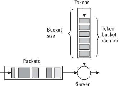
Let us briefly go through QoS attributes in UMTS. Maximum bit rate is the maximum number of bits transmitted over a time interval. The traffic is conformant with this parameter as long as it follows a token bucket algorithm, where token rate is equal to maximum bit rate and bucket size is equal to maxi-mum SDU size parameter. The traffic is conformant with the guaranteed bit rate as long as it follows a token bucket algorithm where token rate equals guar-anteed bit rate and bucket size equals maximum SDU size. The general token bucket algorithm is shown in Figure 2.6. Tokens represent the allowed data vol-ume (e.g., in bytes for IP, or in packets for ATM). They are generated periodi-cally according to the traffic contract and are stored in a token bucket (ATM
terminology), or we may say atoken bucket counter(TBC) is increased by a fixed
value in each small time unit (IETF terminology). If the token bucket is full, arriving tokens are discarded (TBC is equal to the bucket size). If TBC is bigger than the incoming packet length, then the packet arrival is judged complaint
24 Traffic Analysis and Design of Wireless IP Networks
Table 2.2
UMTS QoS Attributes Defined for Each Traffic Class
Traffic Class Conversational Streaming Interactive Background
Maximum bit rate X X X X
Guaranteed bit rate X X
Delivery order X X X X
Maximum SDU size X X X X
Residual bit error ratio X X X X
SDU error ratio X X X X
Transfer delay X X
Traffic handling priority X
TE
AM
FL
Y
(i.e., the traffic is conformant). Otherwise, the packet is marked as noncompli-ant (i.e., the traffic is not conformnoncompli-ant).
The delivery order specifies whether out-of-sequence packets are accept-able or not to the destination. Maximum SDU size is defined for admission con-trol and policing mechanisms (e.g., for policing the admitted bit rate). The residual bit error ratio indicates the undetected bit error ratio, or if no detection of errors is requested, it indicates the bit error ratio for the delivered SDUs. The SER indicates the fraction of SDUs lost or detected as erroneous. It is used in error detection schemes. Transfer delay indicates a maximum delay for the ninety-fifth percentile of the distribution of delay for all delivered SDUs within UMTS network. Traffic handling priority is defined to provide the possibility for differentiation of the traffic within interactive traffic class (it is used for scheduling purposes in the UMTS network nodes).
2.5.2.2 UMTS Architecture
UMTS architecture is described in [17, 18]. According to [17], UMTS’s basic architectural split is between the user equipment (mobile terminals) and the
infrastructure. There are two trivial domains: theuser equipment(UE) domain
and the infrastructure domain. UE is used users to access UMTS services. It includes the identity module and mobile equipment, which may include several functional software groups and hardware devices. The mobile equipment per-forms radio communication with the network and contains applications for the services.
The infrastructure domain is further split in two domains: the network
access(NA) domain and thecore network(CN) domain. The CN domain should have capability to use any NA technique (at least, all global access techniques). The NA domain consists of physical entities (nodes), which manage the radio
Tokens
Token bucket counter Bucket
size
Packets
resources. The CN domain consists of physical entities, which provide support for the features and telecommunication services (e.g., mobility management, call management, and so forth).
The core network consists of thecircuit-switched(CS) domain and
packet-switched (PS) domain, as defined by [17]. These two domains in CN are over-lapping in some common elements. CS mode is the GSM mode of operation, while PS is the mode supported by the GPRS. The entities specific to CS domain are MSC and GMSC. Of course, there are other entities used by the CS domain, but they are shared with the PS domain. Specific entities for the PS domain only are the GGSN and SGSN, which are introduced for the first time
in GPRS (i.e., 2G+). To distinguish between 2G and 3G entities we usually
write 3G-SGSN for SGSN in UMTS, while 2G-SGSN or just SGSN for GPRS, and so on for other domain-specific entities, either for CS or PS domain. The entities common to both domains in the core network, CS and PS, are home subscriber server (HSS), AuC, VLR, EIR, and SMS-support nodes [17]. HSS is master database for a given user, which contains user identification (numbering, addressing information), user security information (authentica-tion, authorization), user location informa(authentica-tion, and user profile information (to which services the user has access). In the previous releases of UMTS, instead of HSS, the HLR was used. From now on, HLR for the CS and HLR for PS domain are considered as subsets of HSS, where HSS additionally provides IP multimedia functionality in the core network. Other common entities have similar functions as previously described in the GSM and GPRS sections in this chapter. The UMTS Network architecture is shown in Figure 2.7.
26 Traffic Analysis and Design of Wireless IP Networks
PSTN, PLMN, ISDN
HLR MSC/
VLR GMSC
SGSN
GGSN
GGSN Other data
network Internet
Core network
PS domain CS domain
External networks RNC
RNC Node B
Node B
Node B
Node B
UTRAN
Considering the access network, two different types are specified for
UMTS: the BSS and the radio network system (RNS). The BSS is the
GSM radio access network solution (also used for GPRS and EDGE). BSS consists of the BSC and BTSs, where each BTS serves one cell. Usu-ally several BTSs are grouped in a base station and placed on a single site. For UTRAN we need network elements responsible for radio resource management, handover management, and power control. This network sys-tem, which corresponds to the GSM BSS, is the RNS, but it significantly
dif-fers from the GSM access operation. RNS consists of the radio network
controller (RNC), which controls the radio access nodes, called Node B. A Node B is a network component that serves one cell. We have different types of Node B, such as macro, micro, and picocells, where we face different requirements in traffic, coverage, and services. There are two types of Node B for UMTS: Node B FDD and Node B TDD. The latter is targeted to hot spots in coverage, while FDD is planned for wider coverage area (micro, macro).
For lowering the costs of 3G system implementation, it is planned to colo-cate BTS/Node B, and BSC/RNC sites. UMTS/GSM colocation ensures greater efficiency by sharing space and infrastructure. An overall comparison of
2G, 2G+, and 3G mobile networks architectures, services, and terminal’s
capa-bilities is given in Table 2.3.
Table 2.3
Comparison of 2G and 3G Mobile Networks
Network
Second Generation (2G)
Second Generation+
(2G+) Third Generation (3G)
Core network MSC/VLR, GMSC, HLR, AuC, EIR
MSC/VLR, GMSC, SGSN, GGSN, HLR, AuC, EIR
3G-MSC/VLR, 3G-GMSC, 3G-SGSN, 3G-GGSN, HLR, AuC, EIR
Radio access network
BSC, BTS, MS BSC, BTS, MS RNC, access node, mobile station
Services Voice, SMS, ISDN supplementary services
Voice, SMS, e-mail, WAP services
Voice, Internet, multimedia services, videotelephony Data rates Up to 9,600 bps (or up to
14,400 bps)
Up to 57.6 Kbps for HSCSD; Up to 115 Kbps for GPRS; Up to 384 Kbps for EDGE
Up to 2 Mbps
Mobile terminals
Voice-only terminals User-friendly terminals, en-hanced service capabilities
2.5.2.3 UMTS Frequency Bands
In 1992, the World Administrative Radio Conference (WARC-92) identified the 1,800 to 2,200-MHz frequency band for IMT-2000 [19]. 3GPP has speci-fied frequency bands for UMTS for both radio access modes, FDD and TDD.
In Europe 12 carrier pairs are available in FDD mode (5 MHz for uplink and 5 MHz for downlink). So, in FDD, duplex connection is realized by using different frequency carriers for uplink and downlink direction. In TDD mode, uplink and downlink are implemented in the same frequency band (same car-rier). It is achieved by defining time frames and time slots. In TDD mode, the network allocates radio resources on a time-slot basis in both uplink and down-link where time slots are grouped into frames. A certain number of time slots within a time frame is allocated to uplink, and the remaining time slots to downlink. So, the transmission occurs quasi-simultaneously. Seven 5-MHz car-riers are available in the TDD mode, as shown in Figure 2.8.
2.5.3 WCDMA
WCDMA is a UTRA-FDD mode of operation. It uses direct sequence CDMA.
The termwidebandis used to differentiate WCDMA from 2G CDMA based on
technology pioneered by Qualcomm, called cdmaOne (or IS-95 CDMA). WCDMA uses approximately three times wider bandwidth than cdmaOne (i.e., it uses bandwidth of approximately 5 MHz per carrier). The same carriers may be reused in neighboring cells. Radio access network separates each user flow (voice, data, and so forth) by multiplying the user information with pseudo-random bits called chips. The chip rate specified for WCDMA is 3.84 Mcps (millions of chips per second).
2.5.3.1 CDMA Operation
In CDMA operation the narrowband signal of the user is spread across the whole bandwidth of the carrier, which is much wider. For this reason, CDMA
technology is sometimes referred to as spread spectrum. An example of the
spreading of the user signal is shown in Figure 2.9.
28 Traffic Analysis and Design of Wireless IP Networks
UMTS TDD
UMTS FDD uplink
UMTS TDD
UMTS FDD downlink
1,900