TeleVideo@ ..
TS
806/20 Computer System ....
Installation
and User's Guide
d~
.---:_
..."
TeleVideo@
TS
806/20 Computer System
Installation and User's Guide
TeleVideo Document No. 2226500 October 1982
Copyright (c) 1982 by TeleVideo Systems, Inc. All rights reserved. No part of this publication may be reproduced, transmitted, transcribed, stored in a retrieval system, or translated into any language or computer language. in any form or by any means, electronic, mechanical, magnetic, optical, chemical, manual, or otherwise, without the prior written permission of TeleVideo Systems, Inc., 1170 Morse Avenue, Sunnyvale, California 94086.
Disclaimer
TeleVideo Systerl1s, Inc. makes no representations or warranties with respect to this manual. Further, TeleVideo Systems, Inc. reserves the right to make changes in the specifications of the product described within this manual at any time without notice and without obligation of TeleVideo Systems, Inc. to notify any person of such revision or changes.
"Warning: This equipment generates, uses, and can radiate radio frequency energy, and if not installed and used in accordance with the instruction manual may cause interference to radio communications. As temporarily per-mitted by regulation, it has not been tested for compliance with the limits for Class A computing devices pursuant to Subpart J of Part 15 of FCC Rules, which are designed to provide reasonable protection against such interfer-ence. Operation of this equipment in a residential area is likely to cause interference, in which case the user at his expense will be required to correct the interference."
TeleVideo® is a registered trademark of TeleVideo Systems, Inc. Z80A® is a registered trademark of ZILOG Corporation.
CP/M® is a registered trademark of Digital Research, Inc. RM/COBOL ™ is a tradefXIar~ .of Ryan-McFarland Corp. MmmOST™ is a trademark of TeleVideo Systems, Inc.
TeleVideo COBOL TM is a trademark of TeleVideo Systems, Inc. WordStar™ is a trademark of MicroPro International Corporation.
TABLE OF CONTENTS
Page
LIST OF FIGURES ... v
LIST OF TABLES ... vi
1. INTRODUCTION ... 1-1
1 .1 System Description . . . .. 1-1
1 .2 Limited Warranty. . . . .. 1-1
1 .3 Hardware Configuration ... 1-3
1 .4 Software Overview ... . . . .. 1-5
1 .5 Using the Manual ... 1-6
2. SYSTEM INSTALLATION ... 2-1
2.1 Unpacking ... '. . . . .. 2-1
2.2 Software Registration ... 2-3
2.3 Selecting the Right Location ... ' ... 2-3
2.4 Installation ... ~ ... 2-4
2.5 Checklist of Installation Instructions ... 2-10
3. OPERATING THE SERVICE PROCESSOR ... 3-1
3.1 Introduction ... 3-1
3.2 Initial Start Up ... '. . . . .. 3-1
4. OPERATING THE USER STATIONS ... 4-1
4.1 Introduction ... 4-1
4.2 Turning On the User Station .. : ... ' ... 4-1
4.3 Types of Drives in the Multiuser Environment ... 4-1
4.4 Booting the User Station . . . .. 4-3
4.5 Operating Under MmmOST ... 4-3
4.6 Working with MmmOST ... 4-6
5. OPERATIONAL GUIDELINES. . . .. 5-1
5.1 Introduction ... 5-1
5.2 Flopp'y Diskettes ... I • • • • 5-1
5.3 Write-Protecting Diskettes ... .' ... 5-6
5.4 Backing Up the Hard Disk ... ~ . . . 5-7
'5.5 Work Habits ... 5-7
5.6 Summary of Good Practices ... 5-8
6. UTILITY' PROGRAMS ...•... , . , .... , . . . .. 6-1
6.1 Introduction ... 6-1
6.2 Using the Utility Programs . . . .. . . .. 6-1
TABLE OF CONTENTS
Page
7. . r SYSTEM TROUBLESHOOTING AND GENERAL MAINTENANCE ... 7-1
7.1 Care ... 7-1
7.2 Troubleshooting ... ' ... ~ ~ ... ' . . . 7-1
7.3 Changing the Exterior Fuse ... 7-3
7.4· How to Get Service . ~ ~ ... ; ... : ... : . : . . . 7-4
AP'~ENDICES
·:···.··A.
O,<S ..
~·C.
:·0.
E.
F.
G.
H .
INDEX
TS 806/20 Specif,ications ... ;... A-1 Statement· of Limited Warranty ... ; : ; ; . . . B-1 Suggested References ... : .. ; ~ .. ~ ... ~ . . . C-1 Pin Connector Assignments ... ~ .... ~ . . . 0-1 Port Asssignments ... E-1 Buying Additional Diskettes ... F-1 Cable Specifications ... . . . G-1 Using the Time and Date Capability in Applications Programs ... H-1
. . . ... . . . , ... , ... ',' ... ' ... X-1
LIST OF FIGURES
.,' ,.' ~ " .... t· •..or
!~.' "".~ .~.
Page
1-1 . TS 806/20 Computer System ... ' ... ',' ... : ... I •••• : 1-1
1-2 Possible TS 806/20 Configurations ... 1-2
.
'\ -;
", 3
1 -3 Floppy Diskette ...;... .. ;. ::.' . ..
1-1 -4 Diskette Inside Permanent Plastic Enclosure ... ; ... .' ... ' ... .". 1-4
. , " r.(.~r ~.~ .. " t"
2-1 Cable Connector ... '\; 2-5
2-2 Correctly-Folded Excess Ribbon Cable ... : .... 2-6
2-3 Rear Panel of the TS 806/20 ... 2-6
2-4 Location of Screws in the TS 806/20 Case .. ~ : ... ~ . ~ ... ':~'~,~.' .. : ~ ',.' :\~:.: .. ' .:::.~ .... 2-7
2-5 Location of Internal Switch 1 ... ~ ... ~ ~ ~ ~ ... ~ ... ,.: ... ' :,2-7
2-6 Closed and Open Switches ... : .... :.:. ~ .. ~ ... ~ .. ~ . , 'J • ';' ~./; • • • • • • • )2-8
3-1 On/Off Switch on Rear Panel ... ; ... ~ ... ::~.: ... 3-1
3-2 Location of Reset Button ... :". . . . .. 3-2
3-3 Service Processor Terminal System Message ... ;":.~ ...
< . . . ..
3-6~ " : ..
5-1 Opening Floppy Drive Door ... , .. ~ ... ':' . ... . . . .. 5-1
5-2 Removing Diskette From Jacket .... ". '. . . . .. 5-2
5-3 Write-Protecting Diskette ... : . . . .. . . . .. 5-2.
5-4 Holding Diskette Before Insertion ... 5-3
5-5 Inserting Diskette in Floppy Drive ... 5-3
5-6 Diskette Tracks and Sectors ... 5-4
5-7 Diskette and Protective Lining Inside the Protective Black Plastic' Enclosure ... 5-5
5-'8' Write-Protected Diskette ... 5-6
5-9 Typical Back-Up System ... '. . . . .. 5-7
7 -1 Location of Exterior Fuse . . . .. 7-3
7 -2 Good Fuse . . . .. 7-3
7 -3 Burned Out Fuse ... 7-3
7 -4 Location of Serial Number on Rear Panel . . . .. 7-4
G-1 RS232C... . . . G-1
G-2 RS422 ... : ... ~ . . . G-1
LIST OF TABLES
Page
, 1 '.
1 ~ 1 " TS ,806/20 Ports ... ' ... ' .. '. . . . .. 1-5
2~1 Cable Specifications . . . .. 2-5
2~2 .. $witch Settings for RS232 Terminal Port Switch 1 ... 2-8
2-3 , Setting Baud Rate of Termi~al Port on Switch
f ...
2-9' : , ' '
. 3-1 Hardware Error Abbreviations ... 3-6
4-1 :T5 ,~061?O Logical and Physical Drives ... 4-2
4-2· Logical Drive Capacities ... ' ... ' ... ' ... ". . . . .. 4-2
.. 6·' , Utility Prograrns Run From a Service Processor Terminal ... 6-1 :6-2 ',Utility Program Format. . . .. 6-2
,6-3 Utility Programs ... , ... .' ... 6-2
6-4 COPYFILE Error Messages ... 6-6
7 -1 r:roubleshooting Procedures ... 7 -1
0-1 P2 Connector Assignments ... D-1
0-2 P7 Connector Assignments ... 0-1
0-3 P4 Connector Assignments ... D-2
1.
INTRODUCTION
...'...
... ,.,..., , ... ...1. 1 SYSTEM DESCRIPTION
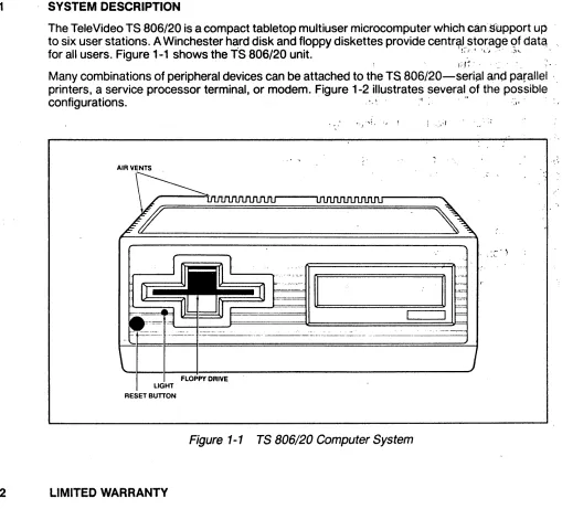
The TeleVideo TS 806/20 is a compact tabletop multiuser microcomputer which can:support up
to six user stations. A Winchester h~rd disk and floppy diskettes provide centr~l,storage 9f data.,
for all users. Figure 1-1 shows the TS 806/20 unit. ! . .' t 'I' ", ,,)'. "
: I,; ,~ , , : ' :,', '
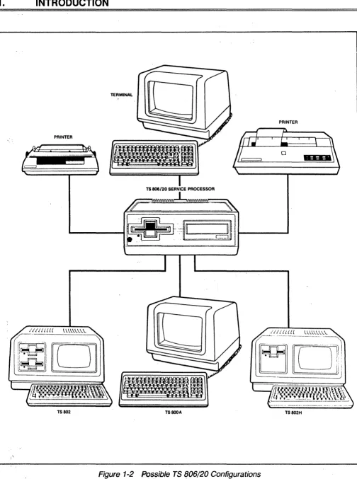
Many combinations of peripheral devices can be attached to the TS 806/20-seri~1 and parallel '
printers, a service processor terminal, or modem. Figure 1-2 illustrates several of the possible '
configurations. . , .( , . " ' : , .
! .. ,·r
AIR VENTS
~ \
.~.
,
, , . \ . .
4>---~--.--- - - -... - .. - - - . - - - . - - - . - -... - .... -... - - - . . . j
FLOPPY DRIVE
RESET BUnON
Figure 1-1 TS 806/20 Computer System
1.2 LIMITED WARRANTY
The TS 806/20 is covered by a limited warranty. The terms and conditions of the complete
limit-ed warranty are providlimit-ed in Appendix ~.
Read the installation instructions completely before turning on your system. Incorrect
installa-tion may void the warranty.
1.
INTRODUCTION
PRINTER
PRINTER
TS 806/20 SERVICE PROCESSOR
TS802 TS800A TS802H
Figure 1-2 Possible TS (J06/20 Configurations
1.
INTRODUCTION
================================================================"
1.3
1.3.1
HARDWARE CONFIGURATION
Hardware Overview
The TS 806/20 is a tabletop computer which contains 'the following components:
One 5 1/4-inch Winchester hard disk drive
One 51/4-inch floppy disk drive
Specification details are given in Appendix A.
The TS 806/20 will be referred to as the service processor.
1.3.2 Disk Drives
The TS 806/20 has one 5 1/4-inch Winchester hard disk drive and one 5 1/4-inch floppy disk , drive.
The floppy disk drive is located on the left side of the computer. (See Figure 1-1 .)
The Winchester disk drive is located immediately to the right of the floppy disk, drive.
1.3.3 Hard Disk and Floppy Diskettes
The hard disk is permanently sealed in an air-tight enclosure and is not accessible to you. It has a capacity of 19.14 megabytes of unformatted disk storag,e (formatted 15.04 megabytes). Data can be stored on this hard disk and accessed by all user stations connected to the TS 806/20.
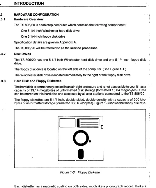
The floppy diskettes are 5 1/4-inch, double-sided, double density with a capacity of 500 kilo-bytes of unformatted storage (formatted 368.6 kilokilo-bytes). Figure 1-3 shows the floppy diskette.
DI
1
o·
I
Figure 1-3 Floppy Diskette
Each diskette has a magnetic coating on both sides, much like a phonograph record. Unlike a phonograph record, it arrives in a protective black plastic cover which is NOT removable.
Lubri-cants inside this cover increase the life of the diskette. The actual diskette can be seen through I
some of the slots in the plastic cover.
1.
INTRODUCTION
Figure 1-4 shows the actual floppy diskette and protective lining inside the plastic cover. When cared for properly (as described in Chapter 5), diskettes can be used many times .
.... 1.- _ ..,..1"\ ""''',../nn ___ ~ .. ____ .... ~I _ _ _ .... "':_II'_"'~_ ... Lo..:_L.. ' _ _ _ ,,_ ... _ _ ... _ _ :,:,,_+: ... ,... ,..; •• " .... i ... !\ "'~l""\n,...,i'V r::
I lit: I \:) OUOI t:.u veil I U\)t: C1lly lIutJtJy UI.,,,t:Ut; ¥Vlllvil 11It;t;"" "llv ;::)t<JvvlllvClUV"~ ~'Yv" '" ~I-'I-''"''''-'''' I •
New diskettes must be formatted before data can be stored on them (as explained in 5.2.2).
Figure 1-4 Diskette Inside Permanent Plastic Enclosure
Applications programs, text, data, and programs which operate the TS 806/20 can be stored on either the hard disk or floppy diskettes.
1.3.4 Peripheral Devices
The ports on the rear of the TS 806/20 allow you to connect a wide variety of peripheral devices.
Up to six user stations can be attached to the TS 806/20. These user stations may (but do not need to) have their own data storage. In addition to the user stations, a service processor termi-nal is used to run utility programs, run service diagnostics, modify the operating parameters of MmmOST, and monitor the operation of the TS 806/20. A user station can also operate as a service processor terminal by changing the switch setting on the rear panel. Refer to the
opera-tor's manual for location and settings of the switch. '
Optional peripheral devices can be shared by all user stations. For hardcopy output, you can connect a serial printer to the port labeled RS232 [OPT]. (This could be a dot matrix, line, or letter-quality printer.) This interface is compatible with most RS232-compatible serial printers currently available on the market, including both character-by-character and buffered printers.
A serial device, such as a modem, can be attached to the RS232 [OPT] port instead of a printer.
You can attach a parallel Centronics-type printer to the port labeled PRINTER.
Refer to Figure 1-2 where several possible configurations are illustrated.
The peripherals described here are al/ in addition to those which may be connected directly to each user station.
1.
INTRODUCTION
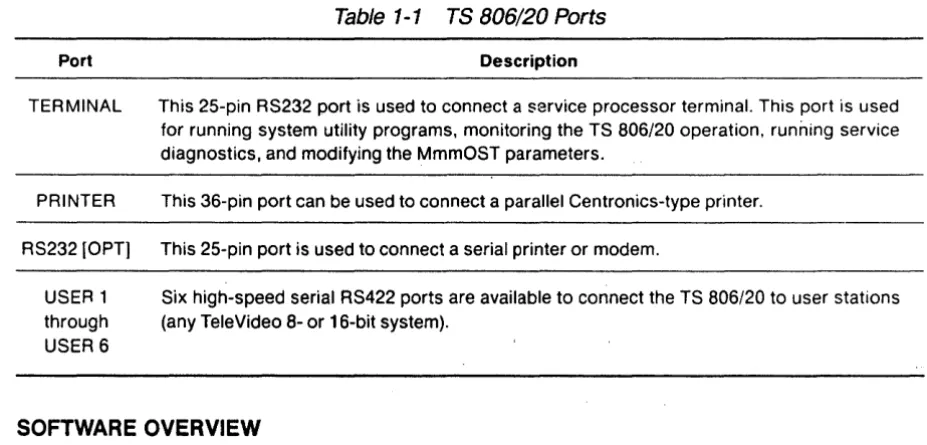
Table 1-1 TS 806/20 Ports
Port Description
TERMINAL This 25-pin RS232 port is used to connect a service processor terminal. This port is used for running system utility programs, monitoring the TS 806/20 operation. running service diagnostics, and modifying the MmmOST parameters.
PRINTER This 36-pin port can be used to connect a parallel Centronics-type printer.
RS232 [OPT] This 25-pin port is used to connect a serial printer or modem.
USER 1 Six high-speed serial RS422 ports are available to connect the TS 806/20 to user stations through (any TeleVideo 8- or 16-bit system).
USER6
1.4 SOFTWARE OVERVIEW
1.4.1 Operating System
Every computer needs instructions in order to operate; these instructions are supplied by a group of programs collectively called the operating system.
When the TS 806/20 is turned on, its operating system is loaded into memory from the hard disk and then into the memory of each user station which is turned on. All TeleVideo computers use CP/M (Control Program for Microcomputers) Operating System software, developed by Digital Research.
If you are not already familiar with CP/M, TeleVideo highly recommends that you refer to the
reference books listed in Appendix
C
and become familiar with the basic operation of the CP/Moperating system.
When the TS 806/20 is used in a multiuser environment, it also uses a special program called MmmOST. MmmOST is an acronym for Multiuser, multiprocessor, multitasking Operating Sys-tem Techno.logy. MmmOST controls access by the user stations to the files and programs stored in the TS 806/20.
1.4.2 Programming Languages
User stations can use any programming language which will run under CP/M. Among these are BASIC, ALGOL, APL, "C," COBOL, CBASIC, FORTH, FORTRAN, MBASIC, PL/I, and RM/ COBOL. When these languages are used with MmmOST, modifications which are described in the MmmOST Programmer's Manual allow them to take advantage of the features of MmmOST. In addition, TeleVideo COBOL allows applications programs to be used with MmmOST with little or no modification.
1.
INTRODUCTION
1.4.3 Applications Programs
Applications programs are commercially available for a wide range of tasks, from accounting to
r-.I"'II." ... i+,. I .... """'''':+i,,, ... ,.".,. ... "" ... , ... :." ... ".. .... "' ... ~ ,.. ... Ii"' ... :""' .... ,.. ... "',.. ... """'...,...,... : ... 1"IiIo. .... , . . ,...,." ... a,...,.. ." .. "..,...,... .... ,...~..-.-: ....
-.;1~"'UI "'1. " I " V V I " I V I . , 1 v U I I 1"1 ... " " 1 v U I V .. ., I I "tJtJ""'''''IVII~ tJl V~I "III~ III V I I " V I " l l v tJl V~I alllllllll~
languages compatible with CP/M~
Applications programs are normally run in the user stations, not in the service processor.
1.5 USING THE MANUAL
This manual will show you how to successfully install and use your new TS 806/20 regardless of your past experience with computers. Every attempt has been made to present all of the infor-mation you will need in a complete and easy-to-understand format. Refer to the operator's man-ual supplied with your user station also.
Your comments about the manual are welcome. To facilitate this, we have provided a Reader Comment Card. Please take a moment to complete and return the card after you have installed your system.
1.5.1 Organization
The manual is organized in the sequence you will need the information. The chapters are as follows:
2 Installation: How to unpack and install the TS 806/20
3 Operating the Service Processor: How to install CP/M and MmmOST and operate the
system'
4 Operating the User Stations: How to operate user stations in a multiuser environment
5 Operational Guidel~nes: How to effectively use the system.and floppy diskettes
6 Utility Programs: How to use the system utility programs
7 Maintenance and Troubleshooting: How to care for the TS 806/20 and what to do if you
have a problem
In the Appendices are the specifications, limited warranty, suggested references, and technical information.
1.5.2 Special Information
Notes will call your attention to information which is of special importance. These categories of notes are used:
General useful information
Important information concerning your safety or possible loss of data.
When you
see this, STOP and read the note before proceeding!
1.5.3 Format of Control Commands
Control commands will be shown as 1\ plus the control character (e.g., I\C).
1.5.4 Carriage Returns
When you should press the RETURN key on the operator's keyboard, the symbol <CR> for CARRIAGE RETURN will be used. (On Televideo terminals, you can press the ENTER key
in-stead of the RETURN key.) .
2.
SYSTEM INSTALLATION
2. 1 UNPACKING
2.1.1 How to Unpack
The TS 806/20 was double-boxed when shipped. Follow the instructions shown here to unpack your system.
The unpacking process will be easier if two people unpack the TS 806/20.
DO NOT USE LONG, SHARP OR POINTED OBJECTS TO OPEN THE INNER BOX AS THEY
MIGHT DAMAGE THE ENCLOSED SYSTEM.
1 . After opening the outer box, lift the inner
box containing the TS 806/20. Gently place on floor.
3.
Gently turn this box on its side.= = = = = = = = , ""=, ======:.:,
2-1
2. Open the box containing the TS 806/20.
There are two plastic foam pieces protecting the system.
4.
Holding the box firmly, gently turn it2.
SYSTEM INSTALLATION
5. TS 806/20 enclosed in two foam pieces.
7.
Remove the top foam piece.6. Turn the TS 806/20 (with foam still in
place) on its side.
8. Lift the TS 806/20 away from the
bottom foam piece and gently place the TS 806/20 on a sturdy, level table.
Save all packing materials and the cartons in case you need to ship the TS 806/20 in the future.
2.1.2 Checklist of Components
As you unpack, check to make sure you received the following items:
1. TS 806/20
2. Envelope containing the following items:
a. TS
806/20
Computer System Installation and User's Guideb. MmmOST Programmer's Manual and software license agreement and card
c. Digital Research CP/M User Manual containing software license agreement and card
d. One floppy diskette containing CP/M (installation only) and one floppy diskette
con-taining MmmOST.
~
SYSTEM INSTALLATION
IF ANY ITEM IS MISSING, CONTACT YOUR DEALER OR DISTRIBUTOR BEFORE PRO-CEEDING WITH THE INSTALLA TION.
~.1.3 Shipping Damage
Check for shipping damage before proceeding with the installation. If the system case appears to be damaged, contact your freight carrier immediately. DO NOT PROCEED WITH THE
IN-ST ALLA TION IF YOU BELIEVE THERE IS ANY SHIPPING DAMAGE. If in doubt, contact your
dealer or distributor as well as the freight carrier.
~.2 SOFTWARE REGISTRATION
Inside the front cover of the CP/M Manual that accompanies the system are the CP/M Software License and License Agreement and inside the MmmOST manual is the MmmOST Software License Agreement. Read the agreements and sign them before opening the package contain-ing the floppy diskettes. Signcontain-ing the agreements and returncontain-ing the cards will:
1 . Entitle you to use the CP/M operating system and the MmmOST operating technology on
your TS 806/20 and make back-up copies for your own use
2.
Register you as a CP/M and M,mmOST Owner, allowing you to receive:a. CP/M User's Newsletter
b. Notices of updates and enhancements to TeleVideo and Digital Research software
c. TeleVideo and Digital Research software bug reports and patches
d. Discounts on updated versions of Digital Research software
TeleVideo will provide you with information regarding MmmOSTand CP/M updates. Do not at-tempt to install any CP/M updates without first contacting TeleVideo.
!.3 SELECTING THE RIGHT LOCATION
!.3.1 Power Requirements
The TS 806/20 requires a steady supply of power:
115 VAC 60 Hertz (domestic) at 1 .0 amps
or
230 VAC 50 Hertz (international) at 0.5 amps
Incorrect or fluctuating line voltages can cause disk error or damage to the system. If you have
any doubt about the line voltages at your location, ask your dealer to check out your facility be-fore proceeding with installation.
= = = = = = = = = = = = . , .. , .... ,'= = = = = = = = = = = = = = = = = = = = = = =
2.
SYSTEM INSTALLATION
2.3.2 Physical Requirements
The TS 806/20 and user stations should be within 300 feet of each other. The service processor terminal should be within 50 feet of the TS 806/20. A serial printer should be within 50 feet of the TS 806/20. The parallel printer (Centronics-type) should be within 10 feet of the TS 806/20. Refer to the printer instructions for recommended distance.
Leave at least four inches of free space around the enclosure for proper air flow. Place the TS 806/20 on a sturdy, flat, level surface. The dimensions are given in the specifications in AppendixA.
2.3.3 General Environment
The TS 806/20 will operate best at temperatures and humidity levels in which you are also com-fortable. Sudden and drastic temperature changes may adversely affect your stored data.
The system requires a clean environment-free of contaminants such as dust, carpet fuzz, and smoke. Excessive moisture or oil particles in the air will hinderthe performance of the system. Keep the system away from the floor where dust or carpet fuzz would be more likely to get into -the floppy disk drive.
2.3.4 Magnetic Isolation
For optimum performance, locate the system at least five feet from other computing equipment, any electrical appliances, or equipment (such as elevators, radio transmitters, and television sets) which generates magnetic fields.
2.4 INSTALLATION
General directions for all installations are given in this section. The next four subsections give directions for connecting the following peripheral devices:
1 . Up to six user stations
2. A service processor terminal
3.· A serial printer or modem
4. 'A parallel Centronics-type printer
2.4.1 Cables
To connect the TS 806/20 to a terminal, user station, printer and any other peripheral device (such as a modem), you will need cables. The quantity and types of cables needed are deter-mined by the number and types of devices to be attached. Your dealer or distributor can supply you with the appropriate cables. The technical specifications for each type of cable are shown in
Table 2-1 . R~fer to Appendix G for more detailed cable specifications.
2.
SYSTEM INSTALLATION
Table
2-1Cable Specifications
Distance in Feet Between TS 806/20 and Peripherals
1 to 20 20 to 100
100 to 300 (maximum)
Type of Cable
Ribbon cable·
24 gauge twisted pair with at least an overall shield
24 gauge twisted pair (individually and overall shielded)
*This is acceptable as long as the ribbon cable is not placed next to electrical devices or cables that could induce electrical interference into the ribbon cable.
Cable connectors commonly have D-shaped end connectors (Figure 2-1). These fit onto a D-shaped pin connector on the rear panel of the system. To install a cable, turn the connector end to fit the pin connector on the device, then gently but firmly push on the connector.
Figure
2-1Cable Connector
As you connect the cables, leave some slack. If you have excess cable left, coil it loosely and secure it with a rubber band. Place the cable out of the way.
If
you are using
a
ribbon cable, .do not rol/ up the excess cable. Rolled ribbon cable looks nice but
it creates an inductor or choke which can adversely affect system performance. Excess ribbon
cable should be folded accordion-style
asshown in Figure 2-2.
2.
SYSTEM INSTALLATION
Figure
2-2Correctly-Folded Excess Ribbon Cable
2.4.2 Power Configuration
The system will be configured for your power requirements at the factory (either 115 or 230 VAC). A three-prong plug is provided. If you use it with an adapter, ground it with a "pigtail." The power cord wires are color-coded as follows:
Green Earth ground
Black Primary power (hot)
White Primary power return (neutral)
2.4.3 Connecting a Service Processor Terminal
To connect a service processor terminal to the TS 806/20, follow these steps:
1 . Attach one end of an RS232 interface cable to the pin connector labeled TERMINAL on the
rear of the TS 806/20. (See Figure 2-3.)
2. Attach the other end of the cable to the RS232 pin connector on the rear of the terminal.
(Refer to the terminal operator's manual if necessary to locate the appropriate connector.)
POWER CORD
-U
FANFigure 2-3 Rear Panel of the TS 806/20
2.
SYSTEM INSTALLATION
The TS 806/20 is shipped with the terminal baud rate preset at 9600 baud. Should you need to change this baud rate, follow these steps:
1. Open the TS 806/20 case'. There are four large screws on the bottom of the case (one in
each corner) as shown in Figure 2-4. Without tilting the TS 806/20, remove the screws with
a Phillips head screwdriver. Once all screws are removed, gently lift off the cover.
Figure
2-4
Location of Screws in the TS 806/20 Case2. Locate Switch 1 on the TS 806/20 logic board as shown in Figure 2-5.
Figure
2-5
Location of Internal Switch 12.
SYSTEM INSTALLATION
3. Set dipswitches 1 through 4 using the settings described in Tables 2-2 and 2-3. (Figure 2-6
illustrates closed and open dipswitches.)
4. Replace the cover and the screws.
Figure
2-6
Dipswitches1
through5
Open;6
through 10 ClosedTable 2-2 Switch Settings for RS232 Terminal Port Switch 1
Dipswitch
No. Function
Baud rate for TERMINAL (service processor terminal) port; see Table 2-3 2 Baud rate for TERMINAL (service processor terminal) port; see Table 2-3 3 Baud rate for TERMINAL (service processor terminal) port; see Table 2-3
4 Baud rate for TERMINAL (service processor terminal) port; see Table 2-3 5,6,7 Unused
8 Reserved for diagnostics
~.
SYSTEM INSTALLATION
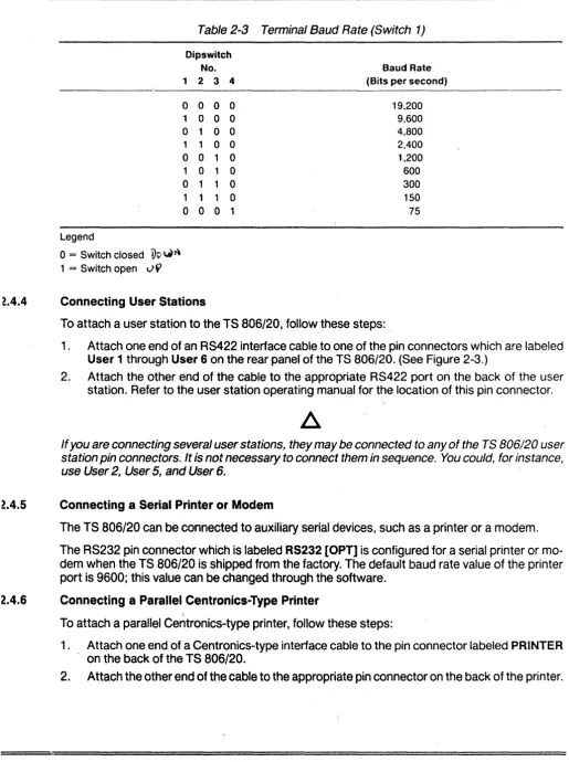
Table 2-3 Terminal Baud Rate (Switch 1)
Legend
o
= Switch closedVv
~J\ 1 = Switch openv
9
Dipswitch No.
1 2 3 4
0 0 0 0 1 0 0 0
o
1 0 0 1 1 0 0 0 0 1 0 1 0 1 0o
1 1 0 1 1 1 00 0 0 1
t4.4
Connecting User StationsBaud Rate (Bits per second)
19,200 9,600 4,800 2,400 1,200 600 300 150 75
To attach a user station to the TS 806/20, follow, these steps: .
1 . Attach one end of an RS422 interface cable to one of the pin connectors which are labeled
User 1 through User 6 on the rear panel of the TS 806/20. (See Figure 2-3.) .
2. Attach the other end of the cable to the appropriat~ RS422 port on the back of the user
station. Refer to the user station operating manual for the location of this pin connector.
If you are connecting several user stations, they may be connected to any of the TS 806/20 user
station pin connectors.
It
is not necessary to connect them in sequence. You could, for instance,use User 2, User 5, and User 6.
t4.S
Connecting a Serial Printer or ModemThe TS 806/20 can be connected to auxiliary serial devices, such as a printer or a modem.
The RS232 pin connector which is labeled RS232 [OPT] is configured for a serial printer or
mo-dem when the TS 806/20 is shipped from the factory. The default baud rate value of the printer port is 9600; this value can be changed through the software.
2.4.6 Connecting a Parallel Centronics-Type Printer
To attach a parallel Centronics-type printer, follow these steps:
1 . Attach one end of a Centronics-type interface cable to the pin connector labeled PRINTER
on the back of the TS 806/20.
2. Attach the other end of the cable to the appropriate pin connector on the back of the pr.inter.
2.
SYSTEM INSTALLATION
2.4.7 Plugging in the TS 806/20
After you have connected the TS 806/20 to all the peripheral devices, make sure the power switch is off. Then plug it into a grounded wall outlet. Do not turn it on yet.
2.5 CHECKLIST OF INSTALLATION INSTRUCTIONS
After the installation is complete, review this checklist before installing the operating system and using the system.
1 . Did you check the TS 806/20 for possible shipping damage?
2.
Is the location which you selecteda. Magnetically isolated?
b. Supplied with steady line voltage?
c. Within comfortable temperature and humidity levels?
d. Clean?
e. Spacious enough for good ventilation around the case and on a sufficiently large and
stable table?
3.· Is the power plug correct for your wall outlet?
4.
Is the outlet grounded?5.
Are peripheral devices within the distance limits specified?6.
Did you use the correct cables according to the specifications in Table 2-1 ?7. Did you check the printer baud rate compatibility?
8. Did you plug the TS 806/20 and peripherals into the wall outlet?
If your installation satisfies this checklist, you are ready to install the operating system and MmmOST.
3.
OPERATING THE SERVICE PROCESSOR·
3.1 INTRODUCTION
This chapter is designed for the person who prepares the service processor for initial operation and uses it on a daily basis.
All of the operations described in this chapter require
a
service processor terminal.3.2 INITIAL START UP
Now that all peripheral devices are installed and the TS 806/20 is plugged in I you are ready to
turn it on and install CP/M and MmmOST.
3.2.1 Power On
1. Make sure the floppy disk drive is empty before proceeding .
•
ALWAYS MAKE SURE THAT THE FLOPPY DISK DRIVE IS EMPTY WHEN YOU TURN THE
TS 806/20 ON OR OFF. IF
A
DISKETTE IS IN THE DRIVE, RESULTING POWER SURGES MAYDESTROY THE INFORMATION STORED ON THE DISKETTE.
2. Locate the ON/OFF switch on the left-center side of the rear panel of the TS 806/20.
(Fig-ure 3-1). This is a rocker-type switch.
3. Push the end which has a white dot on it to turn on the TS 806/20.
ON/OFF SWITCH
u
Figure 3-1 On/Off Switch on Rear Panel
3.2.2 Installing CP/M and MmmOST
Your system is shipped with a copy of CP/M and MmmOST on separate diskettes. This section explains how to install (transfer) a copy of these programs to the hard disk.
============_
...
3.
3.2.2.1
OPERATING THE SERVICE PROCESSOR
Booting Up-The process of transferring the operating system pr~grams to the service
processor's or user stations's memory is called booting or booting the system from the
expression to pull oneself up by one's bootstraps.
Booting the service processor the first time after you turn on the power is called a cold boot,
cold start, or reset. A cold boot clears the memory and loads the operating system programs
into it again. While a cold boot does not affect data already stored on the hard disk or on a floppy
diskette, any data in memory will be lost. A cold boot is normally used if you have a problem with
your program and wish to start over or if your system is not responding correctly.
To cold boot (reset) the TS 806/20, press the red reset button located at the left front of the
computer (Figure
3-2).
RESET BUTTON
Figure 3-2 Location of Reset Button
To load the CP/M operating system programs into the system without affecting the TS 806/20
memory areas, perform a warm boot. To warm boot the TS 806/20, press the CTRL and C keys
simultaneously (/\C) on the service processor terminal keyboard.
Whenever the service processor is warm booted, -MmmOST is cancelled and user stations are
not operable. To reinstate MmmOST, either press the TS 806/20 reset button, or enter
MMMOST<CR>
after the system prompt (ex. A».
•
BEFORE YOU WARM OR COLD BOOT THE SERVICE PROCESSOR, MAKE SURE ALL USER STATIONS ARE OFF OR NOT IN USE. IF USER STATIONS ARE OPERATING WHEN THE SERVICE PROCESSOR IS BOOTED, DATA WILL BE LOST FROM THE USER STATION MEMORY.
Addendum For:
Addendum
Document Number:
Date Issued:
TS 806/20 Computer System Installation
and User's Guide
2226501
February 24, 1983
The floppy drive illustrated in the TS
806/20
Computer System
Installation and User's Guide is not the drive that is now shipped
with the system.
The new slimline
flo~pydrive is shown below.
~
..
~- - -- --- . •... - .. ---.--_.-.. -. •.. .._ ..
-.. ---.---. -- - ---.-.---
-\.
)
TS 806/20 Computer System
To open the slimline floppy drive, turn the latch,up to a
horizontal position.
To close the drive, turn the latch down to
a vertical position.
All floppy drive storage capacity and diskette format
specifica-tions listed in the TS
806/20
manual are applicable to this
drive.
3.2.3 Procedure for Installing CP/M and
MmmOST
When setting up your system, you must install CP/M and MmmOST from
diskette onto the hard disk.
r , .~.
,
STOP
IWHEN YOU BOOT THE TS 806/20, YOU WILL FIND SOFTWARE INSTALLED ON THE
HARD
DISK.
DISREGARD THIS SOFTWARE AND INSTALL THE NEW SOFTWARE
CONTAINED ON YOUR SYSTEM DISKETTE.
After the initial installation, you should not have to repeat
this procedure unless you have problems with the hard disk.
To install CP/M and MmmOST onto the TS 806/20's·hard disk from the
TS 806/20 system diskette, follow the steps listed here. All user
responses are shown in bold print.
NOTE
IThe system boots alternately from the hard disk and the
floppy diskette.
The source of the boot will be specified in the
system message. The drive which is the source of the boot will
be considered by the system to be logical drive A until the next
boot.
1.
Connect a service processor terminal to the pin connector
labeled TERMINAL on the back of the TS 806/20.
2.
Turn on the
TS
806/20 and the service processor terminal and
wait
15
seconds.
3.
Insert the diskette into the floppy drive, and close the
drive door.
4.
Push reset and wait
10
seconds.
5.
If the system does not boot from the floppy drive, push reset
again until it does.
6.
The system will respond with a page of instructions,
followed by a system prompt (A».
7.
Enter
SUBMIT
BUILDDSK<C~>8.
Look for the following system response:
A> HDFORMAT
Hard Disk FORMAT
TeleVideo Systems, Inc. Verse
l.i
***CAUTION; ALL DATA ON THE INTEGRAL HARD DISK WILL BE
DESTROYED***
TYPE RETURN WHEN READY (ESC OR CTRL-C TO ABORT)
9.
To continue with the installation, press
<CR>
10.
Look for the following response:
FORMAT on drive 0 at Cylinder
=
XXX, Head
=
Y, Sector
=
00,
Count
=
1
where
XXX is any value between 000 and 305
Y is any value between 0 and 5
11.
Look for a possible message saying
FORMAT ERROR on Cylinder xxx, head x, sector x
If this message appears, you will see the total number of
errors given at the completion of HDFORMAT:
TOTAL FORMAT ERRORS XX
If the total is less than 50 and none of the errors occurs on
cylinder (head) 0 or 1, proceed to step 12.
If the total is 50 or more, call your distributor or dealer.
12.
Look for the following message to appear.
This message
should appear in approximately ten minutes if FORMAT
encoun-ters no errors.
FORMAT Complete
A>FIXDISK B:
FIX DISK PROGRAM VER X.O
CURRENT SCANNING BLOCK:
XXXX
where
XXXX is a changing value from 0000 to 183$
NOTE I
If there are any bad sectors, the sector numbers will be
displayed on the screen and stored in FILE.BAD, stored on
the system A directory under CP/M User 15.
13.
Look for the following message to appear:
FIXDISK COMPLETED WITH YYYY DATA BLOCK ERROR
A>FIXDISK C:
FIX DISK PROGRAM VER X.O
CURRENT SCANNING BLOCK:
XXXX
where
XXXX is a value from 0000 through 1835
YYYY is the total number of sectors with bad areas
The message will appear in approximately seven minutes if
FIXDISK encounters no errors.
14.
Add up the total data block errors
(iyyy)
f~omFIXDISK
B: and FIXDISK C: (Steps 12 and 13).
If there are more than
50 total data block errors, re-run the program SUBMIT BUILDDSK.
If
you are unable to run the program with less than 50 errors
after five tries, call your distributor.
15.
After you successfully run HDFORMAT and FIXDISK
B:
and C:
with less than
50errors, you are ready to install CP/M on
the hard disk.
Look for the following message:
A>;Type RETURN when ready to continue
A>PIP
*
16.
Press
<CR>
to continue the installation. At this point, you must press
a <CR> so the submit program will install the CP/M files on
the hard disk.
17.
Look for the following message:
; MAKESYS INSTALLS CPM ON THE FIRST LOGICAL HARD DISK
; TYPE 'C' FOR DESTINATION DRIVE
i T~PE
'TS6BOOT.COM' FOR BOOTSTRAP FILE NAME'
; TYPE 'CPM60.COM' FOR BOOS FILE NAME
; TYPE '806BIOS.COM' FOR BIOS FILE NAME
MAKESYS VER
x.y
Destination Drive?
18.
Enter
C(CR>
19.
System will display:
Bootstrap Filename (Or RETURN To Skip)
20.
Enter
TS6BOOT.COM(CR>
21.
System displays
BOOS Filename (Or RETURN to Skip)
22.
Enter
CPM60.COM(CR)
23.
System displays
BIOS Filename <Or RETURN to Skip)
24.
Enter
806BIOS.COM(CR)
25.
System displays
MAKESYS Completed ,
A)PIP B:=A:*.*[VO]
COPYING
(Several file names will follow.)
A)PIP C:=A:*.*[VO]
COPYING
(Several files names will follow.)
l
\/~~lll(.$.'~r. C1-:
'ir &:. l?f.'[.'TCV,[I;'\ '. v ... r. (
l'lM nii..·,;,;.' ... ~
~;~, I: (,J . , ' ".;
~~'" ."t;,).> t:':~
F:"~-J~. >~ .. : i
26.
System displays
TO INSTALL THE MmmOST OPERATING SYSTEM SOFTWARE:
1. RESET THE SYSTEM, WHICH WILL THEN BOOT FROM THE HARD DISK
2. REMOVE THE DISKETTE FROM THE FLOPPY DRIVE
3. INSERT THE MmmOST SOFTWARE DISKETTE LABELED 'DISK 1 OF 2'
4. TYPE:
SUBMIT COPYMST
27.
Press the reset button.
28.
Remove the system diskette from the floppy drive.
29.
Insert the first MmmOST floppy diskette labeled "DISK
IOF 2"
in the floppy drive and close the drive door.
30.
Enter
SUBMIT COPYMST<CR>
31.
Look for the following series of messages to appear:
; .MmmOST SOFTWARE INSTALLATION SUBMIT FILE (FOR
TS-806/20)
; COPIES ALL FILES FROM THE MmmOST DISKETTE LABELED
; 'DISK 1 OF 2' TO THE HARD DISK DRIVES A:
~NDB:
PIP A:=C:*.*[VO]
PIP B:=C:*.*[VO]
32.
Several file names will follow.
The screen will then display:
*
?
•
33.
-7
34.
·
,
·
,
;·
,
REMOVE THE DISKETTE FROM THE FLOPPY DRIVE
IF
YOUelll31t
HAVE 16-BIT USER STATIONS, PRESS RESET TO
ACTIVATE THE MmmOST OPERATING SYSTEM
IF YOU DO HAVE l6-BIT USER STATIONS,
INSERT THE MmmOST DISKETTE LABELED 'DISK 2 OF 2' INTO THE DRIVE
AND PRESS 'RETURN' WHEN READY TO CONTINUE
PIP
If you have only 8-bit user stations, you do not need to copy
the files on the second MmmOST diskette.
Press the reset
button to activate MmmOST.
User stations are now operable.
If you have l6-bit user stations and 8-bit user stations,
insert the MmmOST diskette labeled "DISK
2
OF 2" into the
floppy
drive. Press
<CR>
to copy the files on this diskette to the hard disk.
35.
The following messages will be displayed:
PIP A:=C:*.*[VO]
PIP B:=C:*.*[VO]
A>PRESS RESET TO ACTIVATE THE MmmOST OPERATING SYSTEM
36.
Press the TS 806/20 red reset button twice or type MMMOST<CR>.
This will activate the MmmOST program.
3.2.4 System Message
Once you have installed CP/M and MmmOST, the service processor
terminal will display a system message whenever the TS 806/20
is cold booted (turned on or reset).
Figure 3-3 illustrates the
system message.
TeleVideo Systems TS 806/20 V X.X
. xxK CP/M Verse x.x
Tandon TM-603s Winchester
MMMOST
authorized dealer:
TVInc
license:
XXXXXXXX
MmmOST Vx.y
(C) 1982 TeleVideo Systems TS-806/20
XX/XX/XX ver. x.y
. Figure 3-3 Service Processor Terminal System Message
~.
OPERATING THE SERVICE PROCESSOR
Table 3-1 Hardware Error Abbreviations
Abbreviation
DM~
CTe
510 #1 510#2
woe
FOC
Description
Direct memory access controller Counter timer circuit
Serial I/O controller Serial I/O controller Winchester disk controller Floppy disk controller
If you see this message, push the reset button once or twice. If the message still appears, call your dealer or distributor. If you are unable to see the system message or the hardware error message, or if you see obviously incorrect or garbled information, refer to Chapter 7, Mainte-nance and Troubleshooting .
• . r
OPERATING THE USER STATIONS
.1 INTRODUCTION
Your user station may be one of many user stations connected to the service processor. In most ways your user station operates as it would in a single-user system. This chapter explains how to use your user station in the multiuser environment and take advantage of the many features
offered by the system. .
.2
TURNING ON THE USER STATIONBefore operating your user station, you must be sure the TS 806/20 is turned on. To verify that the TS 806/20 is on, turn on your user station and look for this message:
TeleVideo CP/M VX.X
DISTRIBUTED PROCESSOR VX.Y
Proc.ID XX
<=>
YA>
Whenever you see this message after cold booting your user station, you will know the TS 806/20 is also turned on.
The A> is called the prompt. Prompts vary from one computer system to another but almost
always indicate that the operating system is ready for your response. While you are using an application program, you may see a different prompt symbol; this will be explained in the appli-cation program instructions.
~.3 TYPES OF DRIVES IN THE MULTIUSER ENVIRONMENT
~.3.1 Physical and Logical Drives
The hard disk drive and the floppy disk drive of the TS 806/20 are physical objects and are called physical drives.
The physical hard disk is divided into imaginary drives. These drives are called logical drives. A
logical drive does not have any physical qualities (as opposed to the hard disk and floppy disk drives). A logical drive serves as a recognizable area of the hard disk on which the computer can store and organize information.
The number of logical drives may vary from computer to computer. The TS 806/20 hard disk has. two logical drives; they are designated A and B. The logical drive designation for the floppy disk drive is C.
You can tell which logical drive is being used (is active) by looking at the letter before the prompt (Le., A». For example, B> would mean that drive B is active.
Table 4-1 illustrates the logical drive designations and their corresponding physical drives in a multiuser environment. These designations can be changed later; refer to MmmOST Program-mer's Manual.
4.
OPERATING THE USER STATIONS
Table
4-1
TS 806/20 Logical and Physical DrivesLogical Configuration Drive When Shipped *
A Private
8 Public (Shared)
C Public Only M,N Local O,P
Note
*See 4.3.2 for explanation of private and public.
Corresponding Physical Drive
Hard disk Hard disk Floppy disk
User stations' physical drives (hard disk and/or floppy disk drives)
Whenever you cold boot your user station, you automatically access drive A. This is called the default drive since it is accessed in the absence of other instructions.
It is important to correctly identify logical drives when using CP/M commands and utility programs.
The capacities of the TS 806/20 logical drives are shown in Table 4-2.
Logical Drive
A 8 C
*In megabytes (millions of bytes)
Table
4-2
Logical Drive CapacitiesApproximate Formatted Capacity· 7.328 7.344 0.342 Maximum Directory Entries 2048 512 64
Each user station can access logical drives A, B, and C. If the user station has a storage device
of its own, the logical drive designations for those physical drives will be M, N, 0, or P.
4.3.2 Private and Public Drives
A private drive is a logical drive on which each user station has its own private area to store and
acces~ information. A public drive is a logical drive to which all user stations have access.
When the MmmOST system'diskette is shipped, logical drive A is designated as a private drive and drives Band C are public drives. CP/M and MmmOST are stored on drive A. CP/M and MmmOST programs and commands are located on public drive B.
Public drive B has the capacity of containing files that are shared. Shared files are those to which several users may write simultaneously. This does not mean that a user may write to the same record (a single listing of information in a file; i.e. one employee's information in a company's payroll file) at the same time as another user. However, by using shared files, the second user does not have to wait until the first user completes all updates to the whole file. Rather, as soon as the first user completes updating a record, the second user may read.the updated record and use it.
OPERATING THE USER STATIONS
For more information on public and shared files, refer to the MmmOST Programmer's Manual.
t.3 Private and Password Directories
Logical drive A contains six private default directories (one for each user station) and ten pri-vate password directories. These directories can be reconfigured; refer to the MmmOST Pro-grammer's Manual.
A private default directory is the area which is accessed by a particular user station when it is first turned on (unless the 9perator had previously logged onto another directory). A private password directory is a directory accessible only when a password is entered. You can access a
password directory from any user station attached to the TS
806/20.
A password can, ifde-sired, be assigned to a private default directory. This would allow you to access your default directory from either your user station or from any user station (using the assigned password).
Each password directory has a preassigned password when MmmOST is shipped; these can be changed. Refer to the MmmOST Programmer's Manual.
BOOTING THE USeR STATION
You can warm boot the user station by pressing 1\ C when it is the first character entered in
re-sponse to a system prompt and in applications programs when allowed.
If you are not familiar with the term "boot," refer to 3.2.2.1.
5 OPERATING UNDER MmmOST
When you are operating in a multiuser environment using MmmOST, you will notice
a
fewdiffer-ences in the methods used to access directories and to print files. The next sections describe how to perform those functions using MmmOST.
5.1 Accessing Directories
When you turn on your user station (providing the TS 806/20 has already been turned on), you will see the following display:
TELEVIDEO CP/M VX.X
DISTRIBUTED PROCESSOR VX.Y Proc.ID XX <=> Y
A>
As explained in 4.2, the A> is a prompt which tells you that the user station is accessing logical drive A. To change to a different logical drive, enter the le.tter designation for the drive you want, followed by a colon and <CR>.
For example, if you are on logical drive A and want to access drive B:, enter
B:<CR>
You will see the following display:
B>
4.
OPERATING THE USER STATIONS
4.5.2
Calling.Up
a Directory4.5.3
To call up a directory, enter
dir<CR>
in response to the system prompt.
If you want a directory on a different logical drive, enter
dir [drive:] <CR>
where:
drive: is the d~ive on which the directory you want to access is located.
If the user station is turned off and then on, while the TS 806/20 continually operates, the user station will access the directory it was in prior to being turned off. For example, if the user station was in a password directory when turned off (and the TS 806/20 remained on), it will access the same password directory when turned on again. Likewise, if the user station was in its default directory when turned off (and the TS 806/20 was still on), it will access that default directory when turned on again.
To find out which directory the user station is in when turned on, call up a directory. By looking at the directory file names you created, you can tell which directory you are accessing. If you dis-cover your user station is in a private password directory, enter
LOGON <CR>
to change to the private default directory.
For more information on using the CP/M command DIR (calling up a directory) and on accessing different drives, ref.er to the Digital Research CP/M User Manual.
Using LOGON
To access your private password directory, you will use a program called LOGON.
When the system is shipped, LOGON is stored on public drive B. (The program can be moved to your private default or password directory through the CP/M program PIP). To locate LOGON, you can use the normal CP/M dir command.
To use LOGON, enter one of the following commands
[drive 1:] LOGON [drive 2:] [password] <CR> or
[drive 1:] LOGON [drive 2: or *:] <CR>
where:
[drive 1 :] is the logical drive on which LOGON is stored (if it is not on the drive which you are currently accessing)
[drive 2:] is the drive on which the directory or file you want to use is stored. If you enter both drive 2 and a password, you will have access to drive 2 only if your password is valid for a directory on that drive.
If you do not specify drive 2, you will have access to directories or files on all private directories on all drives that contain directories for which that password is valid.
OPERATING THE USER STATIONS
If the second form of the LOGON command is entered (drive or asterisk), do not enter a pass-word. You will be prompted
*
by the system.
After you see this prompt (*), enter your password. Your password will not be displayed on the user station screen as you type it. (Deletions are not allowed.) This method allows you to keep your password a secret from bystanders.
The system will respond:
End of Execution
A>
To determine if you have accessed your password directory, enter
DIR <CR>
The system will respond by displaying the file directory of your private password directory.
For example,
you are currently on drive B
LOGON is on your default directory on drive A
you wish to access your password directory which is named PERSONAL and is on drive A:
Your entry would be as follows:
A:LOGON PERSONAL <CR> or
A:LOGON [A: or *:]
<CR>
You will see the following display if you successfully executed LOGON:
End of Execution
A>
You enter
DIR<CR>
You will now see your password directory named PERSONAL which is on drive A.
Until you create your private default and password directories by creating and storing files, you will not see a list of files on those directories. The space for that directory is there. but since no files have been stored yet, the display will respond with NO FILE when you try to call up a directory.
4.
OPERATING THE USER STATIONS
If you enter incorrect information when executing LOGON (such as incorrect password/drivE association or an' invalid password) or if you try to access a password directory when it is a/read) in use, you will see this message in response to the LOGON command:
Unsuccessful End of Execution
Check your input, make necessary corrections, and re-enter the LOGON command.
4.5.4 Directory Configurations
When Shipped, the TS 806/20 logical drive A provides for six private default directories and ter
private password directories. These configurations can be changed through the MmmOST pro· gram GENPARMS; refer to the MmmOST Programmer's Manual.
Possible directory configurations include the following:
1 . User has only a private default directory.
2. User has a private default directory and a separate password directory.
3.
User has only a private default directory which has been assigned a password.4.
User has a private default directory (which has been assigned a password) and a separatEpassword directory.
Assigning a password to your default directory allows you to access that directory from any user
station attached to the TS 806/20.
4.6 WORKING WITH MmmOST
MmmOST is a special program which works with CP/M and enables multiple users to share ap-plications programs, peripheral devices (such as printers), and the hard disk. (Refer to the MmmOST Programmer's Manual for more detailed information.)
When the TS 806/20 is turned on or reset, MmmOST is loaded into its memory. When a user
station is also turned on, CP/M is loaded into the user station's memory from the TS 806/20. A1
this pOint, you will see the user station message
TeleVideo CP/M VX.X
DISTRIBUTED PROCESSOR VX.Y
Proc.ID XX
<=>
YA>
4.6.1 Printing With MmmOST
MmmOSTaliows users to share a printer connected to the TS 806/20. When you want to print
a
file, you can use any of the following commands:
1.
CP/M PIP2.
CP/M "p3. A word processing applications program print command (e.g., pin WordStar)
L
OPERATING THE USER STATIONS
~.S.1.1
LS.1.2
1.6.1.3
When a user enters one of these print commands while using MmmOST, a delay will occur be-fore the desired file is actually printed out. This delay is due to the print spooling process which occurs within MmmOST. Print spooling is the process in which a temporary file is created to store the data before it is printed. This temporary file is called the print spool file.
The printer prints the contents of the print spool file in the sequence in which the files are re-ceived. If another user has sent text to the print spool file before you did, his text will print out first. Print spooling under MmmOST works on a first-come, first-served basis.
Using PIP to Print-To print using the CP/M PIP command, enter the following in response to the prompt:
PIP LST:
=
<source drive:>file name <CR>where:
LST: is the designation of the logical printer device
<source drive:> is the logical drive on which the file is presently located
file name is the name of the file to be printed
Refer to the Digital Research CP/M User Manual for more information on PIP.
Using A P to Print-To print a file using the CP/M command 1\ P, enter 1\ P followed by another
command (such as TYPE or DIR). These commands tell the system what to print. For exampre, if you want to print a file while "typing" it, enter
I\PTYPE <file name> <CR>
1\ P will not be displayed on user station terminal screen.
Once a I\P is given along with another command, the print spooling process starts creating the temporary print spool file. You will see the file on the user station screen. When you come to the end of the file or text to be printed, enter another AP. This second AP will send the print spool file to the printer, and the printing process will begin.
Ref~r to the Digital Research CP/M User Manual for more information on AP.
Using Print Command in a Word Processing Program-To print a file using a word processing applications program such as WordStar, use the print command in that program. Once you have entered the command and answered program-prompted questions, the temporary spool file is created. At this point, you will probably see the main word processing menu on the screen.
To begin the actual printing process, you must warm boot the system using the appropriate "exit to system" command (Le. AX in WordStar).
Remember, there will be
a
delay between the moment the first print command is entered andwhen the actual printing begins (due to print spooling). This applies to each example (PIP, \ P. and word processing print command) in this section.
For additional printing features, refer to the MmmOST Programmer's Manual.
5.
OPERATIONAL GUIDELINES
5.1
INTRODUCTIONThis chapter will describe procedures which can prevent damage to your diskettes and possible loss of data.
5.2
FLOPPY DISKETTESFloppy diskettes provide additional storage space for the TS 806/20 user. Applications pro-grams, text, data, and programs which operate the system can be stored on diskettes. User stations attached to the TS 806/20 can access the floppy diskette contained in the floppy disk
drive by referring to drive
C. Once the user has accessed drive C, all read and write functions can
be performed on files contained on the floppy diskette.
5.2.1
Inserting a Floppy DisketteTo insert a floppy diskette into the floppy drive, put your finger under the doorhandle of the drive and open it gently.
Figure
5-1
Opening Floppy Drive DoorBEFORE TURNING POWER ON OR OFF, ALWA YS MAKE SURE THE DRIVE DOOR IS OPEN.
When power is turned on
or
off, the power may surge, damaging information stored on thedisk-ette or the diskdisk-ette itself.
If
the drive door is open, the disk head is away froin the diskettesurface.
Take the diskette out of its white paper jacket. Hold the diskette by the edge of the black plastiC cover.
5.
OPERATIONAL GUIDELINES
Figure
5-2
Removing Diskette from Jacket
A
void touching the surface of the diskette (which shows through the openings on the cover) with
your hands or the diskette may be damaged.
The small notch which is cut out of one side of the diskette near the label allows the disk head to write on the disk.
DI ____ _
O.
I
Figure
5-3Write-Protecting Diskette
When the notch is covered, the write mechanism is not allowed to function and information on the diskette cannot be overwritten accidentally. Put a Write-Protect tab (furnished with each package of blank diskettes) over the notch on the system diskette. (Refer to 5.3 where Write Protection is discussed.)
Turn the diskette so the label is near you and facing up and the notch is on the left side.
5.
OPERATIONAL GUIDELINES
I
Figure 5-4 Holding Diskette Before Insertion
Hold the diskette level, with the notch on the left side and the oblong hole in the diskette cover towards the back of the diskette. Insert it in the opening of the floppy drive. Using the tip of your finger, push it gently in the rest of the way.
~~I!~
~==~:::::::~
--.. --- ... -.. -..
-.---.-="."'=-=-... -,=.",.-===-=~=-: . ."-. .". _._ .. __ .._-Figure 5-5 Inserting Diskette in Floppy Drive
5.
OPERATIONAL GUIDELINES
If the diskette seems to catch slightly, pull it out slightly and push it in gently again. DON'T
FORCE IT IF IT RESISTS.
Close the drive door slowly.
5.2.2 For·matting
Your hard disk and the system diskette contain a utility program called FORMAT, described in Chapter 6. This program superimposes messages on your blank diskette which serve as refer-ence points for the system later. During formatting, any data already on the diskette is erased and the diskette is prepared for new data. The diskette is divided up into tracks (very much like grooves on a phonograph record) and then again into wedges called sectors.
Since each computer system has its own format requirements, blank diskettes are not format-ted by diskette manufacturers. Before you can use a new diskette, you must first format it for your system. Diskettes formatted on a TeleVideo system can be used on any TeleVideo floppy-disk system.
ROTATION
---
~--,-SECTORFigure 5-6 Diskette Tracks and Sectors
Detailed instructions on using the utility program FORMAT can be found in Chapter 6.
5.2.3
Caring for Diskettes
Although diskettes look sturdy, they can be easily damaged by scratches, fingerprints, magnetic fields, or liquids. If the diskette is damaged, the system can no longer read the diskette. This
section explains how to handle and store diskettes so their useful life is p~olonged and the data
stored on them protected.
).
OPERATIONAL GUIDELINES
i.2.4 Handling Diskettes
Each diskette arrives in a white paper jacket. Do not discard this paper jacket, as it protects the
diskette, prolongs its life and ensures the accuracy of the information on the diskette.
Although you can see parts of the diskette through openings in the black cover, NEVER touch the magnetic surface of the diskette itself. Objects touching the surface can cause scratches, and oil from your skin can damage the surface. Whenever the diskette is not in the drive, keep it in the white paper jacket; otherwise the normal dust and chemicals in the air will shorten its life expectancy.
The diskette is encased in a black plastic cover. NEVER try to remove the black plastic jacket. This jacket contains cleaning agents and lubricants which prolong the life of the diskette.
Even with the black jacket around the diskette, the diskette can be damaged. Anything which creases, mutilates, or distorts the surface of the diskette (e.g., paperclips, staples, and ballpoint
pens) will keep it from operating correctly later. You will prolong the life of your diskettes if you
follow these rules:
NEVER attach anything to the diskette with paperclips or staples.
NEVER fold or mutilate the diskette.
Write on the diskette label only with a soft felt-tip pen. Press lightly. (Better yet, write on the label BEFORE putting it on the diskette.) NEVER write on the diskette label with a pencil or ballpoint pen or while the diskette is under your writing surface.
Figure 5-7 Diskette and Protective Lining Inside the Protective Black Plastic Enclosure
The diskette can also be damaged by careless handling. Hold the diskette GENTLY by the cor-ners or on the edge. DO NOT BEND ITI (Think of the diskette as a photographic negative where you must hold it by the edges to avoid putting fingerprints on it.)
After the diskette is inserted in the drive, close the door slowly.
5.
OPERATIONAL GUIDELINES
5.2.5 Storing Diskettes
Store diskettes in an UPRIGHT position in one of the excellent dustfree containers available on the market. Keep this container in a cool place. Diskettes left in direct sunlight or in a hot area (such as a hot car) even for a short time can warp. If this happens you may not be able to retrieve the data.
Diskettes are made of magnetically-treated mylar. Even temporary exposure to magnetic fields can erase the data. Magnetic fields are around many items commonly found in an office environment, such as:
Telephones .
Magnetic paperclip holders
Typewriters
Adding machines
Television sets
Even the bell in a telephone can damage the diskette if the telephone is resting on the diskette when the telephone rings.
As soon as you remove a diskette from the drive, put it back in the white jacket and in the stor-age container. If you need to ship diskettes, you can purchase speCial mailing protectors.
5.3 WRITE PROTECTING DISKETTES
When information is copied onto a diskette, it may erase or superimpose new data on the infor -mation originally there. If the infor-mation on a diskette is particularly important, you may want to
protect it against accidental erasure by write-protecting the diskette.
To write-protect a diskette, place one o