IJEDR1503091 International Journal of Engineering Development and Research (www.ijedr.org) 1
Mechanical properties and structural evolution during
Warm Forging of Carbon Steel
1Ashutosh Kumar, 2Ajit Kumar, 3Rohit Kumar 1Student, 2Student, 3Student
1Department of Foundry and Forge Technology, 1NIFFT Ranchi, India
________________________________________________________________________________________________________
Abstract-Warm forging is the plastic deformation of a metal at temperatures below the recrystallization temperature
range and above room temperature; typically in the temperature range of 600-900ºC. Warm working combines the advantages of both cold and hot working. Compared to cold/hot forging, warm forging offers the advantages of fewer forming steps as a result of greater workability, reduced loads, energy savings, high material utilization. This work has done on En 24 and 1018 low carbon steel to establish quantitative knowledge of mechanical properties occurring during the warm working at the temperature of 800°C with the help of different processing parameters (amount of deformation, soaking time and strain rate). The paper shows that the hardness, toughness and strength increases with increase in deformation after warm forging. It also affects the toughness value. Microstructure along with volume percentage of retained austenite also estimated to get proper explanation for high or low toughness. Finally optimum forging and parameters are used to impart the benefits of warm forging than cold or hot forging for carbon steel.
Index Terms-Warm Forging, Hardness, Toughness, Strength, Low Carbon Steel.
________________________________________________________________________________________________________ I. INTRODUCTION
Warm forging is the plastic deformation of a metal at temperatures below the recrystallization temperature range and above room temperature; typically in the temperature range 0.3-0.6 of the melting temperature (Tm).
In steels, however, due to the occurrence of blue brittleness around 0.3 Tm the warm working range usually quoted is 0.5-0.65 Tm; between 600-900°C. Ferrite brittleness and scaling factor is limiting for this working temperature range. Warm working involves the heating of the material to the working temperature and deforming it at that temperature. This is distinct from other processes such as controlled rolling where the material is deformed at a higher temperature followed by finishing deformation in the warm working temperature range [1].
In the recent past there has been growing interest in warm working with the aim of combining the advantages of both cold and hot working, primarily regarding forging. Compared to cold forging/rolling, warm working offers the advantages of fewer forming steps (i.e. a reduced number of dies in forging) as a result of greater workability, reduced loads due to higher deformation temperatures, energy savings due to elimination of in-process annealing treatments and high material utilization from cold and hot forging [1].
As the carbon percentage content rises, steel has the ability to become harder and stronger through heat treating; however it becomes less ductile. Regardless of the heat treatment, higher carbon content reduces weldability. In carbon steels, the higher carbon content lowers the melting point [2].
In practice, warm working has been shown to be an economical manufacturing method for forging precision parts that are (a) difficult to cold work because of workability or press-capacity limitations, or (b) cannot be hot worked because of surface finish or dimensional requirements. Ceramic inserts and coatings are well established in the machining industry for reducing tool and die wearing. It is very difficult to maintain the forging temperature throughout the process. High-speed warm forging is very limited. However, the full potential of warm working has not yet been utilised, particularly in rolling, due mainly to a poor knowledge of the metallurgical and operating parameters. Warm working cannot simply be carried out by applying the established practice of cold or hot working at an appropriate intermediate temperature, it requires a technology of its own. The implementation of warm forging is limited by high investment costs for the rearrangement of machines and expenses for tools and development. Consequently a large volume of work has been carried out in the last twenty years on various aspects of warm working technology. Warm forging is a relatively new process that became known in early 70s. While it is more established in the industry of East- Asian countries and Japan, warm forging is not used wide spread in Europe [3].
Steel undergoes a metallurgical phase transformation at temperatures within or slightly above the warm-forging range. This transformation is associated with a change in volume distinct from that which is due to purely thermal effects. It occurs over a range of temperature that is dependent on alloy content. Depending on the requirements of a particular application, the warm-forging temperature may be below, within, or above the transformation temperature range. With respect to ferrous materials, warm forging is becoming more and more common as a means of increasing precision [4].
IJEDR1503091 International Journal of Engineering Development and Research (www.ijedr.org) 2 V Soleymani et.al [6] have studied the grain refinement in a low carbon steel through multidirectional forging. Grain refinement is one of the successful and low-cost methods to develop metals having excellent combination of strength and ductility. Low carbon steel was deformed by using multidirectional forging (MDF) technique at room temperature. The influence of strain amount and annealing process on the microstructure and mechanical properties of investigated steel was studied. The grain refinement mechanism was studied by the microstructure observation.
In warm-forging, the flow stress becomes very complex with the change of temperature, strain, and strain rate. Among these factors, the influence of temperature is most significant. Thus a proper forming temperature range is very important in warm-forging, which will be helpful in reducing forces and work energy, eliminating defects, and advancing the metal flow [7].
II. EXPERIMENTAL PROCEDURE
Material used- (i) EN-24 low alloy steel (ii) AISI 1018 low carbon steel Composition of EN-24 low alloy steel-
Carbon 0.4% Silicon 0.2%
Nickel 1.5% Manganese 0.5%
Chromium 1.2% Phosphorous 0.04%
Molybdenum 0.3% Sulphur 0.03%
Typical Mechanical Properties of EN-24 as shown in table no.1
Table 1: Mechanical Properties of EN-24 Ultimate Tensile
(N/mm²)
Yield (N/mm²)
Elongation %
Toughness Joule (Upto 150mm
sample size)
Hardness Brinell
850-1000 650 13 50 248-302
Composition of AISI 1018 low carbon steel-
Carbon 0.18 % Phosphorous 0.04 %
Iron 98.81% Manganese 0.7 %
Sulphur 0.05%
Typical Mechanical Properties of AISI 1018 low carbon steel as shown in table no.2
Table 2: Mechanical Properties of AISI 1018 low carbon steel Ultimate
Tensile N/mm²
Yield strength N/mm²
Elongation %
% Area reduction
Toughness Joule (Upto 150mm size of sample)
Hardness Brinell
440 370 15 40 17 285
Size of the billet cut: Billet having 40mm diameter of both the steel were taken for warm forging at 800ºC temperature and cut according to the required length of sample for warm forging as obtained by the calculation.
III. CALCULATION
Volume of the raw material = Volume of the sample after warm forging π R2L +10% scale loss of raw material volume = π r2l
11÷ (10 π R2L) = π r2l ……… equation (i)
Here, R=Raw material sample radius =20mm, r= forged sample radius, L=Length of raw sample, l=Length of forged sample=120mm
Here deformation has done by reducing the diameter and elongate the length of the sample. Here we have to find out ‘L’. In case of 30% deformation forged sample radius (r) = 14mm, then from (i) L≈54mm………equation (ii)
In case of 40% deformation forged sample radius (r) =12mm, then from (i) L≈40mm ……… equation (iii) IV. EQUIPMENTS USED
After heating in electric muffle furnace both samples were forged in two different forging equipments (i) Pneumatic hammer and (ii) Hydraulic press. The details of these equipments are given below.
Pneumatic hammer- The pneumatic hammer is the most inexpensive and versatile type of equipment for generating load and energy, to carry out a forging process. It is most commonly used forging equipment, especially in forging of steel, in small and medium size production lots. During a working stroke, the deformation proceeds until the total kinetic energy is dissipated by
Capacity- 250kg (max.)
Company Name- New standard engineering Co. Ltd. (India) and B.S. Massey Ltd.(England).
IJEDR1503091 International Journal of Engineering Development and Research (www.ijedr.org) 3 plastic deformation of the forging stock and by plastic deformation of the ram and anvil, when the die faces contact with each other. A typical pneumatic hammer was used in this process as shown in fig.1.
Fig.1: Pneumatic hammer
Hydraulic press- Hydraulic presses are operated by large pistons driven by high-pressure hydraulic or hydro pneumatic systems. The basic difference between hydraulic press and other methods is that pressure is applied in a squeezing manner rather than by impact. Hydraulic presses are two types; one is direct driven, which operate with hydraulic fluid (oil or water) pressurized directly by high-pressure pumps. Second one is hydro pneumatic presses, which operate with hydraulic fluid supplied from accumulators that are pressurized by high pressure pumps.
These machines are used for both open die or closed die-forging operations. In closed die forging of small and medium size parts, hydraulic presses are used either for preforming or for forging of aluminium and magnesium alloys, where die chilling does not present any problems. Most of the load is available during the entire stroke. So hydraulic presses are ideally suited for extrusion type forging operations requiring nearly constant load over a long stroke. A typical hydraulic press has used for this process as shown in fig. 2.
Fig.2: Hydraulic press
Electric muffle furnace- It is an electric resistance furnace in which a refractory envelop surround by the electric coil and electrode provides the necessary heat through eddy current flow when power is applied to the primary coil surrounding the charge. This furnace operates noiselessly. The furnace involves high operational costs. A typical electric muffle furnace was used in this process a shown in fig. 3.
Fig.3: Electric muffle furnace
V. FLOW CHART OF EXPERIMENTAL PROCEDURE
Experimental procedures have done according to the flow diagram as shown in fig. 4. Unit-lb/sq. inch
Pressure-4480lb/sq. inch Capacity- 6000lb/sq. inch Make- Fielding & Platt Ltd.,
Name-Iherelek
IJEDR1503091 International Journal of Engineering Development and Research (www.ijedr.org) 4 Fig.4: Flow chart of experimental procedure
VI. DESCRIPTIONS OF EXPERIMENTAL PROCEDURES
The billet was cut for warm forging of low alloy steel EN-24 and AISI 1018 low carbon steel as per the required dimension. Then it was heated in electric muffle furnace at 800ºC with two different soaking time 30 minutes and 1 hour. Now forging has done with two different rate of deformation, 30% and 40% in two different equipments, pneumatic hammer and hydraulic press of each samples. Then forged samples were cooled in air. After that mechanical properties (UTS, yield strength, % elongation, % area reduction, toughness, hardness) have found out.
Mechanical properties:
IJEDR1503091 International Journal of Engineering Development and Research (www.ijedr.org) 5 Fig.5: Universal Tensile Testing Machine
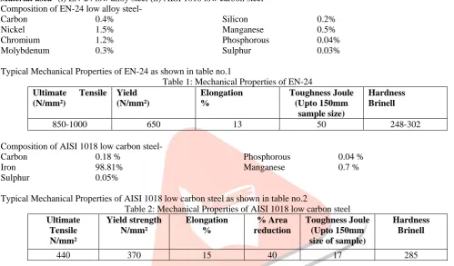
The dimension of the standard sample for tensile test piece has taken with gauge length =60mm, length =120mm, radius =5mm which are shown in fig. 6.
Fig. 6: Tensile test piece with dimension
Sample size-
For 40% deformation-(i) 40mmX40mm (Φ)...(for tensile test piece)…from(iii) (ii)20mmX 40mm (Φ)...(for impact test piece)..from(iv) For 30% deformation-(i) 54mmX40mm (Φ)...(for tensile test piece)…from(ii) (ii) 25mmX 40mm (Φ)....(for impact test piece)…from(v) Now as the impact test piece is of square cross-section of side (say ‘a’)
Converting the above circular cross-section as mentioned for tensile test piece into a square cross-section of equivalent area. Area of circle = area of square
Or, 𝜋𝜋
4 x d2 = a2
Or, a2 = 3.14x28x28
4
Or, a = �3.14x428x28
Or, a= 24.80 mm ≈ 25 mm………equation (iv) Similarly for 40% deformation
a= 21mm ≈ 20mm……… equation (v)
Formulae:-
Ultimate Strength = maximumload
originalcrosssectionalarea ---(1)
Yield Strength = Yieldpointload
originalcrosssectionalarea ---(2)
Percentage elongation = �finallength –initiallength
initiallength � x 100 ---(3)
Percentage reduction in area = �initialarea – finalarea
initialarea � x 100 ---(4)
Toughness= mass X acceleration due gravity (g) X difference of height ----(5)
Impact test- This test gives the toughness value of the material. Which signifies the amount of energy absorbed by a material at the time of fracture under impact loading, where a notched bar prepared as per standard from the test material, is held in a vice and a weight is allowed to swing from a known height in such a way that it hits the notched bar in its path and breaks it. Since the material has absorbed some amount of energy during its fracture, the swinging mass losses part of its energy and therefore will
Capacity-30 kg
Model No.-130/167
40 divisions of scale on machine=3cm
Make- Switzerland
Universal tensile testing machine model no.-52/191
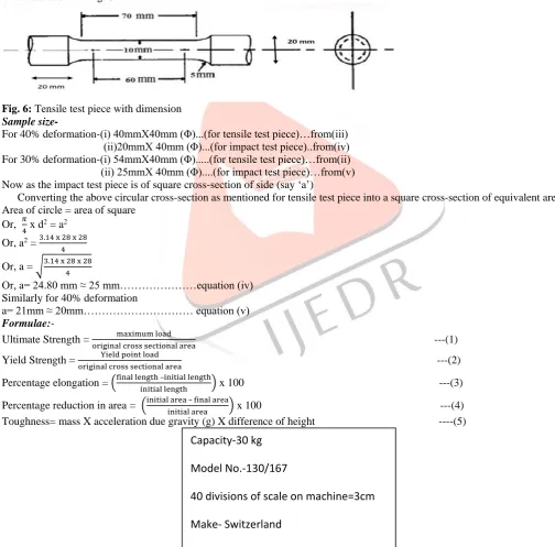
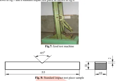
IJEDR1503091 International Journal of Engineering Development and Research (www.ijedr.org) 6 not be able to reach the same height from where it started. The loss in height multiplied by the weight represents the energy absorbed by the specimen during fracture, which can be directly measured from the indicator on the tester. A typical Izod test machine has shown in fig.7 and a standard impact test piece as shown in fig.8.
Fig.7: Izod test machine
Fig. 8: Standard impact test piece sample Hardness
With the help of Brinnel hardness testing machine as shown in fig.9 hardness test has done of each sample. The Brinell hardness test method consists of indenting the test material with a 10mm diameter hardened steel to a load of 3000kg. For softer materials the load can be reduced to 1500kg or 500kg to avoid excessive indentation. The full load is normally applied for 10 to 15seconds in the case of iron and steel. The diameter in the indentation left in the test material was measured with a low powered microscope. The hardness value of the corresponding diameter of indentation was noted from the data table of BHN. Total 3 values of BHN have taken in 3 different locations on the sample and finally average value of all BHN values were calculated for all samples.
Fig. 9: Brinell Hardness Testing Machine VII. RESULTS &
DISCUSSION-Variation of tensile properties for forged steel in pneumatic hammer:
Table no.3 shows the properties of 1018 low carbon steel at different rate of deformation with different soaking time as per given calculation in equation (1,2,3,4).
Table 3: Tensile properties of 1018 low carbon steel in pneumatic hammer
Soaking time Deformation Tensile properties
UTS MPa
Yield Strength MPa
%Elongation %Reduction in Area
1 hour 40 % 541.1 363.06 20 46.71
30% 518.61 358.85 20.33 39.16
30 minutes 40% 503.62 375.75 20.5 49.59
Max. Load- 3000 kg Min. Load- 250 kg
IJEDR1503091 International Journal of Engineering Development and Research (www.ijedr.org) 7
30% 494.87 363.05 18.33 43.75
Table no.4 shows the properties of EN-24 low alloy steel at different rate of deformation with different soaking time as per given calculation in equation (1,3,4).
Table 4: Tensile properties of EN-24 low alloy steel in pneumatic hammer
Soaking time Deformation Tensile properties
UTS MPa %Elongation %Reduction in Area
1 hour 40 % 1129.71 5.83 23.56
30% 1093.47 5.00 21.43
30 minutes 40% 1114.71 5.83 27.75
30% 1007.42 5.00 19
Variation of tensile properties for forged steel in hydraulic press:
Table no.5 shows the tensile properties of 1018 low carbon steel at different rate of deformation with different soaking time as per given calculation in equation (1,2,3,4).
Table 5: Tensile properties of 1018 low carbon steel in hydraulic press Soaking
time
Deformation Tensile properties
UTS MPa
Yield strength MPa
%Elongation %Reduction in Area
1 hour 40 % 506.23 369.23 21.66 46.71
30% 497.3 349.42 13.33 43.75
30 minutes 40% 497.37 350.03 14.66 46.71
30% 469.8 331.31 12.66 27.75
Table no.6 shows the properties of EN-24 low alloy steel at different rate of deformation with different soaking time as per given calculation in equation (1,3,4).
Table 6: Tensile properties of EN-24 low alloy steel in hydraulic press Soaking
time
Deformation Tensile properties
UTS MPa %Elongation %Reduction in Area
1 hour 40 % 1163 5.33 27.43
30% 1131 3.83 23.75
30 minutes 40% 1161.7 13.33 36
30% 1149 3.33 22.56
A typical fig.11 shows the tensile test piece sample which have used to find out the tensile properties.
Fig.11: Tensile test piece
Variation of hardness of forged steel in hydraulic press:
Table no.7 shows the hardness of EN-24 low alloy steel at different rate of deformation with different soaking time. Table 7: Hardness of EN-24 low alloy steel in hydraulic press
Soaking time
Deformation Indentation dia. BHN Avg. BHN
1 hour
40%
3.5 363
355.66
3.4 341
3.0 363
30%
3.25 302
346
3.34 321
3.20 415
30 minutes
40%
3.3 363
371.33
3.4 388
3.3 363
IJEDR1503091 International Journal of Engineering Development and Research (www.ijedr.org) 8
30% 3.1 321 334.33
3.2 341
Table no.8 shows the hardness of 1018 low carbon steel at different rate of deformation with different soaking time. Table 8: Hardness of 1018 low carbon steel in hydraulic press
Soaking time
Deformation Indentation dia.
BHN Avg. BHN
1 hour
40%
4.5 179
170.66
4.6 170
4.7 163
30%
4.9 149
153.66
4.8 156
4.8 156
30 minutes
40%
4.5 179
188.33
4.2 207
4.5 179
30%
4.7 163
165.33
4.6 170
4.7 163
Variation of hardness of forged steel in pneumatic hammer:
Table no.9 shows the hardness of 1018 low carbon steel at different rate of deformation with different soaking time. Table 9: Hardness of 1018 low carbon steel in pneumatic hammer
Soaking time
Deformation Indentation dia. BHN Avg. BHN
1 hour
40%
4.5 179
170.66
4.6 170
4.6 170
30%
4.5 179
168.33
4.7 163
4.7 163
30 minutes
40%
4.5 179
217
4 285
4.4 187
30%
4.4 187
193.66
4.3 197
4.3 179
Table no.10 shows the hardness of EN-24 low alloy steel at different rate of deformation with different soaking time. Table 10: Hardness of EN-24 low alloy steel in pneumatic hammer
Soaking time
Deformation Indentation dia. BHN Avg. BHN
1 hour 40%
3.2 363
379.66
3.1 388
3.1 388
30%
3.2 363
341.66
3.4 321
3.3 341
30 minutes 40%
3.2 363
357.33
3.4 321
3.1 388
30%
3.4 321
327.66
3.4 321
3.3 341
Variation of toughness of forged steel in pneumatic hammer
IJEDR1503091 International Journal of Engineering Development and Research (www.ijedr.org) 9 Table 11: Toughness of 1018 low carbon steel in pneumatic hammer
Soaking time Deformation Toughness (Joule)
1 hour 40 0.7 30 0.5 30 minutes 40 0.8 30 0.65
Table no.12 shows the toughness of EN-24 low alloy steel at different rate of deformation with different soaking time as per given calculation in equation (5).
Table 12: Toughness of EN-24 low alloy steel in pneumatic hammer
Soaking time Deformation Toughness (Joule)
1 hour 40 1.55 30 1.25 30 minutes 40 1.60 30 1.40
Toughness: Variation of toughness of forged steel in hydraulic press:
Table no.13 shows the toughness of 1018 low carbon steel at different rate of deformation with different soaking time as per given calculation in equation (5).
Table 13: Toughness of 1018 low carbon steel in hydraulic press
Soaking time Deformation Toughness (Joule)
1 hour 40 0.75 30 0.50 30 minutes 40 0.80 30 0.65
Table no.14 shows the toughness of EN-24 low alloy steel at different rate of deformation with different soaking time as per given calculation in equation (5).
Table 14: Toughness of EN-24 low alloy steel in hydraulic press
Soaking time Deformation Toughness (Joule)
1 hour 40 1.3 30 1.2 30 minutes 40 1.6 30 1.3 A typical fig.14 shows the Izod test sample were used to find out the toughness.
Fig.14: Izod test piece VIII. RESULTS & DISCUSSION
As per the experimental data obtained after warm forging of EN-24 low alloy steel and 1018 low carbon steel at different parameters the properties of materials have changed.
The ultimate tensile strength, % elongation, % area of reduction, toughness and hardness of 1018 low carbon steel increases in case of 40% deformation in pneumatic hammer with 1 hour soaking time than 30% deformation with 1 hour soaking time.
In case of hydraulic press it was found that the toughness and hardness of 1018 low carbon steel increases in 40% & 30% deformation with 30 minutes soaking time than 40% & 30% deformation with 1 hour soaking time.
The ultimate tensile strength and hardness of EN-24 low alloy steel increases in case of 40% deformation in pneumatic hammer with 1 hour soaking time than 40% deformation with 30 minutes soaking time. But toughness decreases in case of 40% deformation with 1 hour soaking time than 30% deformation with 30 minutes soaking time in pneumatic hammer.
IJEDR1503091 International Journal of Engineering Development and Research (www.ijedr.org) 10 same in this case. Here toughness increases but hardness decreases in case of 30% deformation in 30 minutes soaking time than 30% deformation in 1 hour soaking time.
In case of hydraulic press it was found that the ultimate tensile strength and toughness of EN-24 low alloy steel increases in case of 30% deformation with 30 minutes soaking time than 30% deformation with 1 hour soaking time. But hardness, % area of reduction and % elongation decreases in this case.
In case of hydraulic press it was found that the toughness, % area of reduction, % elongation and hardness of EN-24 low alloy steel decreases in case of 40% deformation with 1 hour soaking time than 40% deformation with 30 minutes soaking time. But the ultimate tensile strength increases in this case.
IX. CONCLUSION
As per the experimental data and microstructure obtained after warm forging its conclusion depends upon the following factors-
1. Soaking time
2. Amount of deformation 3. Forging equipments Effect of soaking time-
(i) Strength increases with increase in soaking time. (ii)Toughness decreases with increase in soaking time.
(iii)Hardness decreases as well as increases with increase in soaking time at different amount of deformation with different strain rate.
Effect of deformation
The amount of deformation 40% gives some significant change in mechanical properties of the material than 30% deformation. Mechanical properties increases with increase the amount of deformation.
(i) Hardness increases with increase in deformation.
(ii)Tensile strength increases with increase in deformation in case of more soaking time and vice versa. Effect of equipments used-
Because of different strain rate of hydraulic press and pneumatic hammer the mechanical properties changes. (i) In case of 1018 low carbon steel hardness decreases in hydraulic press.
(ii) In case of EN-24 low alloy steel hardness increases in hydraulic press than pneumatic hammer. (iii)Tensile strength increases in case of hammer in 1018 low carbon steel than hydraulic press. (iv)Toughness increases in case of hammer.
REFERENCES
[1] Z. Husain, Technical steel research, The kinetics of recovery and recrystallization of low alloy steels during warm working, pp 9-14
[2] Knowles, Peter Reginald (1987), Design of structural steelwork (2nd ed.), Taylor & Francis, p. 1, ISBN 978-0-903384- 59-9. [3] T.A. Dean & C.R. Anderton :Int. Journal. Mach.Tool ,14, 1974, pp,1-12
[4] Asm Hand Book Volume-14 Forming And Forging,Page No. 218-220,344,373,375
[5] Deshpande, M. and Altan, T. Selection of die materials and surface treatments for increasing die life in warm forging: pp 3541 [6] V Soleymani, B Eghbali, Journal of iron and steel research, international, 19(10), 2012 pp 74-78