ABSTRACT
SHIN, SEUNGHEE. Efficient Memory Architecture Design for Emerging Technologies. (Under the direction of Yan Solihin.)
While the amount of data needs to be processed is expected to increase exponentially in the near future, the advancement of system performance slows down due to physical limitations of transistor scaling. However, emerging memory technologies,die-stacked DRAMandNon-Volatile Main Memory(NVMM), are expected to become a new momentum for the future technology innovation by reducing performance overheads in memory accesses. Die-stacked DRAM technology enables a large Last Level Cache (LLC) that provides high bandwidth data access to the processor, and byte-addressable non-volatile memory technology allows programmers to store important data in data structures in memory instead of serializing it to the file system. On the other hand, GPUs have emerged as a first-class computing platform utilizing their massive parallel processing. In this advancement, shared virtual memory (SVM) across the CPU and the GPU is considered as one of the key features to promote GPUs into main processors by improving GPU programmability. However, we have identified difficulties in modern computer systems which are not yet prepared to efficiently utilize these new memory and GPU technologies. In this thesis, we introduce four novel approaches that propose new system architectures alleviating these difficulties.
Die-stacked DRAM is anticipated as huge LLC relieving bottlenecks in memory bandwidth, but it requires a large tag array that may take a significant portion of the on-chip SRAM budget. To reduce SRAM overhead, systems like Intel Haswell relies on a large block (Mblock) size. One drawback of a large Mblock size is that many bytes of an Mblock are not needed by the processor but are fetched into the cache. A recent technique (Footprint cache) to solve this problem works by dividing the Mblock into smaller blocks where only blocks predicted to be needed by the processor are brought into the LLC. While it helps to alleviate the excessive bandwidth consumption from fetching unneeded blocks, the capacity waste remains: only blocks that are predicted useful are fetched and allocated, and the remaining area of the Mblock is left empty, creatingholeswhich is capacity overheads. In this thesis, we propose a new design,Dense Footprint Cache(DFC) which eliminates holes on top of Footprint cache by placing blocks in Mblock contiguously. Through simulation of Big Data applications, we show that DFC reduces LLC miss ratios by about 43%, speeds up applications by 9.5%, while consuming 4.3% less energy on average.
clwb, and pcommit. These new instructions make it possible to implement fail-safe code on NVMM. In our experiments, we found that these persistence instructions in clusters along with expensive fence operations add a significant execution time overhead, on average by 20.3% over code with logging but without fence instructions to order persists. To deal with this overhead and alleviate the performance bottleneck, we propose to speculate past long latency persistency operations using checkpoint-based processing. Our speculative persistence architecture reduces the execution time overheads to only 3.6%.
Like the speculative persistence architecture, emerging non-volatile memory (NVM) technolo-gies are encouraging the development of new architectures that support the challenges of persistent programming. An important remaining challenge is dealing with the high logging overheads in-troduced by durable transactions. In this thesis, we propose a new logging approach for durable transactions that achieves the favorable characteristics of both prior software and hardware ap-proaches. We also propose a novel optimization at the memory controller that is enabled by a battery backed write pending queue in the memory controller. Since the WPQ is persistent, we drop log updates that have not yet written back to NVMM by the time a transaction is considered durable. We implemented our design on a cycle accurate simulator, MarssX86, and compared it against state-of-the-art hardware logging (ATOM[Jos17]) and a software only approach. Our experiments show thatProteusimproves performance by 1.44-1.47×, on average, compared to a system without hardware logging and 9-11% faster than ATOM which also makes 3.4×more writes to memory than our design.
© Copyright 2018 by Seunghee Shin
Efficient Memory Architecture Design for Emerging Technologies
by Seunghee Shin
A dissertation submitted to the Graduate Faculty of North Carolina State University
in partial fulfillment of the requirements for the Degree of
Doctor of Philosophy
Electrical and Computer Engineering
Raleigh, North Carolina
2018
APPROVED BY:
James Tuck Gregory Byrd
Ed Gehringer Yan Solihin
DEDICATION
BIOGRAPHY
ACKNOWLEDGEMENTS
I would like to thank my advisor, Dr. Yan Solihin, for his help and encouragement during my Ph.D. study. He is an excellent role model as a good researcher to me. I learned what I needed to become a good researcher from him. His keen insight and professional knowledge always amazed me. I also appreciate his trust in me for such a long time and his financial support. My every experience at ARPERS is so valuable and will remain forever in my life.
I also would like to thank Dr. James Tuck. I highly enjoyed the collaboration with him during my Ph.D. study. I am glad that our works ended up being accepted to such reputable venues. I also appreciate his encouragement whenever I was struggling. His support always helped me to persevere all these years.
I would like to thank Dr. Greg Byrd and Dr. Edward Gehringher willing to become a member of my Ph.D. advisory committee. I especially appreciate Dr. Greg Byrd’s recommendation letter for my job search. His support helped me to take the next step after Ph.D. degree successfully. I also thank Dr. Gehringher’s help before my preliminary oral examination when I was in trouble to find a new committee member a few days before the exam date.
I would like to thank AMD research for offering me an internship opportunity in 2017. Especially, I want to thank my mentor, Dr. Arkaprava Basu, to help me to conduct GPU researches.
I am thankful to all my lab mates, especially, Yipeng Wang, Amro Awad, Satish Tirukkovalluri, Mohammad Alshboul, Nadim Jabbour, and Maryam Babaie. I would never forget the good time we had together and all the interesting discussions.
TABLE OF CONTENTS
LIST OF TABLES . . . .viii
LIST OF FIGURES. . . ix
Chapter 1 INTRODUCTION . . . 1
1.1 Stacked DRAM as a last level cache . . . 2
1.2 Speculative Persistence on NVMM . . . 4
1.3 Software supported hardware logging on NVMM . . . 5
1.4 Scheduling Page Table Walks for Irregular GPU Applications . . . 7
1.5 Thesis layout . . . 9
Chapter 2 Dense Footprint Cache: Capacity-Efficient Die-Stacked DRAM Last Level Cache 10 2.1 Related Work . . . 10
2.2 Overview . . . 12
2.3 Dense Footprint Cache Design . . . 15
2.3.1 Cache Replacement Policy . . . 15
2.3.2 Placement Fit Policy . . . 19
2.3.3 Dealing with Block Miss . . . 20
2.3.4 Early Footprint Update . . . 21
2.3.5 Overhead analysis . . . 22
2.4 Methodology . . . 23
2.5 Evaluation . . . 25
2.5.1 Overall Performance . . . 25
2.5.2 Replacement Policy Comparison . . . 28
2.5.3 Placement Policy . . . 30
2.5.4 Early Footprint Update . . . 30
2.6 Sensitivity Study . . . 31
Chapter 3 Hiding the Long Latency of Persist Barriers Using Speculative Execution . . . . 33
3.1 Background . . . 33
3.1.1 Memory Persistency Models . . . 33
3.1.2 Intel PMEM Persistency Model . . . 34
3.2 Workloads . . . 36
3.2.1 Failure Safety through Transactions Using Write-Ahead Logging . . . 37
3.2.2 Workload Construction . . . 39
3.3 Speculative Persistence . . . 42
3.3.1 Architectural Requirements . . . 42
3.3.2 Implementation . . . 44
3.4 Methodology . . . 48
3.4.1 Simulation configuration . . . 48
3.4.2 Benchmarks . . . 49
3.5 Evaluation . . . 49
3.5.2 Speculative Store Buffer Size . . . 51
3.5.3 Bloom filter . . . 53
3.6 Related Work . . . 54
Chapter 4 Proteus: A Flexible and Fast Software Supported Hardware Logging approach for NVM . . . 55
4.1 Background . . . 55
4.1.1 Memory Persistency Models . . . 55
4.1.2 Failure Safety . . . 57
4.2 Hardware logging . . . 58
4.2.1 Software Supported Hardware Logging . . . 58
4.2.2 New Logging Instructions . . . 60
4.3 Design Details . . . 62
4.3.1 Log area allocation and log granularity . . . 62
4.3.2 Proteus Architecture . . . 63
4.3.3 NVMM Log Write Removal . . . 65
4.3.4 Context Switch . . . 67
4.4 Methodology . . . 67
4.4.1 Simulation configuration . . . 67
4.4.2 Workloads . . . 68
4.5 Evaluation . . . 70
4.6 Sensitivity Study . . . 72
4.6.1 Performance on slow NVM . . . 72
4.6.2 Performance on DRAM . . . 73
4.6.3 Analysis of logging components . . . 74
4.7 Related Work . . . 76
Chapter 5 Scheduling Page Table Walks for Irregular GPU Applications. . . 78
5.1 Background . . . 78
5.1.1 Execution Hierarchy in a GPU . . . 78
5.2 The Need for Smarter Scheduling of Page Table Walks . . . 80
5.2.1 Shortest-job-first Scheduling of Page Table Walks . . . 81
5.2.2 Batch-scheduling of Page Table Walk Requests . . . 83
5.3 Design and implementation . . . 85
5.4 Evaluation . . . 88
5.4.1 Methodology . . . 88
5.4.2 Results and Analysis . . . 89
5.5 Discussion . . . 94
5.6 Related work . . . 96
5.6.1 TLB Management . . . 96
5.6.2 Scheduling in Memory Controllers . . . 97
5.6.3 Work Scheduling in GPUs . . . 98
LIST OF TABLES
Table 2.1 The baseline system configuration. . . 24
Table 2.2 L2 cache size configurations as affected by a limited SRAM budget. . . 25
Table 2.3 L3 miss ratios of Footprint cache (FC) vs. our DFC. All numbers are percentages. 27 Table 2.4 Predictor accuracy comparison of Footprint cache vs DFC. All numbers are percentages. . . 28
Table 3.1 Benchmarks constructed for our study. For all benchmarks, we size each node to be 64 bytes and align them to cache blocks. Thus, to persist one node update, one clwb will be required. . . 39
Table 3.2 The baseline system configuration. . . 48
Table 3.3 SSB configurations and parameters. . . 49
Table 4.1 The baseline system configuration. . . 68
Table 4.2 Benchmarks constructed for our study. Except for SS which has 256 bytes for each string, we size each node to be 64 bytes and align them to cache blocks in all benchmarks. Thus, to persist one node update, one clwbwill be required. InitOps and SimOps are expressed in terms of the number of operations that are executed per thread. . . 69
Table 4.3 Speedups for large transactions. . . 75
Table 4.4 LLT miss rate (%) for different benchmarks. . . 76
Table 5.1 The baseline system configuration. . . 89
LIST OF FIGURES
Figure 1.1 Logging model taxonomy . . . 6
Figure 2.1 Illustration of the Footprint cache[Jev13](a), and Dense Footprint cache (b). 13 Figure 2.2 Comparing three possible DFC replacement policies: LRU+, MaxAvg, and MaxMin. . . 16
Figure 2.3 Block miss handling in DFC. . . 21
Figure 2.4 Speedup ratios of Footprint cache (Footprint), Unison (Unison), our design (DFC), and small-block cache (64B block), for when the L3 cache size is 64MB (a) or 256MB (b), relative to system with no stacked DRAM L3 cache. Full Stacked DRAM is an oracle L3 cache with zero miss rate and zero tag overheads. 26 Figure 2.5 Comparing LRU+, MaxAvg, and MaxMin replacement policies for a 64MB DFC in terms of miss ratios (a) and speedups over Footprint cache (b). . . 29
Figure 2.6 Miss-ratio Comparison for Early Footprint Update . . . 30
Figure 2.7 Performance Comparison over number of tags difference per set . . . 31
Figure 2.8 Performance Comparison under memory contention . . . 32
Figure 3.1 Intel persistence instrcutions . . . 35
Figure 3.2 Persistence example with linked list . . . 38
Figure 3.3 Inconsistent data structure example with linked list . . . 39
Figure 3.4 Rebalancing with incremental logging. . . 41
Figure 3.5 Rebalancing with full logging. . . 42
Figure 3.6 Speculative persistence design. . . 45
Figure 3.7 Speculative persistence . . . 47
Figure 3.8 The successive additional overheads from logging (Log), PMEM instructions (Log+P), sfence instructions (Log+P+Sf ), versus our scheme (SP256), nor-malized to code without logging and persistency. . . 50
Figure 3.9 The ratio of instruction count to baseline instruction count. . . 51
Figure 3.10 The ratio of fetch queue stall cycles to baseline exeuction cycles. . . 51
Figure 3.11 The maximum number of in-flight pcommits. . . 52
Figure 3.12 The average number of speculative stores while a pcommit is outstanding. . . 52
Figure 3.13 The overhead of different configurations for speculative store buffer size over baseline. . . 53
Figure 3.14 The rates of bloom filter’s false positive. . . 53
Figure 4.1 Steps needed to implement fail-safe undo logging in software. . . 58
Figure 4.2 Comparison between software logging and hardware logging. . . 59
Figure 4.3 Example code transformation for our SSHL approach. . . 61
Figure 4.4 Proteus hardware design. . . 64
Figure 4.5 Speedup comparison on NVMM, with software logging with PMEM as baseline. 70 Figure 4.6 The normalized stall cycles of the pipeline front-end. . . 71
Figure 4.7 The number of NVMM writes, normalized to PMEM with no logging. . . 72
Figure 4.9 Speedup comparison on DRAM, with software logging with PMEM as baseline. 73 Figure 4.10 Speedup comparison with varying LogQ sizes. The baseline is software logging
with PMEM. . . 74 Figure 4.11 Speedup comparison with varying LPQ and LogQ sizes. The baseline is
soft-ware logging with PMEM. . . 75
Figure 5.1 Baseline system architecture. . . 79 Figure 5.2 Performance impact of page walk scheduling. . . 81 Figure 5.3 Distribution of number of memory accesses (i.e.,‘work’) for servicing address
translation needs of SIMD instructions. . . 82 Figure 5.4 Impact of interleaving of a GPU’s page walk requests. . . 83 Figure 5.5 Fraction of instructions whose page walk requests are interleaved with
re-quests from other instructions. . . 84 Figure 5.6 Average latencies of the first- and the last-completed page walk request per
instruction. . . 84 Figure 5.7 Key components and actions of the SIMT-aware page table walk scheduler. . . 85 Figure 5.8 Speedup with SIMT-aware page walk scheduler. . . 91 Figure 5.9 GPU stall cycles in execution stage. . . 91 Figure 5.10 Latency gap between the first and the last-completed page walk request per
instruction. . . 92 Figure 5.11 Number of page walk requests with SIMT-ware scheduler normalized over
FCFS. . . 92 Figure 5.12 Number of active wavefronts accessing the GPU’s L2 TLB with SIMT-aware
CHAPTER
1
INTRODUCTION
We are facing the end of Moore’s law and Dennard scaling[Sim16]. Since transistor scaling is slowing down, the continued demand for power and performance efficient systems forces computer archi-tects to re-think traditional computer architectures and search for alternative ways to realize greater computing power. Interestingly, this change has driven computer architects to analyze software and design specialized hardware that accelerate crucial software algorithms rather than merely waiting for the next generation of silicon technologies and software to take advantage of them. In this trend, the community pays attention to new device technologies such as die-stacked DRAM and non-volatile memory (NVM). The die-stacked DRAM can provide much higher bandwidth than traditional DRAM, and the non-volatile memory can provide higher density than DRAM and non-volatility at latencies competitive with the DRAM. GPUs also attract the computer architecture community by their massive parallelism. However, current GPUs are only designed as the secondary processor to provide extra computing power to the CPU by copying data from CPU to GPU and then back again. As an effort to elevate the GPU as a primary computing processor, computer architects introduced the heterogeneous system architecture (HSA)[Kyr12]which tightly integrates the CPU and GPU in a processor and provides a unified main memory space. However, we are also facing new architectural challenges from these new technologies, because modern systems have been optimized for conventional CPUs and memories for decades. These challenges require systems to develop new designs in order to maximize the benefits from these emerging technologies.
new technologies on the memory system. The memory hierarchy is a critical part of computer archi-tecture. The memory wall problem caused by the gap between the CPU speed and the memory speed has been around for a long time. In addition, the advances in chip fabrication have enabled more and more cores to be integrated on a single chip. The increase in the number of cores is increasing the demand for memory bandwidth. Hence, lack of sufficient memory bandwidth can become a crucial performance limiting factor[Rog09]. To overcome these limitations, modern systems have adopted multiple memory layers composed of different memory technologies. However, memory systems encounter new challenges. Some of the non-volatile memories are competing with DRAM for use as future main memory. These new non-volatile main memory (NVMM) technologies are changing the traditional memory hierarchy enormously by removing a long-time held distinction between memory and storage. Memory manufacturers are also facing the DRAM scaling limitation. However, the integration of the CPU and GPU increases the memory bandwidth demands significantly. In the following sections, we introduce the difficulties in these new technologies and discuss our solutions for each problem.
1.1
Stacked DRAM as a last level cache
Last decade, the advance in chip fabrication has enabled more and more cores to be integrated on a single chip. The increase in the number of cores is placing a significant pressure on the memory bandwidth demand, creating a bandwidth wall problem where memory bandwidth increasingly becomes a performance limiting factor[Rog09]. Die-stacked DRAM has alleviated this bottleneck by providing high bandwidth memory near the processor. A stacked DRAM may be used as a Last Level Cache (LLC)[Jev13; Jia10; Loh09; LH11; QL12; Zha07; Jev14; Cho15; Lee15; Gul14; OL15], as a part of the main memory[Mes15; Don10], or both at the same time. As part of the main memory, a stacked DRAM incurs no tag overheads but requires careful page allocation and migration to keep hot pages in the stacked DRAM. In addition to the need of hardware support for profiling, frequent migrations are intolerably expensive; e.g., the costs of TLB shootdown[Mes15]. In contrast, as an LLC, a stacked DRAM is automatically managed by hardware but incurs tag overheads.
to update the state and LRU bits. Recognizing the problem, recent proposals try to mitigate this overhead by using way predictions or traffic filter[Jev14; Gul14; Cho15], but they reduce bandwidth overheads at the expense of lower hit rates or still suffers high miss latency while improving hit latency. Thus, in[Jev14], the authors report performance improvement only when the LLC size is very large (1GB or larger).
The second approach to solve the tag array overhead problem is to rely on large block sizes. A large block (major block orMblock) in the range of a few kilobytes significantly reduces the number of cache blocks and thus the tag array size[Jia10; Jev13; Jev14]. For example, if the block size is 2KB instead of 64B, the 256 MB LLC only requires 1MB in SRAM budget for the tag array. This approach is used in the Intel Haswell system[Ham14]. The main drawback of this approach is cache capacity and bandwidth waste: insufficient spatial locality in most programs result in only a few small blocks (i.e, 64B blocks) being accessed out of a 2KB Mblock that is fetched and allocated in the LLC. There are several strategies to mitigate the waste. In CHOP[Jia10], a "hot page" filter prevents cold Mblocks from getting allocated in the LLC. Another strategy is to subdivide the Mblock into smaller blocks where only blocks predicted to be needed by the processor are brought into the LLC[Jev13; Jev14]. Thus, an Mblock may not be fully filled: only blocks that are predicted useful are fetched and allocated, and the remaining area of the Mblock are left empty (holes). Such a strategy removes bandwidth waste but not the cache capacity waste.
Holes are costly with stacked DRAM for two reasons. First, holes incur capacity overheads which could have been used for useful data. In addition, it incurs power overheads because DRAM rows containing holes still need to be refreshed, even when no valid data is present in holes. To eliminate the drawback, in chapter 2, we propose a new design that we refer to asDense Footprint cache (DFC), similar to[Sol14]. Like Footprint cache, DFC uses a large Mblock and relies on useful block prediction in order to reduce memory bandwidth consumption. However, when blocks of an Mblock are fetched, they are placed contiguously in the cache, thereby eliminating holes. By eliminating holes, DFC avoids wasted LLC capacity and hosts more valid blocks in the stacked DRAM. However, due to eliminating holes, the Mblocks in DFC have variable sizes and a cache set has a variable associativity. This introduces unique challenge to the cache placement and replacement policy.
Another contribution is a new footprint prediction update policy. In Footprint cache, a footprint of an Mblock is updated when the Mblock is evicted. However, when the LLC is large, Mblocks stay too long in the cache and hence the footprint predictor learns very slowly. We solve this problem by allowing footprints to be updated even when Mblocks are still resident in the cache. We refer to this asEarly Footprint Updatepolicy.
Finally, we evaluate DFC using a set of big data applications, and found that it reduces LLC miss ratio by 43% compared to Footprint cache, which translates into an average speedup of 9.5%.
1.2
Speculative Persistence on NVMM
While avoiding the file system can potentially provide a large performance advantage, it introduces a major challenge of ensuring the consistency of data across unexpected hardware or software failures. In a conventional system, the order in which store values are written back to the main memory from the last level cache (LLC) does not follow the program order, so a failure produces an unpredictable outcome of which stores have their values permanently reflected (i.e.durable) in the NVMM. Thus, to achievefailure safety, two critical components are required: (1) a specification or model ofpersists(i.e. when stores will be durable in the NVMM), and (2) rewriting of software so that it can recover safely upon a failure based on the persistency model.
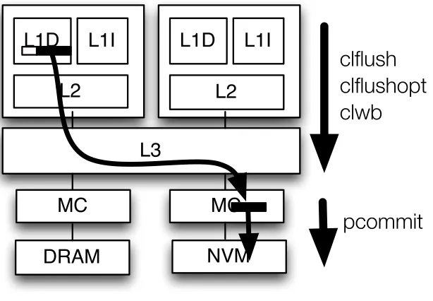
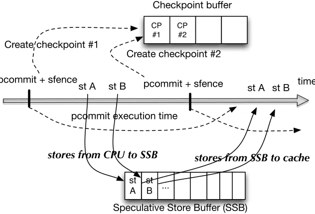
Various persistency models have been proposed[Pel14; Con09; Jos15; Int16d; Lu14], including the use of transactions[Kol16b; Vol11]. Our starting point is Intel PMEM[Int16d], a persistency model supported by several new instructions, such asclwb,clflushopt, andpcommit, used in conjunction with existing x86 instructions such asclflushandsfence.Clflushoptandclwbforce dirty data out of the cache hierarchy, whilepcommitacts as a persist barrier by forcing a flush of the write buffers in the memory controller. These instructions may be re-ordered by the processor with respect to non-dependent loads and stores, hence fence instructions are needed to precisely control when data is made durable at the NVMM. While these instructions have been announced, their performance impact has not been studied or characterized in the context of NVM workloads, and few workloads have been written using these new instructions. Similarly, ARM has recently introduced a new instruction, DC CVAP, for persistence support in ARMv8.2[ARM16].
long latencies, and incur a significant performance penalty, causing execution time overheads of up to 55%, and 21% on average, on top of logging overheads. The performance penalty arises primarily due to the pipeline stalling for the completion of thesfence-pcommit-sfenceinstruction sequence.
Based on these observations, we proposespeculative persistence(SP), architectural support to speculatively execute past long latency persist barriers to hide their latency and reduce their impact on performance. Speculative execution is triggered when a persist barrier stalls the pipeline. The analysis of our benchmarks shows that such barriers can take 100s to 1000s of cycles to complete. Rather than waiting, in SP, a checkpoint is taken at the persist barrier, the sfence is speculatively retired, and the processor proceeds speculatively retiring the sfence and following instructions. Meanwhile, the pcommit completes non-speculatively in the background. Stores are buffered and not allowed to propagate to memory until the pcommit finishes and speculation completes. Buffer-ing of speculative state and conflict detection proceed in much the same way as prior speculation schemes.
In the past, speculative execution has been proposed for other purposes such as hiding L2 miss latency[Cez06; Mut03; Kir05; Sri04], improving memory consistency model performance, and speculating past synchronization operations[MT02; RG01; HM93]. While bearing some similarities with prior speculation techniques, SP faces new challenges. First, other persist barriers are likely to occur in the shadow of the current speculative persist barrier. Because these instructions may need to flush data out of the cache, they cannot execute as part of the speculative region and must instead be buffered and played back at commit of the speculative region. Second, because some instructions must be delayed and played back later, this limits how far we can speculate. To overcome these challenges, we design multiple checkpoints to speculate across multiple persist barriers. The speculative regions commit sequentially as each pending persist barrier completes in sequence, thereby ensuring proper transactional semantics.
We evaluate our new architecture and compared it against the same system without speculation. Our experiments show that SP reduces the execution time overheads to only 4.5% on average, compared to code with logging but without PMEM instructions.
1.3
Software supported hardware logging on NVMM
As we have introduced in earlier section, one persistency model that is easier for programmers to achieve failure safety is that ofdurable transactions [Kol16b; Vol11; Int16d]. With a durable transaction, all stores in a transaction persist or none of them do.1 This is a simple and useful abstraction for programmers.
1Note a fundamental difference between durable transaction and transactional memory (TM): a durable transaction
Proteus
(NEW)
Atom
Mnemosyne
Nv-Heap
PMEM
LOW
HIGH
HIGH
LOW
FLEXIBILITY
PER
F
O
R
MAN
C
E
Figure 1.1Logging model taxonomy
In chapter 4, we explore a key challenge of using durable transactions: how to perform logging efficiently and flexibly. Durable transactions require logging, either throughredoorundologging. The log allows the transaction to be recovered if a failure occurs during the transaction. A log can be created through software code inserted by the programmer, through a library[Int16d], or directly in hardware without additional code[Jos17]. Software approaches (SW) incur large performance overheads due to additional instructions but offer the greatest flexibility, including unlimited transaction size and control over logging operations. The latter approach (HW)[Jos17] has low performance overheads, but it is typically less flexible.
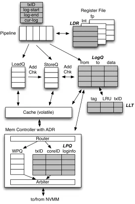
In this paper, we propose a new logging approach, referred to asProteus, that achieves the favorable characteristics of both software and hardware approaches: software controls it’s own log space, it can support unlimited transactions of arbitrary size, it can manage its own recovery, and it has low overhead. Our approach introduces two new instructions that indicate whether a load instruction should create a log entry and a log flush instruction to write the log entry to NVM. We presume no additional programming effort beyond specifying transaction boundaries, since the compiler can generate instructions appropriately for code inside transactions. Additional hardware support is introduced, largely within the core, to manage the execution of these instructions and critical ordering requirements between logging operations and updates to data to ensure durable transaction semantics.Proteusavoids any limitation on the size or number of transactions through judicious design of the interface: software remains in control of allocating the log space, and hard-ware keeps the cost of updating the log low. The taxonomy in Table 1.1 illustrates each logging model’s pros and cons.
The presence of a battery-backed WPQ is consequential: it presents a new opportunity to avoid writes to the NVMM. A key observation that we exploit is that most logs are created and discarded, because failures are rare. Thus, we apply an optimization where we distinguish data blocks in the WPQ that are there for logging or not. This distinction allows us to treat them differently, where log blocks are kept as long as possible in the WPQ and discarded when a transaction commits, whereas non-log blocks are allowed to drain from the WPQ to the NVMM. Not only does this optimization improve performance, but more importantly, it helps in extending the lifespan of NVMM by avoiding many writes to the NVMM.
We implementedProteuson a cycle accurate simulator, MarssX86, and compared it against state-of-the-art hardware logging (ATOM[Jos17]) and a software only approach. Our experiments show thatProteusimproves performance by 1.48×, on average, compared to a system without hardware logging and 10.5% faster than ATOM. A significant advantage of our approach is dropping writes to the log when they are not needed. On average, ATOM makes 2.11×more writes to memory. Even though stores are often not on the critical path, persistent writes are critical given the store-ordering constraints required for durable transactions.
1.4
Scheduling Page Table Walks for Irregular GPU Applications
GPUs have emerged as a first-class computing platform. The massive data parallelism of GPUs had first been leveraged by highly-structured parallel tasks such as matrix multiplications. However, GPUs have more recently found use across a broader range of application such as graph analytics, deep learning, weather modeling, data analytics, computer-aided-design, oil and gas exploration, medical imaging, and computational finance[NVI16]. Memory accesses from many of these emerging applications demonstrate a larger degree ofirregularity– accesses are less structured and are often data dependent. Consequently, they show low spatial locality[Cha14b; Bur12; Men10].
Tar09; Wan15a; Wan15]and multiple virtual-to-physical address translations (when accesses fall on distinct pages)[Ves16; Pic14].
A recent study on real hardware demonstrated that such divergent memory accesses can slow down an irregular GPU application by up to 3.7-4×due to address translation overheads alone[Ves16]. The study found that the negative impact of divergence could be greater on address translation than on the caches. Compared to one memory access on a cache miss, a miss in the TLB2triggers a page table walk that could take up to four sequential memory accesses in the prevalent x86-64 or ARM architectures. Further, cache accesses cannot start until the corresponding address translation completes as modern GPUs tend to employ physical caches.
In this work, we explore ways to reduce address translation overheads of irregular GPU applica-tions. While previous studies in this domain primarily focused on the design of TLBs, page table walkers, and page walk caches[LP14; Aus18; Pic14], we show that theorder in which page table walk requests are servicedis also critical. We demonstrate that better scheduling of page table walks can speed up applications by 30% over a baseline first-come-first-serve (FCFS) approach. In contrast, naive random scheduling can slow applications down by 26%, underscoring the need of agood schedule for page table walks.
We observe that page walk scheduling is particularly important for a GPU’s SIMT execution. An irregular application with divergent memory accesses can generate multiple uncoalesced address translation requests while executing a single SIMD memory instruction. For a typical 32-64 wide wavefront, execution of a single SIMD memory instruction by a wavefront can generate between 1 to 32 or 64 address translation requests. Due to the lack of sufficient spatial locality in such irregular applications, these requests often miss in TLBs, each generating a page table walk request. Furthermore, servicing a page table walk requires anything between one to four sequential memory accesses. Consequently, servicing address translation needs of a single SIMD memory instruction can require between 0 to 256 memory accesses. In the presence of such a wide variance in the amount ofwork(quantified by the number of memory accesses) required to complete address translation for an instruction, we propose a SIMT-aware page walk scheduler that prioritizes walk requests from instructions that would require less work. This aids forward progress by allowing wavefronts with less address translation traffic to complete faster.
Further, page walk requests generated by a single SIMD instruction often get interleaved with re-quests from other concurrently executing instructions. Interleaving occurs as multiple independent streams of requests percolate through a shared TLB hierarchy. However, in a GPU’s SIMT execution model, it does not help a SIMD instruction to make progress if only a subset of its page walk requests is serviced. Therefore, servicing page walk requests in a simple first-come-first-serve (FCFS) order can impede the progress of wavefronts. Our proposed scheduler thus alsobatchesrequests from
2Translation Lookaside Buffer or TLB is a cache of address translation entries. A hit in the TLB is fast, but a miss triggers
the same SIMD instruction for them to be serviced temporally together. The SIMT-aware scheduler speeds up a set of irregular GPU applications by 30%, on average, over FCFS.
To summarize, we make two key contributions:
• We demonstrate thatthe orderof servicing page table walks significantly impacts the address translation overhead experienced by irregular GPU applications.
• We then propose a SIMT-aware page table walk scheduler that speeds up applications by up to 41%.
1.5
Thesis layout
CHAPTER
2
DENSE FOOTPRINT CACHE:
CAPACITY-EFFICIENT DIE-STACKED
DRAM LAST LEVEL CACHE
In Chapter 2 we propose our new last level cache design using stacked DRAM. This chapter is organized as follows. Section 2.1 discusses related work, Section 2.2 overviews the DFC, Section 2.3 presents DFC design details, and Section 2.4 describes the evaluation methodology. At last, Sec-tion 2.5 and 2.6 discuss evaluaSec-tion results and key findings.
2.1
Related Work
Researchers have recognized the usefulness of stacked DRAM for a long time. Several earlier stud-ies demonstrated the high bandwidth benefit of using stacked DRAM as the entire main mem-ory[Woo10; Kgi06; Liu05; Loh08]. More recent studies recognize that off-chip DRAM will exist alongside stacked DRAM, hence they have proposed to use the stack DRAM as a part of the main memory[Mes15; Don10]. Concurrently, other studies explored the design and usefulness of using the stacked DRAM as a hardware managed last level cache (LLC)[Jev13; Jia10; Loh09; LH11; QL12; Zha07; Jev14; Cho15; Lee15; Gul14].
used for the tag array of the LLC is substantial and thus needs to be reduced[Jia10]. In one approach, tags are co-located in the stacked DRAM together with data (LHcache[LH11], Alloy cache[QL12], Unison cache[Jev14], and Bi-modal cache[Gul14]). As discussed earlier, while it completely solves the tag array overhead problem, this approach increases latency and bandwidth significantly, as a typical cache access requires three (rather than one) DRAM accesses: one to read out the tag, another to read out data, and another to update the state and LRU bits. To reduce such a high hit latency, Unison and Bi-modal cache rely on way predictions[Jev14; Gul14]. However, a cache miss (or way prediction miss) still require multiple times DRAM accesses, and when coupled with high cache miss rates in LLC, the performance overhead is still considerable[Jev14]. In[Jev14], the authors reported that Footprint cache as showing better performance than Unison cache when the DRAM LLC, unless the LLC is very large (1GB or larger). There is also a proposal to reduce bandwidth overheads in these cache designs at the expense of lower hit rates[Cho15].
The second approach is to rely on large block sizes, such as the 1KB Mblock size in the Intel Haswell 128MB L4 cache[Ham14]. The main drawback of using a large Mblock is bandwidth con-sumption due to insufficient spatial locality in most programs, where only a fraction of the bytes in an Mblock is actually used by the processor. To mitigate that, CHOP[Jia10]uses a "hot page" filter to avoid allocating cold Mblocks from being allocated in the LLC. Another solution, used in Footprint cache[Jev13]and Unison cache[Jev14], subdivides the Mblock into blocks and only brings blocks that are predicted useful into the LLC[Jev13]. Blocks that are not brought in are left empty (holes). Footprint cache[Jev13]is the closest related work to this paper. In contrast to Footprint cache, our proposalDense footprint cache(DFC) eliminates holes by storing valid blocks contiguously. This improves the usage of cache capacity. As a result, although virtually an Mblock size is 2KB, its physical size in the stacked DRAM LLC is variable. In a way, DFC is a compressed form of Footprint cache. With the same DRAM budget, DFC achieves the performance comparable to twice the size of Footprint cache.
2.2
Overview
As discussed earlier, the tag array overhead is a major cost of stacked DRAM LLC. One important requirement for the tag array is that it must be accessible at a low latency in order to facilitate quick determination of LLC hit or miss. This is one of the primary reasons why the tag array of the LLC is implemented in SRAM in the Intel Haswell system[Ham14]. In most stacked DRAM products, such as the Hybrid Memory Cube (HMC), the stacked DRAM access latency is only slightly faster than the off-chip DRAM access latency, primarily because design choices were made to prioritize density over fast access time in both cases. A solution is to increase the cache block size so that it reduces the number of blocks to keep track and makes SRAM tag array is viable. There is a limit to this approach, however. If the LLC is very huge, e.g. 1GB or larger, the required SRAM budget for the tag array is going to be too large. However, we believe that diminishing return from cache capacity will likely cap the LLC capacity much below 1GB, leaving the remainder of the stacked DRAM capacity as a part of the main memory to avoid duplicating not useful data in cache and main memory.
In the Footprint cache, an Mblock size of several KBs is used (e.g. 2KB). Each 2KB Mblock is divided into 32×64-byte blocks. Figure 2.1(a) illustrates a Footprint cache. The cache has a SRAM tag array and DRAM data array. The tag array shows which blocks in an Mblock are valid (represented by ‘1’s), and which ones are holes (represented by ‘0’s). Correspondingly, the data array shows valid blocks as solid-colored cells and holes as crossed-out cells. The figure shows 4 Mblocks: A, B, C, and D.
Suppose that a request comes from the processor or L1/L2/L3 cache (Step 1). After checking the tag array, suppose that the block is found on Mblock A, as indicated by the valid bit vector. Each bit in the valid bit vector represents whether the block is valid or is a hole in the Mblock. In this example, the block is then returned to the processor (Step 2a). Let us consider a different situation, where the access is to Mblock E which cannot be found in the Footprint LLC. Here we have an Mblock miss, the Footprint History Table (FHT) is looked up. The Footprint in the FHT indicates that in the past, only the first two blocks of the Mblock are accessed by the processor. Hence, only these two blocks will be fetched from the main memory (Step 3) and allocated in the LLC. An Mblock that is evicted to make room for the new Mblock updates the FHT, where the valid bits are recorded as the footprint for the evicted Mblock (Step 4). Note that as an overview, the discussion is somewhat simplified here. The actual Footprint cache uses two bits (valid and dirty) per Mblock to indicate whether an Mblock is valid or not, clean or not, and has been demanded or not. Also, the FHT is indexed using the hash of the PC of the missing load/store, and the address being missed. The Footprint cache may also be set associative.
Footprint LLC Processor +L1/ L2 Caches A 01011101 B 11001000 C 00000111 D 11110110 E 11000000 Footprint History Table (FHT) Tag Array Data Array Tag Valid Tag Footprint Step 1 Step 2a Step 2b Step 3 Step 4 Valid Hole
(a) Footprint cache.
Dense Footprint Cache (DFC)
A 0
D 0
Tag Array Data Array
Tag Start 01011001 11110110 Valid B 4 Tag Start 11001000 Valid Mblock A starts here Mblock B
starts here Hole
Mblock D starts here
cache line /DRAM row
(b) Dense footprint cache (DFC).
Figure 2.1Illustration of the Footprint cache[Jev13](a), and Dense Footprint cache (b).
but also has a starting location that indicates the offset in the cache line where the physical location of the Mblock starts. In the figure, Mblock A and B are co-located in one cache line. Mblock C and D overflow the second cache line, hence only one Mblock (i.e. Mblock D) can be kept in the cache. Note that the tag array of DFC has the same size as in Footprint cache, however the data array is half the size of Footprint cache. The total number of Mblocks that can be placed in the DFC falls somewhere between the size of Footprint cache and twice its size, depending on the average number of valid bits of Mblocks.
co-located Mblocks do not occupy the entire cache line. Note also that the holes in Footprint cache arepermanent: holes in an Mblock stay for the entire residency of the Mblock in the cache, and disappear only when the Mblock is evicted. In contrast, holes in DFC aretemporary, and can disappear when a new Mblock that can utilize the space is allocated in the cache. For example, in the figure, if a new Mblock with a size of two blocks is brought into the second cache set, the holes will disappear. Because of these two major differences in nature of holes in Footprint cache vs. DFC, there are much fewer holes in DFC, resulting in better space efficiency (fewer cache capacity misses) and better power efficiency (refreshes are applied mostly to valid data).
While the cache becomes denser, there are several unique challenges for designing a DFC. Unlike the Footprint or conventional caches, the physical size of Mblocks is different because the number of blocks that are allocated in the DFC differs across Mblocks. This introduces several new challenges to the cache placement and replacement policies. Let us consider a case where an incoming Mblock needs to be allocated in the cache. Suppose evicting an existing Mblock creates sufficient space but there are several possible Mblocks with different sizes that can be chosen. In this case, the cache replacement policy faces a similar problem to the one faced by memory management in an operating system (OS), where the requested memory size may not be equal to the sizes of blocks in the free space. Several options, such asbest fit,worst fit,first fit, orrandom fitare possible. In addition to such options, a question arises of how to incorporate traditional replacement policy information, such as stack position, when choosing which Mblock to evict.
Let us also consider a case where multiple Mblocks need to be evicted to make sufficient space for the incoming Mblock. Now we not only face the fit and stack position considerations, but we also face a plurality of stack positions to consider. For example, we may be able to evict a group of two Mblocks that have stack positions three and eight, versus a group of two Mblocks that have stack positions five and six. The first group of Mblocks contain the least recently used Mblock (stack position 8) but also a more recently used Mblock. The second group of Mblocks contain two of some of the least recently used blocks. A new placement and replacement policy is needed to choose which group of Mblocks to evict.
coverage. The following section will discuss these design issues in more detail.
2.3
Dense Footprint Cache Design
In DFC, Mblocks have different actual sizes, so we need a new cache placement/replacement policy. There are two types of cache misses in DFC: anMblock misswhere the access is to an Mblock that is not found in the cache, and ablock misswhere the access is to a block that is not found in an Mblock that is currently cached. An Mblock miss arises due to cold/capacity/conflict, while a block miss arises from inaccurate prediction of the footprint of an Mblock such that the Mblock was allocated in the cache without having the needed block. We will discuss the Mblock miss first.
While all Mblocks share the same virtual size (e.g. 2KB), their actual sizes vary and depend on how many blocks are allocated in the cache. When a large incoming Mblock needs to be allocated, we may need to evict several Mblocks to make room for the incoming Mblock. The traditional least recently used (LRU) replacement policy is not directly applicable when dealing with multiple victim Mblocks. A relevant question is: how should we take into account stack recency positions when evicting multiple Mblocks? Another question is: how should fragmentation be taken into account in the eviction? And finally: how should we handle block miss for an Mblock that is already in the cache?
2.3.1 Cache Replacement Policy
As mentioned earlier, potentially several Mblocks need to be evicted to provide space for an incoming Mblock. The first constraint that we choose is to require the evicted Mblocks to be consecutive, in order to avoid shifting the remaining Mblocks to create contiguous space large enough for the incoming Mblock. Shifting is very expensive in terms of latency and power consumption and hence we would like to avoid it.
An alternative to shifting is to split the incoming Mblock into non-contiguous parts so that it fits in the non-contiguous space freed up by evicting non-contiguous victim Mblocks. Breaking an Mblock rather than allocating it contiguously in a cache line creates unnecessary complexities in the design, as the tag array has to be designed to record multiple starting addresses. Reading from an Mblock requires assembling from non-contiguous parts, and additional computation to locate the desired block in an Mblock. Thus, we also avoid this.
A, 4
Tag Array
B, 6 C, 1 D, 7 E, 2 F, 3 G, 5 H, 0
A, 4 5
B, 6 C, 1 D, 7 E, 2 F, 3 G, 5 H, 0
3.5 4 4.5 2.5 4 2.5
A, 4 4
B, 6 C, 1 D, 7 E, 2 F, 3 G, 5 H, 0
1 1 2 2 3 0
LRU+ victim
MaxAvg victim
MaxMin victim tag stack
position 1 2
LRU+
MaxAvg
MaxMin
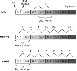
Figure 2.2Comparing three possible DFC replacement policies: LRU+, MaxAvg, and MaxMin.
the less recently used Mblock between the two neighboring Mblocks to add to the LRU Mblock. If these two Mblocks still have not freed sufficient space, we repeat the process by expanding the victim by another neighboring Mblock until the total eviction size becomes equal or larger than the requested block size. Figure 2.2 (top diagram) illustrates LRU+replacement policy. The figure shows the tag array of a cache line, showing there are 8 Mblocks currently cached in the line: A–H. Each Mblock’s LRU stack position is shown with a number indicating MRU (0), 2nd MRU (1), and so on until LRU (7). The LRU Mblock is D. Other fields, such as the starting location of an Mblock, its state, and which blocks are present, are omitted in the figure.
Now suppose that there is a miss to a new Mblock that is twice as large as any of the existing Mblocks. Thus, two Mblocks need to be evicted. With LRU+, we expand the victim group from Mblock D to its neighboring Mblock C or Mblock E. Since Mblock E is closer to the LRU (stack position 2), the two Mblocks selected for eviction are Mblocks D and E. Note, however, Mblock E is the third MRU block, hence it is risky to evict it since the processor may still need it. To reduce the risk, we propose two additional policies: MaxAvg and MaxMin.
have an average stack distances of4+26=5, a group of two Mblocks B and C have an average stack distances of6+21=3.5, etc. After these average scores are calculated, the group of Mblocks having the largest score is selected for eviction. In the figure, Mblocks A and B have the highest average score, so they are selected for eviction. Note that overall, MaxAvg is less risky as they evict Mblocks much closer to the LRU than with LRU+. The rationale for MaxAvg is straightforward: it tries to find a group of Mblocks to evict that, on average, is the least recently used group.
In the MaxMin, groups of Mblocks are scored based on their minimum stack distance positions, which is shown in the numbers above the Mblocks. For example, a group of two Mblocks A and B have a minimum score of min(4,6)=4, a group of two Mblocks B and C have a minimum score of min(6,1)=1, etc. After these minimum scores are calculated, the group of Mblocks having the largest score is selected for eviction. In the figure, Mblocks A and B have the highest minimum score, so they are selected for eviction. In this example, MaxMin selects the same Mblocks as MaxAvg for eviction.
We need to have a framework of analysis to understand the replacement policies’ behavior. For this purpose, we look several criteria. The first criteria is whether a replacement policy isself contained, meaning that it is guaranteed to be able to find a victim. If a replacement policy is self contained, it can be used alone. Otherwise, it has to rely on a different replacement policy as a backup mechanism to break a tie. The second criteria is which Mblocks a replacement policy guarantees not to evict. For example, can a replacement policy evict the MRU Mblock, second MRU Mblock, etc.? This question is important in that it helps us understand the worst case behavior of a replacement policy. An average case behavior is easy to obtain by running programs on a simulation model. However, knowing the replacement policy’s worst case behavior gives us assurance that it will not produce pathological performance cases in some situations that are not covered by existing benchmarks, as well as helps explain poor performance numbers (if any) when running benchmarks on simulation models. Let us discuss these two criteria.
The LRU+policy is self-contained, because it is always able to find an eviction victim. Starting from the LRU Mblock, it expands to one of two neighboring Mblocks with different stack positions. In contrast, MaxAvg and MaxMin are not self contained as they may produce the same replacement score for different groups of Mblocks, as shown in Figure 2.2: Mblocks C and D have the same MaxAvg score of ‘4’ as Mblocks F and G, Mblocks B and C have the same MaxMin score of ‘1’ as Mblocks E and F, etc. This means that if MaxAvg or MaxMin is deployed, we still need to use a back up mechanism to break the tie. The backup mechanism may be as simple as random, or as sophisticated as using an entirely different replacement policy.
incoming Mblock, where 1≤R<N. Furthermore, we assume that a cache line wraps around, hence Mblocks on both edges of the cache line can be considered as an eviction group, even though they are not physically contiguous. Under these constrained situations, we will analyze LRU+, MaxAvg, and MaxMin, with regard to what Mblocks are guaranteed not to be selected for eviction.
For LRU+, the following property holds:
Property 2.3.1 With LRU+, only the MRU Mblock is guaranteed not to be selected for eviction.
The reason why only the MRU Mblock is guaranteed not to be evicted is that when we need to expand the eviction group, we have two Mblocks that can be considered: the left neighbor of the LRU Mblock and the right neighbor of the LRU Mblock. If one of these neighboring Mblocks is the MRU Mblock, then it will not be included into the eviction group, because the other neighboring Mblock will be selected instead. Thus, we can conclude that in the worst case situation, no protection is provided against pathological performance behavior where really useful Mblocks such as the 2nd MRU, 3rd MRU, etc. may be evicted. If we relax the wrap-around cache line assumption, the situation becomes even worse. If the LRU Mblock is at either edge of the cache line, there is only way to expand the eviction group, and if the only neighboring Mblock is the MRU Mblock, it will be selected for eviction.
Let us now consider MaxMin. MaxMin has the following property:
Property 2.3.2 With MaxMin, thebNR−1cmost recently used Mblocks will not be selected for eviction.
For example, in a cache line that selects 2-Mblock victim out of 8 Mblocks,b8−21c=3 of the most recently used Mblocks are guaranteed not to be evicted. For a cache line containing 16 Mblocks (N=16), 7 of the most recently used Mblocks are guaranteed not to be evicted, if the Mblock group size is 2, or 5 if the group size is 3. To prove it, suppose we start with the MRU Mblock and expand it to contain groups ofRMblocks. There areRsuch possible groups, and each group will have an eviction score of 0, which is the stack position of the MRU Mblock. Next, consider the 2nd MRU block and expand it to contain groups ofRMblocks. There areR such possible groups, however some of them may overlap with the ones for the MRU Mblock. The groups that overlap with the MRU Mblock will have a score of 0, but the ones that do not overlap will have a score of 1. Thus, for the 2nd MRU, it adds to anywhere between 1 toR unique groups. If we repeat the process until the kt hMRU, we have aggregated anywhere betweenR+k−1 groups tok R groups with the lowest eviction scores. As long as the number of these groups is smaller thanN, then there is at least one group that has a higher eviction score. In other words, we need to satisfy the inequalityk R≤N−1, equivalent tok≤NR−1.
almost half of the most recently used Mblocks from being evicted if the Mblock eviction group size is 2.
Let us now consider MaxAvg. Proving a property with MaxAvg is much more challenging mathe-matically. However, we can still infer a property of MaxAvg:
Property 2.3.3 With MaxAvg, only the MRU Mblock is guaranteed not to be evicted when R =2, no guarantee otherwise.
To sketch a proof, we start by noticing that the average score for Mblock group itself averages to a constant. Suppose that the LRU stack positions of N Mblocks area1,a2, . . . ,aN, where eachaimay
range from 0 (MRU) toN −1 (LRU) for alli’s. There are exactlyN potential Mblock group that can be selected for eviction: (a1,a2, . . .aR), (a2,a3, . . .aR+1), . . ., (aN,a1, . . .aR−1). Each of these Mblock group has an average eviction score ofR1(a1+a2+. . .aR),R1(a2+a3+. . .aR+1), . . .,R1(aN+a1+. . .aR−1). The average of the eviction scores of Mblock groups turns out to be quite simple:R
P ai
R N = P
ai
N =N2−1. From here, it follows that any average score that is equal to or larger than N2−1may become an eviction victim. Is it possible to arrangeai’s such that all Mblock groups have an equal eviction
score? It turns out it is not possible, as we are dealing with LRU scores that are whole numbers. The smallest difference in eviction score between two adjacent Mblock group is provably R1. This means that in order for an Mblock group to be selected as a victim, its eviction score must be at least equal toN2−1+R1, thethreshold eviction score.
In the special case whereR=2, the threshold eviction score simplifies toN2. To prove that the MRU Mblock will never be evicted whenR=2, consider that even when the MRU Mblock (LRU score of 0) neighbors the LRU Mblock (scoreN−1), the eviction score of the MRU and LRU Mblocks isN2−1, which is less than the threshold eviction score ofN2. Hence, the MRU Mblock is guaranteed to never be evicted. With regard to the 2nd MRU Mblock, its eviction score of 1, when it neighbors the LRU Mblock, the group eviction score isN2, which meets the threshold eviction score. Thus, the 2nd MRU Mblock may be evicted.
For cases whereR >2, even the MRU Mblock may get evicted. For example, let us consider N =8,R=3. The MRU Mblock, when it neighbors the LRU (LRU score 7) and 2nd LRU Mblock (LRU score 6), their average eviction score is 413, which is larger than the threshold eviction score of
8−1 2 +
1
3=3.83.
Overall, in the worst case, the MaxAvg and LRU+provide weak protection from evicting the recently used Mblocks. In contrast, MaxMin provides the strongest protection, since several MRU Mblocks will not be evicted, depending onN andR.
2.3.2 Placement Fit Policy
can use traditional memory allocation policies such as best fit and worst fit. However, unlike the memory allocation problem, the size of free space depends on the size of victim Mblocks chosen by replacement policy. Thus, in many cases the placement fit policy is only usable for breaking the tie between several victim Mblock groups with the same replacement scores.
2.3.3 Dealing with Block Miss
Besides of the placement/replacement policy required when we have an Mblock miss, there is another type of DFP cache miss: a block miss. This is a situation where the Mblock being accessed is found in the DFP cache, but the block being accessed is not present in the Mblock. This situation occurs when an Mblock access pattern changes that the block is not anticipated by the footprint predictor. The footprint predictor predicts blocks that are useful based on the Mblock’s access pattern in the past. However, when the access pattern of the Mblock changes, the processor may access a block that was not accessed in the past and a block miss occurs.
When there is a block miss, the block must be inserted into the Mblock. How this insertion is handled depends on whether there is a hole to accommodate the new block or not. Depending on the location of the block insertion, there are several cases to consider. A hole may be there from fragmentation created by a previous Mblock allocation. For example, if a three-block Mblock was evicted to make room for a two-block Mblock, then a hole is created in its place. Figure 2.3 (top diagram) illustrates the case where there is a hole to accommodate the block. The figure shows two Mblocks (E and F), each having three blocks, co-located on a single cache line. There are two holes in the cache line, one between the two Mblocks. Suppose that the last block in Mblock E is accessed and is missed. In this case, the Mblock E reclaims the hole, and expands to accommodate the new block. The valid bits are updated accordingly.
Figure 2.3 (middle diagram) depicts a different case involving Mblocks G and H. In this case, there is no hole for the Mblock G to expand, hence, Mblock H needs to be removed and re-inserted at a different location to make room for the new block. The valid bits of Mblock G and the starting position of Mblock H are updated accordingly. This case is more expensive than the first one, since re-insertion requires reading a large number of bytes from a row for one block miss and writing them back to the row when the row is closed. However, we found that it does not happen often due to high footprint predictor’s accuracy. Furthermore, the overhead itself is very minor because it is overlapped with the miss latency; hence there is no critical-path delay. Likewise, if the block being missed is in the middle of the Mblock, the entire Mblock is removed and then re-inserted.
E 0
Tag Array Data Array
Tag Start 01011000 Valid F 4 Tag Start 11001000 Valid Incoming block
E 0 01011001 F 4 11001000
block allocated here
G 0 Tag Array Tag Start 01011010 Valid H 4 Tag Start 11001000 Valid
G 0 01011011 H 5 11001000
block allocated here
H's new location H is removed and re-inserted I 0 Tag Array Tag Start 01011010 Valid J 4 Tag Start 11101000 Valid
I 0 01011011 J 00000000
block allocated here
J is evicted, creating holes Incoming block Incoming block Case 1: Case 2: Case 3:
Figure 2.3Block miss handling in DFC.
and this situation can be handled as if there is an Mblock miss. This case is potentially the most costly because it results in an Mblock being evicted. However, to avoid the complexity and latency for handling a full Mblock miss, and counting on the low number of occurrences of this case, we simply choose to evict the Mblock that gets in the way for the Mblock that needs to expand.
2.3.4 Early Footprint Update
address (spatial offset) and program counter. Using the PC and spatial offset helps in getting a footprint prediction for highly reused code that works on different data items yet exhibiting the same access pattern. Some examples of such a scenario includes database scan and join operations[Jev13].
In the Footprint cache and our basic DFC design, the footprint of an Mblock is updated when the Mblock is evicted from the cache. Blocks that were accessed during the Mblock’s residency in the DFC became the footprint for the Mblock, causing them to be fetched the next time the cache misses on the Mblock. However, if the cache size grows, Mblocks stay longer in the cache and are evicted less frequently, which delays or even avoids footprint updates. This slows down learning for the footprint predictor, and reduces its prediction coverage. Especially, if we consider a scenario where data access pattern due to code reuse is applied over a large data set, this slow footprint learning reduces the opportunities for making footprint prediction. To overcome this slow footprint learning, we proposeearly footprint update(EFU), which allows footprints to be updated even when an Mblock is not evicted from the cache yet. One naive way to update the footprint prediction is whenever there is a new block that is accessed in the Mblock. However, this will result in too frequent footprint table updates, which increases occupancy and power consumption of the FHT. Furthermore, updating the FHT too soon is risky because incomplete footprints reduces footprint prediction accuracy. Thus, we should design footprint update criteria that is not too aggressive and yet still allow early updates.
To achieve that goal, the criteria for an early update that we use is the number of accessed blocks in an Mblock during its residency in the DFC. Over time, during an Mblock’s residency in the cache, more and more of its blocks are accessed. Once the number of blocks accessed reaches a threshold, the footprint is updated. We refer to this as Early Footprint Update (EFU). This allows the footprint predictor to learn footprints early, increasing the footprint prediction coverage. However, the footprint predictor is possibly updated using incomplete access pattern information, hence EFU trades off accuracy for coverage. As long as the benefit from increased coverage outweighs the drawback from reduced accuracy, EFU improves performance. Through evaluation, we found that using multiple threshold values works well. For example, we may have threshold values of 16, 24, and 32. When the number of accessed blocks reaches 16 for an Mblock, we update the footprint predictor. Later, when the number of accessed blocks reaches 24, we re-update the footprint predictor, etc.
2.3.5 Overhead analysis
masking logic is roughly less than 0.6 ns. We believe that such logic is probably going to cost way less than half nanosecond if we consider the technology scaling. Thus, a cache block look up overhead is negligible.
While the replacement policies discussed here are more complex than a regular LRU, fortunately it is only used for the LLC which is much less frequently accessed than other cache levels. Moreover, the victim selection itself will be very fast, because all operations can be performed in parallel. The victim selection starts with making victim Mblock groups, where all victim Mblock groups can be made in one time SRAM access in parallel with a few additions and comparisons in case of MaxMin and LRU+. Later on, looking up the victim among groups can be executed in parallel as well, then the smallest group satisfying the incoming macro block size is selected. Thus, only one time SRAM access to every macro block tag in the set will be dominant time and all other operations are processed in parallel. Furthermore, the replacement policy computation can be overlapped with the LLC miss latency, so that it does not generate any critical-path delay.
2.4
Methodology
For evaluating DFC, we primarily target scale-out memory intensive server applications/benchmarks from CloudSuite 2.0[Fer12], including Data Analytics (DA), Data Caching (DC), Data Serving (DS), Software Testing (ST), Web Search (WS), and Graph Analysis (GA). All these benchmarks are run on a Simics 3.0.31 virtual machine with AMD64 CPU and 16GB main memory, running Linux OS Ubuntu 10. We run each server benchmark for about a few hours until each server benchmark enters the phase of processing client’s requests. Then, we use 3 billlion memory instructions to produce a trace. In the simulation, 2 billion memory instructions are used to warm up the cache structures and 1 billion memory instructions are used for detailed simulation. The trace is designed to be sufficiently comprehensive to enable timing and power simulation. It contains basic information such as the memory instruction type, program counter, and address. The trace also contains dependence infor-mation between memory instructions, the number of non-memory instructions separating two memory instructions broken into ones (directly or indirectly) dependent on the preceding memory instruction and ones that are independent.
We envision a 16-core system with SRAM L1 and L2 caches private to each core, and a stacked DRAM L3 cache shared by all cores. Since our trace was collected from a single core, we assume the L3 cache to be partitioned among all cores equally, and simulate just one core and one partition of the L3 cache. The main memory is assumed to be off-chip DRAM. DRAM parameters for both the L3 cache and the off-chip DRAMs are shown in the table.
Table 2.1The baseline system configuration.
Processor 16 cores
3.2GHz, 1 IPC
L1 I$ and D$ 32KB, 4-ways, 64B Block
2 cycles each
L2 cache Variable size and latency (Table ??)
Off-chip DRAM 16GB, DDR3-1600 (800MHz), 1 channel
8 Banks per rank, 16KB row-buffer
Stacked DRAM
DDR-like interface (1600MHz), 4 channels 16 Banks per rank, 8KB row-buffer
128 bits per channel
tCAS-tRCD-tRP-tRAS-tRC 11-11-11-28-39
tWR-tWTR-tRTP-tRRD-tFAW 12-6-6-5-24
For the DRAM L3 (LLC) cache, we implement six different schemes: Footprint cache[Jev13], Unison cache[Jev14], block-based DRAM cache (i.e. DRAM cache with a traditional 64-byte block size), an oracle DRAM cache that always hit and has no tag space overheads, our scheme DFC, and for comparison purpose, no L3 cache. For Footprint cache and Unison cache, we follow the optimized parameters from[Jev14], where the cache is 4-way set associative, each DRAM row is 8KB, each Mblock is 2KB for Footprint cache, and each Mblock is 960B for Unison cache. For DFC, we implement a design with 8KB DRAM row which can hold anywhere from four Mblocks to eight Mblocks.
Table 2.2L2 cache size configurations as affected by a limited SRAM budget.
LLC size (MB) 32 64 128 256 512
Unison
L2 Size (MB) 16 16 16 16 16
Latency (cycles) 13 13 13 13 13
Footprint
L2 Size (MB) 15.80 15.59 15.22 14.45 12.94
Latency (cycles) 13 13 13 12 11
DFC
L2 Size (MB) 15.58 15.16 14.34 12.73 9.55
Latency (cycles) 13 13 12 11 10
64B Based
L2 Size (MB) 13.94 12 8.25 1 None
Latency (cycles) 11 11 10 9 None
2.5
Evaluation
2.5.1 Overall Performance
Figure 2.4 shows the speedup ratio of Footprint cache (Footprint), Unison cache (Unison), our design (DFC with MaxMin), and 64-byte block size cache (64B block), when the L3 cache capacity per core is 64B (part (a)) or 256MB (part (b)). For reference, an oracle L3 cache with zero miss rate and zero tag overheads (Full Stacked DRAM) is also added to both figures. The speedups are relative to a baseline of a system with only off-chip DRAM.
0.8
0.9
1
1.1
1.2
1.3
1.4
DA
DC
GA
ST
DS
WS Gmean
Speedup
Footprint Unison DFC 64B block Oracle
(a) 64MB L3 cache partition per core.
0.8
0.9
1
1.1
1.2
1.3
1.4
DA
DC
GA
ST
DS
WS Gmean
Speedup
Footprint Unison DFC 64B block Oracle
(b) 256MB L3 cache partition per core.
Figure 2.4Speedup ratios of Footprint cache (Footprint), Unison (Unison), our design (DFC), and small-block cache (64B block), for when the L3 cache size is 64MB (a) or 256MB (b), relative to system with no stacked DRAM L3 cache. Full Stacked DRAM is an oracle L3 cache with zero miss rate and zero tag overheads.
In contrast to the Footprint cache, DFC has no internal fragmentation. However, DFC may incur some external fragmentation when there are holes in a cache line that are not sufficiently large to an additional Mblock. 64-byte block cache has no fragmentation whatsoever, so it slightly outperforms DFC in few benchmarks (ST, DS, and WS). However, DFC outperforms 64-byte block cache overall (9.4% vs. 8.8% gmean). Both significantly outperform the Footprint cache because of their efficient use of L3 cache capacity.