DESIGN, ANALYSIS AND SHAPE OPTIMISATION OF METALLIC
BELLOWS FOR NUCLEAR VALVE APPLICATIONS
A.K. Dureja1, M.K. Sapra1, R.P. Pandey2, P. Chellapandi2, B.S.V.G.Sharma1, J.N.Kayal1, S.C. Chetal2, R.K.Sinha1
1Reactor Design & Development Group, Bhabha Atomic Research Centre, Trombay, Mumbai, INDIA-400085 2Reactor Engineering Group, Indira Gandhi Centre for Atomic Research, Kalpakkam, INDIA-603102
E-mail of corresponding author: [email protected]
ABSTRACT
Bellows are thin, flexible shell structures and are widely used in the industry for accommodating thermal expansion and for sealing purpose. These are generally made of thin metallic sheets by hydro-forming etc. They can very well perform under high pressure and temperature conditions. Structural integrity of these components is very important from the point of view of overall reliability of the system. These are widely used in the valves to provide stem travel and seal with zero leakage. Hot Shutdown Passive Valves (HSPVs) are planned to be used in Advanced Heavy Water Reactor (AHWR) to maintain steam drum pressure in a passive manner. In HSPVs, bellows are planned to be used as an actuating as well as sealing device. Bellows are generally designed based on guidelines given by Expansion Joint Manufacturer Association (EJMA). However, EJMA only supports standard U-shaped/Toroidal bellows. In the nuclear industry, we face stringent requirements of high pressure and large displacement to match reactor condition. High pressure requires large thickness but it introduces high axial stiffness, which is not desirable. For this diverse requirement, we need to optimize its shape as well as multiply construction to reduce the level of stresses generated. The level of stresses and strains govern fatigue life of these bellows.
The paper describes the basic sizing of the bellows using EJMA guidelines based on the design requirements. For HSPV, bellows of stainless steel grade 304L material needs six plies of 0.5 mm thickness due to process pressure requirement. But this introduces very high axial stiffness and does not meet the intended travel requirement of the valve. Later the material of construction was changed to INCONEL-600 and was found to be satisfying both the requirements of stresses as well as axial stiffness with two plies of 0.5 mm thickness. The bellows’ design was evaluated using finite element method based package, CAST3M (A FE code developed by French nuclear agency, CEA). A parametric finite element model was developed to quickly incorporate any change in the design stage. A methodology was evolved to compute membrane and bending stresses from component stresses resulting from finite element model. This procedure was validated using published data too. Bellows’ shape plays major role in development of membrane and bending stresses in the component. Various shapes were modeled, analysed and found that omega shaped bellows with different lobe radii outperforms the conventional U shaped bellows. Based on the above studies, omega shaped bellows of two sizes in sufficient numbers were procured from reputed suppliers to put them under cyclic test and to estimate its fatigue life.
NOMENCLATURE
b
D
Inside diameter of bellows convolutionsS
4 Bellows meridional bending stress due to pressurem
D
Mean diameter of bellows convolutionsS
5 Bellows meridional membrane stress due to displacementQDT
Non-dimensional parameter =p
m
t
D
q
×
2
.
2
S
6 Bellows meridional bending stress due to displacementQW
Non-dimensional parameter =w
q
2
q
Convolution pitch2
S
Bellows circumferential membrane stress due to pressuret
pBellows’ material thickness for one ply
3
INTRODUCTION
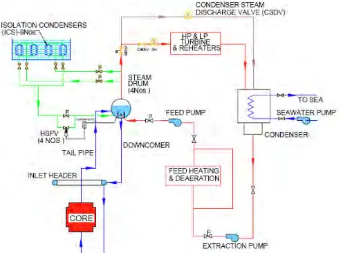
AHWR is being designed and developed by India to achieve large scale use of thorium for the generation of nuclear power [1]. AHWR is a 300 MWe vertical pressure tube type boiling light water cooled and heavy water moderated reactor. The reactor system consists of several passive safety features working on natural laws. Working of these passive safety features are aided by self actuating devices. The most important function of the Main Heat Transport (MHT) system of AHWR is to remove the nuclear heat form the core of the reactor using natural convection under reactor operating and shutdown condition. HSPVs are provided in AHWR to maintain steam drum pressure under station black out (SBO) condition. Under this condition, steam pressure in the MHT system keeps increasing due to decay heat. Increase of system pressure, beyond a set value, opens the valve proportionately and thereby limits the system pressure [2]. Location of HSPVs in MHT system of AHWR is shown in Fig. 1.
Fig. 1: Location of HSPV in MHT system of AHWR
Metallic bellows have been widely adopted as gland seals in nuclear valves. It is fabricated as thin-walled continuous metal shells with deep convolutions, generally axisymmetric. Bellows can be designed to withstand specified pressures and accommodate valve stem displacements. The nuclear industry, with its stringent quality and performance requirements, is partly responsible for development of bellows valves [3]. In its early years, the nuclear industry experienced unacceptably high loss of coolant and moderator from leakage or components’ failures. Conventionally sealed valves as well as mechanical joints and pumps were among the components responsible mainly for these losses. Coolant and moderator leak/loss contribute to radiation spread, significant reduction in operating performance and high cost of maintenance. Hence, it was essential that the performance of these components be improved to eradicate these problems. Confronted with this urgent situation, engineers and researchers were forced to find immediate alternative solutions to eliminate leakage along valve stems, in the design stage of nuclear valves. In view of the above, bellows seals as gland packing were adopted in nuclear valves. Apart from nuclear valves, metallic bellows are also being used in expansion joints in order to control thermal expansion/contraction in pipelines and pressure vessels. Its design needs optimisation because these components must compromise between two contradictory conditions.
1) Bellows wall thickness must be large enough to resist the internal/external pressure. 2) Bellows wall thickness must not be too large to limit the desired flexibility.
Bellows are generally designed based on guidelines given by EJMA [4]. However, EJMA only supports standard U/toroidal-shaped bellows. In the nuclear industry, we face stringent requirements of high pressure and large displacements to match reactor-operating conditions. For this diverse requirement, we need to optimize its shape as well as multiply construction to reduce the level of stresses generated.
BASIC DESIGNING
withstand internal/external pressure, while at the sametime providing the required flexibility (the ability to absorb movement). These deflections are typically in the form of axial deflection andbending rotation, and in some cases lateraldisplacement of the ends.
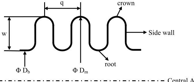
Fig. 2: U-Shaped Bellows’ Geometry
Bellows are generally manufactured with a much thinner wall than the cylindrical shells to which they are attached (required to provide the necessary flexibility). However, they are provided with sufficient metal area to resist the circumferential force due to internal (or external)pressure by forming the wall into convolutions. Where this does not provide sufficient metal wall area, reinforcing rings are added, usually on the outside of the bellows in the root locations under internal pressure loading, in order to provide additional resistance to pressure induced rupture (burst failure). Bellows are subjected to circumferential and meridional membrane and bending stresses due to internal (or external) pressure and imposed displacement.
The bellows’ convolutions have planar symmetry with planes normal to the bellows axiscutting through the root and crown apexes. Due to this symmetry, the roots and crowns can be visualized as points of fixed meridional bending restraint. The portion between bellows’ curve and side walls can be envisioned as a curved beam with fixed ends. Early evaluations of bellows stresses were based on these concepts [5].
Determination of an accepted design of a bellows is tedious process because it involves numerous variables such as diameter, material thickness, convolution pitch, convolution height, number of plies, manufacturing technique and material type. Instability of bellows due to internal pressure can cause a bellows to buckle in a manner similar to a column subjected to compressive loading.
Several theoretical stress analyses of bellows have been developed, each of these has inherent limitations. The analyses are normally based on the assumptions which approximately predict behavior of a bellows. One of such analysis has been done by Anderson [6]. Design codes developed by EJMA for bellows/expansion joints are based on standard results of Anderson’s work and utilizing equilibrium consideration under pressure loading along circumferential and meridional directions. Most of the bellows are designed using equations provided in the EJMA.
Design Using EJMA
Design equations given for U-shaped bellows as per EJMA (8th edition) have been used for determining membrane and bending stresses. Selection of material is an important requirement to design a bellows. Stainless Steel (SS-304L) was chosen as bellows material for given design condition. Basic design requirements for main bellows are as mentioned in Table 1 [7].
Table 1: Basic design requirements for main bellows of HSPV for AHWR
S. No. Dimension Value S. No. Dimension Value
1. O.D. of bellows 80 mm 7. No. of plies 2/3/4
2. I.D. of bellows 60 mm 8. Ply thickness 0.5/1.0/1.5 m
3. Axial displacement 15 mm 9. External operating pressure 70 bar 4. Spring constant 150 - 170 N/m 10. External design pressure 110 bar 5. Relaxed length of bellows 375 - 425 mm 11. Operating temperature 285 ºC 6. No. of convolutions 20 - 50 12. Maximum design temperature 300 ºC
w
root
crown
q
Φ
D
mΦ
D
bThe primary concern in bellows design is meridional bending stress, since this is significantly greater than the meridional membrane stress. The ratio of the bending to membrane stress is approximately proportional to the ratio of bellows convolution depth to ply thickness. This ratio is relatively large for thin-walled bellows, making the meridional bending stress much larger than the meridional membrane stress. Since the stress criteria are relative to the sum of these two components, meridional membrane stress is relatively insignificant in bellows design. Anderson [6] gave a generalized treatment to the calculation of stresses in a U-shaped bellows. It has been shown that these equations are sufficiently accurate for design in comparison with elastic finite element analysis results [8].
A MATLAB code based on EJMA standards for U-shaped bellows was developed to calculate stresses, fatigue life and spring constant etc. Based on the inputs, stresses were calculated using EJMA standards. It was found that the requirements of number of plies made of SS-304L (each ply having thickness of 0.5 mm) are more than four and spring rate per convolution comes very high. Manufacturing constraints leads to use of limited number of plies, maximum of four for Indian manufacturers. The material of construction was changed due to this constraint and Inconel-600 was selected. Material properties of SS-304L and Inconel-600 are listed in Table 2.
Table 2: Material properties for possible materials of construction for main bellows
Material Modulus of Elasticity [GPa] Poisson’s Ratio Yield strength [MPa] Ultimate Strength [MPa]
SS-304L 175 0.3 210 515
Inconel-600 215 0.3 850 910
Stresses were calculated using EJMA standards for bellows made of Inconel-600 and it was found that requirement of number of plies (each ply having thickness 0.5 mm) reduces significantly. Consequently, spring rate also comes within desired limits. EJMA result showed that two plies made of Inconel-600 are sufficient to cater for design requirements. It shows that greater strength and high modulus of elasticity of Inconel-600 are responsible for reduction of number of plies [9]. Design of bellows using EJMA standards is not only governed by design specifications but it also depends on manufacturing constraints. It is to be noted that the fatigue life prediction using EJMA, limits the choice of material to only austenitic stainless steel. Fabrication of bellows is a tedious process and is not as conventional as other manufacturing processes. At present the manufacturing limitations pertaining to Indian industries limits the number of plies to a maximum of three for multiply bellows. Hence, proper material selection is an important parameter in design of metallic bellows.
DETAILED ANALYSIS USING FINITE ELEMENT METHOD
Detailed analysis of U-shaped metallic bellows has been carried out by finite element based computer program CAST3M [10]. Finite element modeling of the U-shaped bellows necessitated following assumptions [11]:
1) Ply thickness considered to be uniform throughout the convolution. 2) Material properties are uniform throughout the bellows.
3) Bellows’ convolutions exhibit identical behavior under load. 4) Interply interaction has not been considered
5) The initial bellows’ state is stress free i.e. residual stresses are not present.
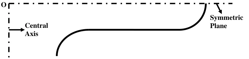
Geometry of the bellows is symmetric with respect to its central longitudinal axis. Loading pattern and boundary conditions are also symmetric in nature. Therefore, two dimensional axisymmetric finite element analysis was used to obtain the stress distribution in the bellows. Two noded axisymmetric thin shell element (COQ2) was used for finite element modeling of bellows. Only half convolution is sufficient for modeling. Two dimensional axisymmetric half convolution finite element model of the bellows is shown in Fig. 4. A linear elastic analysis of Bellows was carried out with material properties as listed in Table 2.
O
Symmetric
Plane
Central
Here external pressure causes opening of convolutions which leads to radial movement of extreme points of root and crown portion of bellows. Since half convolution of model is like curved beam with fixed ends, axial movement of these points is not possible. Hence, extreme points are location of fixed boundary condition as per axial movement is concerned.
In case of axial displacement loading, it is considered that displacement given to bellows distributed equally over number of convolution. Since FEM modeling requires half convolution for analysis, half of displacement per convolution is acting on bellows as applied displacement. Therefore in displacement loading half convolution of model is like curved beam with one end as fixed point with no axial displacement and other end having half of axial displacement per convolution [12]. Stresses calculated for axial displacement are considered as secondary stresses. Secondary stresses play role in determination of fatigue life of bellows. While stresses calculated for pressure loading are primary stresses. Therefore, pressure loading and axial displacement are considered separately. When both the loads are acting at same time, stresses are additive at some points and subtractive at some other points in bellows’ convolution symmetrically. Hence, pressure loading stresses in combination with displacement loading stresses decide the fatigue life of bellows.
FE Analysis and Results
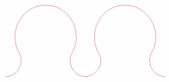
Exact solution by numerical methods such as FEM avoids the errors introduced by approximations necessary for analytical solution of the toroidshell equations. Since pressure loading and displacement loading are considered separately, separate FEM analysis was done for both the cases. On application of external pressure, bellows convolution tries to open up as shown in Fig. 5. Deformation pattern of bellows subjected to displacement loading is different from pressure external loading. Bellows convolution squeezes symmetrically with respect to crown (transverse) axis. Stresses generated due to displacement loading are significant in fatigue life calculation of bellows. Stress calculated from EJMA standards and stresses evaluated from FEM analysis for bellows made of Inconel-600 are enlisted in Table-3. Deformation pattern due to displacement loading is shown in Fig. 6.
Table 3: Stresses from EJMA and FEM for Inconel-600 Bellows
2
S
(psi)S
3(psi)S
4(psi)S
5(psi)S
6(psi)EJMA 33633 7752.1 79880 1648.2 62309
FEM 42467 21025 83400 18831 62314
The calculation of maximum bending stress due to pressure and deflection calculated by finite element analysis and by EJMA are sufficiently accurate. In deep convolution (low QW) and thin walled (high QDT) bellows, deformation of the side walls in bending due to pressure tries to displace root and crown towards the center of the convolution. The meridional membrane stresses in the side walls too tries to displace the root and crown towards the center of the convolution. Cumulative effect of membrane and bending in side walls induce high circumferential stress in the bellows’ root and crown sections. As a result of this, the circumferential membrane stress
S
2 predicted by finite element analysis deviates from the circumferential membrane stress predicted by EJMA equation [5].Meridional membrane stress,
S
3calculated by finite element analysis and that calculated using the EJMA equation also shows difference. This difference in calculated stress is due to the fact that the maximum meridional membrane stress for deep convolution and thin walled bellows does not occur at the location considered in the EJMA equation. It generally occurs, in these bellows, in the curved portions of the bellows, closer to the side walls [5]. Stresses generated in bellows are highly geometry dependent. Two non dimensional parameters QDT and QW used in EJMA decide the geometry of bellows. These parameters are responsible for differences in stresses calculated using FEM and EJMA.In present case of bellows, QDT is equal to 1.2 and QW is equal to 0.77. The location of highest meridional stress in deep convolution bellows occurs in the curved portions of the bellows, near the junction with the side walls. In these deep convolution bellows, the bellows root curve is pulled out and the bellows crown curve is pulled in by extension (and the reverse for compression). Hence, high circumferential membrane stress is present in these locations. Thus for deep convolution (low QW) and thin walled (high QDT) bellows, the maximum meridional membrane stress is higher than the stress predicted by the EJMA equations.
In view of above, as shown in table-3, the prediction of meridional bending stresses due to pressure and displacement were found to be relatively accurate. However, the prediction of membrane stress using FEM was found to be deviating significantly from the EJMA results. The accuracy of the prediction of highest meridional membrane stress could be improved by evaluating the meridional membrane stress at right locations. However, the error in calculation of meridional membrane stress due to deflection has very little practical significance in bellows design because the meridional membrane stress is substantially lower than the meridional bending stress.
SHAPE OPTIMISATION USING FEM
Design of bellows using EJMA standards and FEM Analysis of bellows revealed that stresses induced in bellows are highly geometry dependent. Large metal area of bellows shows better integrity as per circumferential and bending stresses is concern. Apart from U-shaped bellows, other shapes can also fulfill the requirements. Hence, shape optimization of bellows is essential. Bellows having large metal area also shows better stability as compare to U-shaped bellows as far as internal pressure is concerned. The optimization of shape is essential to satisfy all design specifications. In other words the optimized bellows should have sufficient metal area but not to the extent that it leads to bellows convolution’s interaction [13].
Finite element analysis carried out for omega shaped bellows for given overall dimension (Table 1) shows that bending stress and circumferential stress reduces significantly. Table 4 enlists the stresses induced in U-shaped bellows and optimized omega shaped bellows due to pressure loading.
Table 4: Pressure stresses in U-shaped and omega shaped bellows Type of Bellows
2
S
(psi)S
3 (psi)S
4 (psi) U- shaped Bellows 42467 21025 83400 Omega shaped Bellows 29463 6284.2 58386Location of highest meridional bending stress changes in omega shape bellows. Position of maximum circumferential stress and meridional stress also changes. Optimisation of bellows is essential because it must fulfill various contradictory requirements and design specifications. Various parameters like large metal area, ply thickness, number of plies, manufacturing consideration etc. affect the shape of bellows. Hence, optimization of above mentioned parameters pave a way for omega shaped bellows.
BELLOWS TESTING
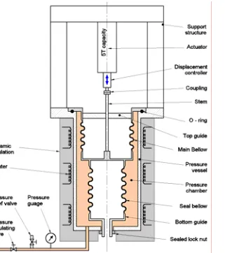
To test and qualify the bellows under simulated environment of high pressure and temperature with axial displacement,, a Bellows’ Test Facility (BTF) was built at Structural Mechanics Lab (SML), Indira Gandhi Centre for Atomic Research (IGCAR), Kalpakkam. While commissioning the test facility, displacement error of 0.2 mm and friction forces of sliding system of 50 N were observed. These values were found to be acceptable. The general arrangement of bellows assembly installed at BTF is shown in Fig. 8.
Fig. 8: Bellows’ test facility and bellows’ assembly under test
An assembly consisting of two bellows namely main and seal bellows were tested under the simulated environment. During the testing, bellows assembly was pressurized using controlled gas pressure from 10 bar to 80 bar in steps of 10 bar. Two numbers of displacement cycles, as shown in Fig. 9, each of 12 seconds (trapezoidal pattern) and 10 mm in amplitude, were applied using 5 T capacity actuator.
10 mm max.
1s 4s 2s 4s 1s = 12 seconds period
More than 75,000 such cycles have been applied so far and there is no failure observed yet. It is planned to continue the cycling test till the failure of bellows assembly to estimate bellows life cycle data. Load displacement curves on each pressure were recorded on PC based Data Acquisition System (DAS) and the area inscribed within the hysteresis curve was computed.
CONCLUSION
This investigation gives an overall appraisal of the behavior of the metallic bellows under pressure and displacement loadings. The bellows were designed using EJMA guidelines. Finite element models were developed using thin shell axisymmetric elements. Linear elastic analyses were carried out to compute stresses and displacements under designated loading conditions. The finite element stresses were compared with stresses calculated using EJMA equations. The following conclusions can be drawn from the studies conducted.
1) This work enabled us to benchmark our analysis of FEM with EJMA for design governing bending stresses. This paved a way to use FEM analysis to any generalize shape of bellows whose designs are optimized by designer for a particular design conditions.
2) The EJMA calculation of meridional bending stresses due to pressure and deflection in U-shaped bellows were found to be reasonably accurate when compared with FEM results.
3) However meridional membrane stresses are not fairly accurate and well predicted because the location where these stresses werecalculated, in the development of the EJMA equations may not always be the location of highest meridional membrane stress.
4) The maximum membrane stress due to both pressure and deflection deviate significantly from the stress predicted in the EJMA equations for deep convolutions (low QW) and thin walled bellows (high QDT). 5) Maximum meridional bending stress exists at the root, crown, and sidewall of the bellows due to pressure
loading alone.
6) The meridional membrane stress is much smaller as compared to the meridional bending stress. The bending stress is higher by a factor of ratio of convolution depth & ply thickness.
7) The stress analysis showed that the bending meridional stresses are dominant. Moreover the axial displacement is generally the loading, which controls the fatigue life.
8) Above analysis indicates that the numerical (FEM) and analytical (EJMA) results are in good agreement.
REFERENCES
[1] R.K. Sinha, A. Kakodkar, “Design and development of AHWR-the Indian thorium fuelled innovative nuclear reactor”, Nuclear Engineering and Design, Vol. 236, 2006, pp. 683-700.
[2] M.K. Sapra, S. Kundu, A.K. Pal, B.S.V.G. Sharma, “Functional and performance evaluation of 28 Bar Hot Shutdown Passive Valve (HSPV) at ITL for AHWR”, BARC report No. BARC/2007/E/003.
[3] D.F. Dixon and M. Abbas, “Prototype bellows sealed nuclear valve development- reliability through testing”, Atomic Energy of Canada Limited, Report AECL- 5972, January 1978.
[4] Standards of the EJMA association, 8th edition, 2003.
[5] Charles Becht, IV, “Behavior of bellows”. A dissertation submitted to the school of graduate studies in partial fulfillment of the requirements for the degree of Doctor of philosophy, Faculty of engineering and applied science, Memorial university of Newfoundland, May, 2000.
[6] W.F. Anderson, “Analysis of Stresses in Bellows, Part 1: Design Criteria and Test Results”, NAA-SR4527 (Pt.1), Atomics International Division of North American Aviation, 1964.
[7] A.K. Dureja, M.K. Sapra, “Design and Analysis of Bellows for prototype HSPV for AHWR”, BARC report No. BARC/RED/IS/RCCS/10-07/06.
[8] Charles Becht, IV, “An evaluation of EJMA stress calculation for unreinforced bellows”, Journal of Pressure Vessel Technology, Vol. 124/129, 2002.
[9] www.specialmetals.com [10] User manual for CAST3M, 2008.
[11] P.Janzen and H.Gentili, “Evaluation of performance of bellows for nuclear valves”, Atomic Energy of Canada Limited, Report AECL- 5975, 1978.
[12] F. Osweiller, “Design of an expansion joint by a finite element program - comparison with the EJMA standards”, PVP –Vol. 168, metallic bellows and expansion joints, 1989, pp. 87-94.