February, 22nd and 23rd, 2019
INFINITELY VARIABLE TRANSMISSION SYSTEM USING OSCILLATING
TORQUE
Ranjit Vasant Rajale (Author) Mechanical Engineering Department,
SCSMCOE ,NEPTI AHMEDNAGAR,INDIA
Raut S.D.,
Mechanical Engineering Department line 2-name of SCSMCOE ,NEPTI
AHMEDNAGAR,INDIA line 4-e-mail address if desired
Akolkar C.S (Author) Gaikwad S.P (Author) Mechanical Engineering Department, Mechanical Engineering Department,
SCSMCOE ,NEPTI SCSMCOE ,NEPTI
AHMEDNAGAR,INDIA AHMEDNAGAR,INDIA
Khilari R.R.
Mechanical Engineering Department SCSMCOE ,NEPTI AHMEDNAGAR,INDIA
Abstract—
The Infinitely Variable Transmission (IVT) system is a automatic gearbox designed to save fuel, give a smoother drive and improve performance of the vehicle. The purpose of the IVT is to allow the engine to maintain an almost constant speed. The Infinitely Variable Transmission system (IVT) is a transmission design that transmits mechanical power via oscillating torque. It is different from the traditional speed ratio methods. This infinitely variable transmission (IVT) controls the output torque its opposite from the output speed ratio. From zero torque to the full capacity of torque output it is the infinitely variable torque. it can be produced with no clutching or torque conversion required at the input in the IVT. The centrifugal forces of rotating eccentric masses is mounted on shaft to create an oscillating torque which harness the power. The function of One-way clutches is to convert the oscillating torque to a unidirectional torque. In the infinitely variable transmission (IVT) system a series of offset masses used to transmit torque to the output shaft which comes after the clutches.
Key words — Infinitely Variable Transmission (IVT), Continuously Variable Transmission (CVT), Automatic gearbox.
I. INTRODUCTION
The manual gearbox in the cars could be very
difficult for the driver while driving in the traffic.
To optimize the fuel consumption it needs to
change gears frequently. In the automatic
infinitely variable transmission eliminates the speed
gear change operations for driver and it ensures
the optimal transmission ratio. In IVT the zero
improvements in the existing design. The
Infinitely Variable Transmission system must be
able to withstand a series of tests including that
of endurance.
The moments produced by rotating offset
masses to transfer torque is utilized in the
transmission in the IVT at variable output speed,
from the engine to the
output shaft. All parts from the old IVT design and existing research areanalyzed
in detail to modify the same for reliable and efficient
IVT system.
II. PROBLEMSTATEMENT
Manual transmissions (MT) are the most common in today's cars. This transmission only allows a limited set of fixed gear ratios. The gear box is manual transmission gear box with 4 or 5 speeds. i.e., Gears 0-1-2-3-4-5, in order to shift from one gear to another one has to perform three operations i.e., De-clutching, change gear gradual engagement thus in order to reach top speed i.e., 5th gear we will have to perform 15 operations. This becomes a problem while running vehicle in dense traffic conditions The infinitely variable transmission (IVT) system is a sophisticated automatic gearbox designed to save on fuel, cut emissions, give a smoother drive and improve performance. Because most motors, whether powered by liquid fuel or electricity, have a narrow RPM range at which they operate at top efficiency, they generally
III. METHODOLOGY
February, 22nd and 23rd, 2019 The system design also determines the system
components and their shape and overall dimensions. In the phase Mechanical Design, the parts mentioned in the bill of material is designed for stress and strain under the given system of forces and appropriate dimensions are derived. The standard parts are selected from the PSG design data handbook.
For the next phase Production Drawing Preparation, Production drawings of the parts are prepared using the 3D modeling software CATIA V5. The 3D design and 2D drawings are made with the same software with appropriate dimensional and geometric tolerances. Raw material sizes for parts are also determined. In the phase Material Procurement & Process Planning, material is procured as per raw material specification and part quantity. Part process planning is done to decide the process of manufacture and appropriate machine for the same. The next phase is manufacturing, parts are produced as per the part drawings. In the phase Assembly of the IVT test rig, assembly of the device is done as per
IV. LITERATUREREVIEWONIVT
A) Giacomo Mantriota, Presented paper on Performances of a series infinitely variable transmission with type I power flow [1], In this paper it is shown the possible power flow directions of a power split CVT system. In this work the experimental results related to the measure of power flows and the efficiency of the series-IVT with type I power flow are obtained. The experimental tests were performed using a special test rig to measure the power flows in different operating conditions.
B) Giacom Mantriota, Presented paper on Performances of parallel infinitely variable transmissions with a type II power flow [2], He reported the work on experimental results obtained for a parallel-IVT prototype with type II power flow. The main goal of this work is to appraise the IVT performances in terms of torque, power flows and efficiency.
C) F.Bottiglione, S. De Pinto, and G. Mantriota, Presented paper on infinitely variable transmissions in neutral gear: Torque ratio and power re-circulation [3]. In this paper, the power recirculation and the torque ratio of infinitely variable transmissions (IVT) are investigated. The focus is on the gear neutral condition, which very useful in many applications but actually critical in terms of efficiency, reliability and control.
D) Ion ION, Presented paper on George Constantinescu’ Torque Converter Analysis by Simulink [5]. He analyzed Constantinescu Torque converter by Simulink. Modeling of the dynamics for an automotive application is demonstrates its high performance characteristics. In the modeling of this power
transmission system, the stiffness of the shaft and various control logics are included.
E) Amarsinh Shinde, Subim Khan, Presented paper on Modeling, Design and Development of Infinitely Variable transmission System [9]. Studied that the design considerations for the parts in IVT and the methodology to select the good option from various solutions. This study is based on the modeling, design and development of the infinitely variable transmission system. This study shows the methodology of part selection and analysis of critical parts made to ensure the reliability and
V. INFINITELYVARIABLETRANSMISSION(IVT) SYSTEM
The infinitely variable transmission (IVT) made for the vehicle is based on a patented design owned and developed by Terry Lester, of Fort Worth, Texas. Modifications have been made in to the design to match the requirements of the vehicle. The final result is a somewhat simplified version of Infinitely Variable Transmission system of Mr. Lester’s original design. The basic design and performance characteristics remain the same.performance of Infinitely Variable Transmission system. A British-French engineer, George Constantinescu made the constantinescu torque converter. Constantinescu’s invention of the “oscillating masses” mechanical torque converter is the main
VI. OBJECTIVESOFTHESTUDY
1) The Infinitely Variable Transmission (IVT) system is designed to study the various characteristics like Torque, Power and Efficiency across the Speed.
2) Modeling, Design and Development of infinitely variable transmission system based on constantinescu torque converter using the 3D software CATIA V5 and analysis software ANSYS.
VII. IVTOPERATION
February, 22nd and 23rd, 2019
Figure 1- IVT Overview
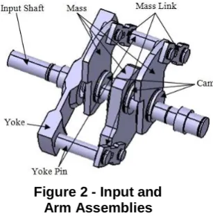
Using the V belt drive between the engine output shaft and the input shaft of the IVT, the IVT will receive input from the engine through the use of that. The input shaft will transmit the torque to a yoke. The yoke has two pins projecting from it as shown in figure 2. The yoke pins are connected to the links.
Figure 2 - Input and Arm Assemblies
The links are in turn pin connected to three masses. These masses are attached to the arm assembly. The core part of the IVT is the method in which the masses interact with the arm assembly. This arm assembly by the rotation of masses allows generating torque. This generated torque transmitted to the output shaft.
The intermediate shaft of the arm assembly has three cams mounted on it. These cams are circular pieces of steel like hollow , David Goldberg, who was able to solve a shaft, which having an offset bore for the arm assembly shaft as shown in the figure 7. Any force acting radically on the cam is translated into a moment which acts on the shaft due to the offset shaft construction. This is
because the center of the cam is offset from the center of the shaft, creating a moment arm.
Figure 3- IVT Cam
The three cams are mounted on arm assembly shaft. These are offset and exactly 180° opposite of the other two cams and each with a bearing press-fit onto it. The center cam is longer in dimension than the other two cams. The length of cam decided according to the dimensions of masses. The weight of central mass is equal to the weight of addition of other two masses. This configuration is made to ensure the balancing of the shaft. The centrifugal forces generate create a moment about the arm assembly shaft as the masses rotates around the cams.
The three cams are mounted on arm assembly shaft. These are offset and exactly 180° opposite of the other two cams and each with a bearing press-fit onto it. The center cam is longer in dimension than the other two cams. The length of cam decided according to the dimensions of masses. The weight of central mass is equal to the weight of addition of other two masses. This configuration is made to ensure the balancing of the shaft. The centrifugal forces generate create a moment about the arm assembly shaft as the masses rotates around the cams. The following four steps explain the oscillatory nature of the torque generated by the IVT.In step 1, the rotating masses generate the centrifugal forces pass through the point of rotation. Therefore it do not generate any moment. At step 2 the centrifugal forces generate a clockwise torque, as the masses have continued to rotate.In step 3 the masses having continued to rotate to the point where their centrifugal forces once again pass through the point of rotation, thus it will cause no moment. In the last step
4 the masses have rotated so that their forces will produce a counter-clockwise torque. For this the maximum torque is calculated by the formula:
T = m.ω2.RCG.DCam Offset (1)
February, 22nd and 23rd, 2019 assembly shaft will be overcome by the moment
developed and the assembly shaft will begin to rotate. From this stage on, the mechanics of the arm assembly and masses will be dynamic. The arm assembly shaft rotating itself and with respect to this one of the four steps above will be occur. The rotationof the masses about the cam will be decreasing as the rotation of the arm assembly shaft increases. With respect to the arm assembly shaft the period of the oscillation will increase. The period of the torque oscillations will approach infinity due to the rotational speed of the arm assembly shaft. At this stage the IVT will act like a direct connection between input and output.
To convert the oscillating torque into unidirectional motion, in IVT uses two sets of one-way clutches. The first set of clutch is between the arm assembly shaft and the support case to the arm assembly. The oscillating torque gets converted into torque pulses in this set of clutches. The clutches operates between the output shaft and the arm assembly shaft is from the second set of the clutches. The purpose of this clutch set is to allow the output shaft to make free to rotate between torque pulses. The vehicle’s wheels would stop and start with every torque pulse without these clutches.
VII. MODELING,DEIGNAND DEVELOPMENT
The Infinitely Variable Transmission (IVT) system is designed to study the various characteristics like torque, power and efficiency across the speed. The components from IVT are designed with the considerations of various factors like material, cost, ease of manufacturing and the reliability of the system. The basic design of the IVT system and its components are done with the 3D modeling software CATIA V5 R20 version. Further made the drawings for the manufacturing to assemble the IVT experimental setup. The design for the Infinitely Variable Transmission system is to be specially designed to get the match with vehicle requirements. Therefore all the design modifications and optimizations are made to achieve top speed, pulling capability and weight/space savings in the IVT. The study is made on the design considerations for all parts and analysis of the critical parts from the IVT system. The basic inputs considered as per the requirement and design calculations done with the
VIII.TESTING
The experimental results related to the torque, power and efficiency of infinitely variable transmission (IVT) are getting in this work. To get the above results we built a special test rig.
Figure 4 - Input and Arm Assemblies
Commutator motor. The effective diameter of dynamometer pulley is 75 mm.The suitable procedure has been followed to obtain the observations and to plot the graphical results. First start motor by turning electronic speed variation knob. Let mechanism run & stabilize at certain speed (say 800 rpm). Then place the pulley cord on dynamometer pulley and add 100 gm weight into the pan. Measure and note down the output speed for this load by using tachometer. For the next reading add another 100 gm weight & take reading. Number of readings taken for various weights as it is increasing by 100 gm in the pan. Tabulate the readings in the observation table and plotted the various characteristics like torque, power and efficiency across the speed. Calculations have to be made for torque, power and efficiency with the readings taken by above procedure. The factors like average speed, output torque, input power,output power and efficiency are calculated for the final results.
Conclusions -
February, 22nd and 23rd, 2019 The current design for the IVT is modeled with the help
of previous parameters determined and validated in the literature. The desktop model is built to demonstrate that the design is constructible and actually functions very well. Comparing the final results with the objectives set for this work, it can be seen that the results and objectives met the requirements. The Infinitely Variable Transmission system run exceptionally smooth while the testing. This modeling of the IVT for an automotive application is demonstrating its high performance characteristics.
References
[1] Mantrioa, “Performances of a series infinitely variable
transmission with type I power flow”. Dipartimento di ingegneria meccanica e gestionale, Politecnico di bari, Viale japigia, 182-70126 Bari, Italy, January 18, 2002.
[2] Giacomo Mantrioa, “Performances of parallel infinitely
variable transmissions with a type II power flow”. Dipartimento di ingegneria meccanica e gestionale, Politecnico di bari, Viale japigia, 182-70126 Bari, Italy, January 18, 2002.
[3] F.Bottiglione, S. De Pinto, G. Mantriota, “Infinitely
variable transmissions in neutral gear: Torque ratio and power re-circulation”. Departimento di meccanica e management, Politecnico di bari, Viale japigia 182, 70126 Bari, Italy, 2014.
[4] Fenwick Jeffrey, Ryan Grimm, Sami Sakalla, Mike Morine, Tom Hopkin, “Design selection for the infinitely variable transmission”, Unpublished, Dalhousie University, Mechanical engineering department, Canada, 2005-2006.
[5] Ion ION, “George Constantinescu’ Torque Converter
Analysis by Simulink”, SISOM 2007 and Homagial Session of the Commission of Acoustics, Bucharest, 29- 31May.
[6] Haycraft, W.C. (1928). Lord Montagu of Beaulieu, “Constantinesco torque converter. Cars and Motor- Cycles”, Vol. III, London & Bath: Pitman. pp. 1171-1178.
[7] Ullrich, K.T. and Eppinger, S.D., “Product design and
development”. 3rd Ed., the McGraw-Hill Companies, Inc., New York, 2004.
[8] Norton, R.L., “Machine Design: An Integrated
Approach”, 2nd Ed., Prentice-Hall Inc., Upper Saddle River, N.J., 2000.
[9] ] Amarsinh Shinde, Subim Khan, “Modeling, Design and
Development of Infinitely Variable transmission System”, International Journal of Scientific Research and Development, Vol. 4, Issue 03, 2016.
[10] Andersen, B.S., “An Investigation of a Positive