PROTOTYPE DEVELOPMENT OF A SINGLE STEP PRESSURE REGULATION SYSTEM FOR THE NATURAL GAS MOTORCYCLE
Dr, Rahmat lbhstn, Dr, ZrJlkefliyaacob, Zulkifli AMul Majjd, Shameed Ashraf ABSTRACT
The use of Compressed Natural Gas (CNG) for vehjcie has proved to improve €misslon quaiity/ reduces dependency of majnstream fuels and increases lubrtcatjon oii lifespan. The successful utilizauon of CNG on the Kriss Nlodenas 11occ has been proven by p.evtous researcher. The current study is carried out in the attempt lo improve the pressure legul€tot whjch isd€emed crucial in dte CNG fuel system, Various d|awback of the previously imptred unt prove the need for dtis strdy. Thjs study begins $/jd] a comprehensive ulrde|standing of dte pressure rcgulation system. Design considerations are taken afd optimized accordingiy to enhance the final prctotype. The flow wiftin the regulator is optjnized using FLUENT+,white the structural integrity is backed by AmericEn Society of MeclEnical Engineer (ASME) pressure vesser ccEe and related standards on threaded fasteners. The fabrication of fie prototype nas Deen fonnulated from findings and anaiysis on the d€sign methodology lsing suitable machining tec.hniques. The p€rformance of the flnal prototype is obtained from the specjally oeveopec p.essure regulato. test bench. It is cleady proved that the developed pressure regulator is capable of providing the downstream components widt natural gas at 48ar up to 24liters per minute. This performance is seen cont@nt fegardless of the upstream piessure ano me dowr$rean flow demand.
. J
1.0 Natural Gas Motorcycle
The flrst generation prototype model of the nafural gas vehjcle motorcycle was designed and developec by the Nacural Gas Vehide-Motorcycle (NGVM) Research Group under Gas Technology Center (GASTEG) of UTM back in 1997. The Kriss l4odenas 110cc was selected as it was the one of dle most wideiy used locally paoduced motorcycle. The four stroke natural gas prototype motorcyde was prepared foa testing with a new set of conversion kjt that includes airltafuidl gas mixer, preasure regulator, storage tanh 'elated conuol elemenEs ano measuring appaidtus rr. The motorcycle was then pqt !o several tests to attain the engine,s p€rToTmance, exhaust ernission and the lubrication oil quality to conduc a comparison between the nafural gas and pefuol operations !'r. The power ouFut of d'e engine and exhaust emission daE wa5 successfully recorded using Ute CycleDyn Pro SF 250 chassis dynamorneEr anc 'lonba vE{A 3241 emissron a']aifzer aL b'e llodenas ass€mbly plant in Gurun, Kedah Phlslc"l aad chemicEt Lesdng or dre
Figure 1: NatuGl Gas Flotorcycle Fuel Ltne 2.O Current Research.
The second generation fuel system under deveiopnrent differs from the previoLsly 'rroiied sys(en In lerms of storage pressure, pressure requlation and fuel metering. The previous system had a sto.age system of 1800 psig as it was conducted on a trial basis. The s€cond generation's designed to'.andle full suppr, pressure of 3000 psig as dispensed at fie CNG re'ueling station. The vacuum actLatea venfuri type Fuei metering device operating wi$ natural gas supply at 5 psig is replaced wlh an .rlection system. The injection system uses an injector actuated by an electronic contlol unit and supplied with natural gas at 4 bar. Difference in storage pressure and the supply pressure of the fuel metering device on dle second generdtion fuel system l_as rmposed a need for the current dudy. The pressure regulato. woulo b€ designed to meet the 3000 psig storage pressure and to supply d'te injectol' with a constant pressure of 4 bar regardless of u1e demand pos€d upon it. This paper would disorss tf|e mechanism, elements, design parameters, add related testing involved in designing a pressure regulator. Among various criteria and consideration that are indicated by market resea.ch I1l, Ute flow periormance, heat exdlange control and oLtlet pressure enor are the prirne goveming factors that are taken into consideration during the design and development of tre regulator,
3.0 Methodology of Res€arch
T'1rs s€cdor covers Lhe med'tods i|rolied rc desrg'l ard developmenr !_e
single tceD pressure regLlator deaicaleo .or tr)e \GVY <nss 110 a.d rre corresponding o.essLre -eguiator fest be^cn, -1e tes! bench enabies performance test to be condrated 01 'he -ewrv devetopeo .eguldtor. 8€sic wo*tng ard -nechariqr of lfe pressJre reguiaton sysler are ioendf,eo and developed pat by part. This wo.k is arranqed n sequel *lich oegi-s wEh lre material selection followed by the design and deveiopment of the rest icting element, loading and measurin! eiement mechani€al hnkage and lastly rne pressLre regutator try, Equal attenUon is given to d1e oressure 'equlator Lest berch, whe-e various comp,onent sele'ction and assembly are conduced !o ensure safe high pressure gawLs fluid flow coupted vvitn suttaole data acquisibon system to monilor thc occuring phenomenon of the regulatio.r system.
3.1 Pressure Regulator Components
Pressurc rcguiators are prmuced ir, many srzes and configurations, oLr all are bounded to three basic coFrponem categories which are the valve Lrody, d.le valve trim and tre actuaror tsl, These components can be further described in lems of elefients which are E-e restricring,
oading and measuring16r. The .oading ano measuring element together form iie acfuating component of the regutaLor. The valve trim comprises the restrictjnq etemenr and relaced link?ges that enables the regulator to operate. The r€stricring element is made up to the \€lve s€at and valve pad or obturator. Lastly ule valve body houses all th;s componenE and orovides physica. Supporl to the components Lo ensure wod€bility.
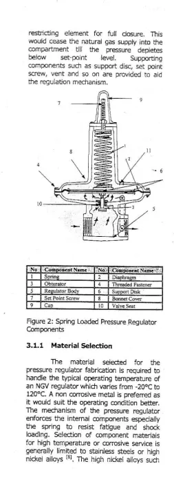
The aegulator is design to provid€ constant outlet pressure regardless of the demand opposed upon it 14. From the flgure be{ow we s€e that d1e loading element (spring) exerts force against the measuring eiemenl (diapl-€gm) wi-icr opens he restrichng el€ment. When rhe cofipartmenr pressuae ej(ceeds tre s€t-porrr level fre measuring element wolld actuate Sle
I
' l
resfictjng elemenE for full ctosufe. This wouid cease the natural gas suppiy into the CorrpArtmeni dl the oressure oepteres
beiow ser oo,n! leve{, Strppor0rE
conDore4l5 sltch as sLpoort d:sc, ser poinr
Screvr, vert aTd so on are provideO rc ajo
file .egL]lation mechanism.
Figure 2: Spring Loaded ftessure .Reg ulator Componmts
3.1,1 Matedal Sel€<tion
The mater'al serected For Lhe pressure regulator fabric"tion is required to handle the typical operating temperature of an \GV regulator whidt varies fronr -206C to 120"C. A non corcsive metal is prefered as it wourd suit the operacing condihon berter. The mechanism oF $e pressure regulaLo-erforces rhe intemar coinponents especiarly U]e sprrng to resisr fatigue End shoc( loading. S€lectjon of conponent lnateria{s for high temperafure or corrcsive service is gene€lly limited to s€rnless stee$ or .tigr nicler arloysL"l. The high ricke{ afoys sucli
as lnconei and $e beryliiumropper are dbouL 3 fo 4 lmes d^e cosr of fype 18_8 stainless s,eet t,l, --here are a rLnoer of groups or far]|lies of inrness sreel, eacn Corrarrt' g a _UmDer of Soeatf( tyoFs arc e9ch wrti ils ow- d stt-gJisl-irg cnaraclersfics. These tnree Lerms_ martensite, ferrite, and auStentte- are aJSo dessroLjve ol .d-e trree
-ajo- .drl:es of stainless sieelsL''r
The martensitic stainless steels are nomi'lajly tl-l3o,o chfoni-n. arc fradenable bv hear rfeaL-lent €'1o arc exerrplrfred bv grade $pes 4rO (S4rOO0) and 420 f5a2000). Thrs q-ade is susceptibility to absorption of atomic nycrogen, resulting in frydrogen-assisted ciacking add has poor low-temperature impact resistance. Fenitic Grades class of al{oys usua ly contains 15-18o/o cnromium The turritic grades, exemplified by S43OOO (16-18c|-0.12C). have corrosion resistance slpenor to the martensitic grades, p.imariiy by virtue of rhetr htqner chromium coT[enL. Their high-temperature oxidation resistance is also gciod bL'r rhey ha,/e ooor impac resisGnce. Heat treatment uFon drcse grades has no effec on its hardness, The austenitic arodp is rhe mo$ imFoftanc.or prcess industry aoplicadons. By urIue of therr aus66;1g 6o-;"9 aloy addirjons. notabiy nickel ard manganese, they are no! hardenable by heEt treatrnen! but can be strain-hardened by cold-wo*. The conventional 18-8 austenitic staintess steels are exenplifed by Type 30a (S3OaOO). These al{oys have rdrc combination of cotrosion resistance, high-temperature strengtf, acd oxidation resistance, ease o. fabdcacion good ouctility and gooo:rpacr resii.ance down to ac leEst -193.c c215.0. Their medEnical prop€rties in general, are excellent.
cannot be heat tr'eated as these alloys do not resoond rc the |-a-denrrg and LemDeflng method sr. At low temperatures the stainless steels of lhe 300 series are usefui, but those of the 4OO series are not lr3l. These arguments above prove that the best common component materiai tlrat would oblige the design requireneni is the
< " F ' n l o c q q o e ' - + 3 0 4 , ap\ - } r s
material would be used throughout the design and fabrication of the pressure fegulator due lo its advantages over other matedais,
3.1,2 Restricting Element
The -e51ricti'1g elemer! desjgn is '- given the prime attention as $is would be the component that would deter..ine the pressure control. The obturator that moves againd and away frcn the v€lve seat to prevent and permit the flow of gas to the regulator compartment serves as the restiicting element. The limiting factor of flow witnin this system is the occufience of choke. The equation governing the area of tl_e conduit ard mass flow s given by oosthuizen and carscallen trqr
u ' = - L [ L 1 " ' u '
' J f ' P " \ / + t JFrom the equation we see that dle mass flow rate drrough the close conduit is proportional to dle closs sectional area of flow. The supply of natural gas froflr ure storage tank is suppiied brough high pressure fubing, the intemal diameter for this commonly us€d tubing for CNG suppiy is 3 mm. The design of a vaive seat with an area larger then this value would be unnecessary as the choke would have aiready occurred downstream where fie diameter is smaller. The desigo of a valve s€at smaller diameter wouid cause further c,hoke and redLrce the mass flow into dle regulator. For this reason, the valve s€at is designed to be 3 |-nrn in diaaneter.
The movement of the obturator which moves against the valve seat to restrict flow and moves as/ay to pernit flow
requires evaluation. How far shouid tfre obtlrator move ln order to provide suiflcient naturai gas to fiaintain d]e desired prcssure within the re€ulator at the feguiators full capacjty? The compliaated gmmetr_y of the flow makes manual cElc!iation tediols, dlus requirinq the use of Computatiofal Fluid Dynarnic Softwa relt5. The impiem€ntEtion oi lhis method helps deiennine the mass flow |ate of gas flowing between d1e valve seat and obturalor at a glven openinq gap. The simul:tion is condlcted on a compressible, steady state condition with adiabatic wall basis. The fluid is taken as methane due to the nature of llalaysian natural gas which contains over 93?o methane.
Various position of the obtltlator from the valve seat is simulated using FLUENTfi Compltational Fluid Dynamic Software. The geometry is generated and meshed using GAMBffft which is a
Computer Aided Design Soft;ware. The : illusbation below depicts the neshed
geometry that would be imported into FLUElffn. The boundary conditions and fluid properties are defined widrin FLUENTft and simulated to obtain fie corresponding mass flow .ate at different oL\turator positions away from the !€lve s€at. The resulls obtained from the simulation a.e comparcd with dle Elermophysical properties provide by NIST 1161. Tne following picture shows the results of fie simulation fiafs shows properties of a plane. This method determines the d€sired opening to provide u]e mass flow rate that would meet fle need of dle natural gas motorc/cle. The sfudy moves on the design
a i s \
g.!;:;i
- il:ii
l : r : :
8 . .
E , r , ,
,
I ii',
result of $e comparbnent fluid acbirg upon rne orapirEgm which seRes as ihe .n€asurlng element. This force resftjcts the entr;nce of the gas to the compartnent wn€n recuces the compartmeft Dressure. B:sed on fundanrental calculations on Forces a|jd knowing lhe desired compafn-nent set polnt presslre and maximum obtu€tor movernent away ftom dte valve seat, suitab{e loading element (spring) oesrqnec.
, , . . , , , , , , , , , . , " , . l l 1 ; l ;ji,,:
' )
t
- t
3,1.3 Mechanical Linkages.
The mechanical linkage relates the restictjng element, measu.ing element and fie lo€ding eiemenc to form a workirg pressure regutation mectranism. The linKage is pivoted to the regulator bocy at Doin! "X,, shown in the diagram. There are t€sically firee forces actjng on the liakage where dle re$ltant of 6ese forces will determine iJr€ actuation of dte resrictirg elernent. The iorce denoreo as "1" is fie force exerteo D, the flujd entering the regulator comDaftment on to the obtuGtor. The rnagnifude of this force varies due to $e depletjng storage pressure. As we know, force is pfesslre acting over a surface area. The force denoted as '2" s caLsed bv tne ore-compression of Ute spring (Loading element). This seEng cause fe compartment pressure to rise, *te greater the force dle greater the comfErbnent pressure. The force denoted as '.3,, is fte
3,1.4 Loading Element
Compression springs made from rounO wtre aae tj-e easiest to oesign End produce. They are accurate. retiable Lolerdole to hrgh stress, have lonqer fatioLe life, and should b€ used in prefere-nce ro in
or.' tr* t'r. *";;- d;ili;:;#
of ends for a Futv formed fel:cal cornpression spring $ey are plain end!, plarn ends grcund, dosed ends aod dosed ends ground. The loading element spring oF tne pressure regutator will be dedgned to have &e closed ends ground as it requires acq.rrate precision force requirements and resistance towards budding.
Th€ single coil of d€ compression spfrng shown in Ule figure below will have d
cnterion for [J-e spr ng wrre will be fle shear s!'engln.
Single Co;ls of Compression Spring
D
Cross Section ofsingle Coil
The twist of 'torqLe" In fle spring wire aL point "C" is d]e load "W" multiplied by the lever arm, tie length of which is D/2, D being the mean diameter of the coil. So, dle torque is 1/2DW. Now, in a round rod subjecr to a hvisdng adjon, the sbess is noc uniform over rhe whole area of fte wire, buL is zero at the core and rnaxiftum at the surface. The maxjmum shear stress is given by
. 1 6 .T ' " z . d '
But T = W. D/2, so that
R . W , f )
f = - . - ( 2 ) or, to put it ff]e other way round,
I . D
Tles€ are dre basrc eqLatior For ioad, where the load which a spring can carry is proportional to the sfess, to tire cube of the wire diameter, and inversely
proportional to d1e coil diarneter. A ten coil sorirg w il carry eraclt Lhe saft e sdfe baa as one with only two if the wire and coil diarneters are Bte same. The number of coils do€s have an effect on the spring terorma'lce: in -any cdses me spri.E deflecdon urder load is a,-rosl as t-rpo(dnL as lhe load ilself, The con-esponding end B oi the bottom haf coil is thus displaced uowards wiere as erd A s d splaced downwards. Tle iota deflect.on s 2 '6 wFere '6" nolecrerl oowrwaros ror poinr A and 6 upwards for B. Add another pair of haF co,ls ano tne rext end wril rrove oy 4 "6". and so on. Deflectjon depends on dre nLn'ber of corls. Ir sprirg wor\ b is deflection is usuaily stated as Sre Rate of d-re soflng 'R" and In Inrpe.ial measure is d€iined as the load i.l lbf/rr. (i- S.I. un,ts 61is would be stated, for our slze of spring, in Ne!^/ton/mm.) rr. Rate shouid be determined between 20 and 60 o/o of total defiFchon when Lesa engrhs are not otherwise established ttal. 'the deflection urder a given load W s g,ve'] oy ftl formLrla below:
- 8 W D ' . n
I
T
W 6
G . d '
8 . D 3 . n (41
From (3) above you will see d]at &e deflection for a given load depends directy on the size of the load, on the cub€ of the coil diameter. on the numb€r of coils, and invelsely as the fourdr power of the wire diameter. And, of cou6e, invelsely as the value of "G", which depends on the material used- and on the temperature of that material, a fact not always remembered when dealing with springs working at fle temperature.
deflectjon is grven as valu€s to equation (1) equatjon (5) and (6).
, , 4 C - l 0 . 6 1 5
4 C -4 C
Kr. Adding drese and (4) we get
Ure outsrde. To recifu thrs condibo., Ere correctton Facor rs Inlloducm. Thc
cDr-ection is also needed becduse rhe wire s
curved wfere t'te curvaEre deFends or me . d t i o o'cotl diare(er lo wi-e oianerer. fh( .or-ec(ion 'aclor fo- snear stress .5 given as (- where as lfe coarecuon -a(tor fof
loterance sor,ngs and tfose suDlected Lo cyclrc lo€orng,'!,
3.1.5 Pressurc Regulator Body
There are bEsicllly two constderations lhat are tnvolved in designing a suttaDLe pressure regulator body. The r.Ie-nEl Conoafrent of the -egutALor boo, rs Cv'rnOnc!' n slape rrtf 50 T-n Oiarnecer and 28 mm ln height. It is fitted with d bonnet cover at the top to ease access to the intemal component. The determinatjon of the mininrum wall thickness of this companment and the bonnet cover is evaluated bas€d on the ASlvlE Boiler and Pressure Vessel @e kion VIn Divisiof 1. The selectioo of suitable threaded fastener to hoid the bonnet cover in p{ace agarnst the internal forces is dealt with in the following section. The matedal used for fe developnenr of the booy is sbinress ste€l 304 as it complies with the pressure vessei code ano sUiG rhe workjng condkion or tlre regurator best. The desiqn woulo carer for fle rull CNG scorage pr;ssure o. 1000 psrg to provide maximum safety as r ;s a preliani.Ery design prototyp€, The bottom wErl, cyliMricat side wall and the bornel covef minimal wail d.tickness are presented ln the final prcduct drawing which is labeiled with dimensions.
3.1.6 Threaded Fasteners
Ore of the d;stinct aovanLaqes of $e l5O mearic nLt strergd sy$en -'s har eacn proFelry class of nut was specificarll designed, dimensionally and rnetallurgicllly, lo orcoerly mate \,ridr a prcperry class of bolt L"r. C-onsequenu, when the conect ciass of nut is selected, even under the mo6t adveEe cohbination of conditions, dte bolt will nomaily break fi|sl This occurrence eases the detection of failures prior to loading. There ar€ just two metric sqe!{ bread forms, dte M profile whidt is dre standard for commercial fastener and fie lvll which is dte standard for aercspace quality fasteners. The Standard commercial fastener 1"1 proflle is selected for fle cltrrent stLdy as it is easily attainable in *re ma*et
2 C 2
D
d
- , - 8 . f i ' . D
' 8 D',.n
and economically favourable. fused on SAE 11199, Solt o'class 4.6 having Y6 r 1 rs seJecied as lt has suitable properq to hold the calculated force e\erted on to the fastener, The gLidet.ne n bott aro -L! seieciror oLtl;r es LhaL d e nLt selecrm shatl be of a higi_er cjass compareo !o tre oo.t. Thereforc based on ASTNl A3561,1 nut f.om class 5, f'16 x1 Hex style 1 was seiected. 3,1.7 Structural Integrity Simulation
The fi-al design of fle des,greo prototype is evaluated in tenn of its sfructural .1'egrity Lsing a sguclural soft\,are based on f,rtte etement ca.leo Nasuan 5/mllar rc me approacn tmP{red in rhe compLrarional flurd dynamic metnoc, the geomeay is set using a computer aided design softt /are cnlled Pafanfr. The figure below shows the model that has be€n neshec, All the cornponenrs previous,, described are housed within this companmenl
3,2 Pressure regulator test Bench Design and Development
The reg-iaror Lesr -,g was cestgnec and buift to gauge the perfonnance of NGV pressure regulators. Suitable ports on the rcgllalof were useo to piace pfessure, 'emoerafL.e ard fow neas.-ng oevices. -ne posiltoring oF the seTsors ar la-oLr co ris of the recu.alor prolioos cornpreiensrve understanding of the -€!Llato-. esDecjallv rl'e abrirY of b-e regllator to leduce presslre and maintain the outlet pressure regardless of the flow den_and dow_rsueam, o-essLre anc te'nperdftre difference after pressure redLction :s o99ed and dr al'ze'o wiLn dris test rig fof varjous oLtlet flow Gtes.
fhrs Lest rg s sutable ro be _sed -o test most NGV pressrrre requlator as d]ey l'ave srr',lar desrqns and ooe.ating pressLre, We couid srmoly remove anc nstarl Ehe probes to accommodate any similar b/pe NGV pressure regulator with the help o. sui(able fittinqs. The dyranic F€rfor_1ance of pressure re!ulator cooing wiu_ fluctuatinE odlet flow ("n be us€d to s€lect regulators
3.2.6 Component S€lection and Assembly
The pressure regulator ten bench comprises of a compilation of equipmenl asserrbled at a desired orientation !o won( as desi€d. It is specially fabricated to provide encouraging working space to conduct test on the .egulator, The bench is cap€ble of holding all the related apparatus in place. The storage c/linder containing high pressure test gas is praced at the top o' ttre b€ndl. This ea*s maintenance slch as charging of gas, leaks checks and enabies qas io d sperse to tre surroundirg ia case o leak
-' j
Frgure 1: Sdlemahc Drawrng of the Pressure Reguiator Test Rig
Pressure sensors selected have measuGble pressure range of 250 Bar down to 0, while thermocouples are picked to suit the typical NGV pressure regulator temp€rature range of -20oC to 120.C Previous test conducted on $e fi|5t generddon fuel System provea a rarmum consumption of 24 Liters per minLte of natural gas at full throtlje. Due to Utis a flow meter having an ooeratjng range oF 0 to 30 Lrrers p€r rrinute was selec-Ld !o worr on fiis lest bendr. Suitable adapters and power sLpply lnils are selecled -esDedvely to c?ter for the equipments. The themocoLlple
s operated wiLh tfe PrCo TC.08 wl_rcl_ :s connected to the personal computer for data oggrrg. Bodr the signals Fom fle pressLre senso€ and the flow meter are process€d by fte Pico ADC'16 powered by trle pel.sonnel computer. Pico iog software p.ov,ded widr bodr the TC-08 ero ADC-16 .s used lo provide rcal time data lc€gin€.
Gas ls transferred from the bulk <torage to tfe s-oGge cyi:nder onooad tl-e lesl bFncf throLgl Ja-iols vatves and frdngs. The _igh pressure so,eno.d ,/aive attached to Lhe regliator is held shut i| the db5erce of elect4c cur-erc usudrly sLppriec when the vehicje is switched on. The po!,ve. supply onboard lhe test bench provides eleclrc cLrrent at suitable volts to Lhe solefioid coii to enable lhe High Pressure Solenoid Vaive to open allowing naturai gas lo erter dle 'i.sr sBge of p.essure aeduction, Pressurd and temperature sensilg are dore before a_d after t"q pressure requlating stage, These ptessure and temperatlre s€nsors will help anallze tl-e conditjons wrthil fle -egLlaror dufl-g operauon. The outlet of the relu{ator js equipped witjr a flow meter and a pressure sensor lo anailze the effects of various flow obtained wid] a help of variable valve. The nacurai gas is Suopried to $e moco.cycte or any vehicle under test.
Nomenclafure: 6 = deflection, inches n = number of active coils
G = Torsional modulus of elasticity Lbf/sq.in.
R= spring rate, lbf/in. of deflection, fs = max. shenr sb-ess, lq/ sq.in. T = Torque, lbr/ in.
W = Load, lbr D = lvlean coii dia. in.
n = 22/7 for dris sort of work. Reference:
1. l,lartin Philip Kng Ik Piau, arlkefli Yaacob, Zulkifli AMui Flajid, Rahmnnt l"lohsin: "Development of Natural Gas l4otorcycle in Malalsia" G€sex 2000, C-onference and Exhibitjon, Pattaya, Thailand, 11-14s s€ptefiber 2OOO. 2. 0r. ZulkefliYaacob, ZulkifliAbdul ltajid,
Flartin Phiiip Kng Ik Piau: "A Study on Exhaust
Ernission, Performance and Lubricating Oil", Jordan Intemational Glem. Eng. Conference III, Amman , )atdan, 27 -29 3. ZLrikifli AMul lvlajid, Zulkefli Yaacob, z
lvlartin Philip King Ik Pia!: "Naturdl cas 17. Cain, T, (1988) "Spring Design &
plotorcycle- Ernission", International f"lanufacture". Workhop practice Series Conference & Exhibition on Natural Gas Number 19. Argus Books
Vehjcle, Yokohama, lapan, 17-20' Limited.
October 2000. 18. Eakin, C.T., (1961) "High rc perdture 4. Heenan, J.5. (1996). "Fuel System Creep of coii Springs,,. pg 77-gt, Spr ng
P.esslre Control Improves NGV Design and
Perforrnance," SAE Technical ApplicEtjon, ivlccfaw-Hill.
Paper 960851. 19. Car.lsof, C.R.H., (1961) "properlies of 5- Whitehouse, R.C. (1993) "The valve and Spring tvtaterials and Allowable Working
aciu€tor user's rnanual", The 8fltish Stresses", Pg 310-313, Spinq Design Valve and ActLrator iqanufacturers and Appllcation, N4ccraw-Hill. Association. llechanical Engtneering 20. "Boiler and Pressure Vessel Code Publicatjons Limited. Sedrion VIiI Division 1" (1977), 6. Floyd D, .1ury. (1972). "Fundamental of American Society of l"lechalrrcal
Gas Pressure Regulation", Technical Engine€rs. ASME.
I4onograph 27, Fisher 21. Blake, A. 1986. "Thrcaded Fast-.nerc". Controls Company. What Ever Engineer Should Know Serjes 7. Floyd D, Jury, (1973). "Flrdamental of Vol. 18. Ivlafcel Dekker, Inc.
l]]ree-l4ode Controllers", Technrcal 22. SAE 11199. 2001. "Mechaniczr anq Monograph 28, Fisher lvlaterial Requircments for f4etric Control Company. 'Externally Threaded Steei Fasteners,'. 8. Stanton, V. A., (1961) "The best Spring 23. A 563 N1.2003. "Standard Specjfication
Material for high Temperature". Pg 31+ For Carbon and Alloy Steel Nuts [fjetric],. 318, Spring Design 24. Standard for Compressed Naiural Gas and Application, llccraw-Hill. (CNG) Vehicular Fuel Systems, NFPA 9. B€ck'4ith, l.B./ (1961) "Flat Spring (National Fire Protection Associatio| )
l4ate.ial Co$ and Stress Facors" Pg 52-1984 122, Spring Design and Application,
IVcGraw Hill.
10. Diilon, C.P./ (1995) "Corrosion Resistance of Stainless Steels", Ivarcel Dekkef, Inc.
11. SAE HS 795 "Flanual on Design and _ Application of Helical and Spiral
Sprjngs". 1990.
12. Warring, R.H. (197:). "Spfing Design and Caicuiation", lvlodel & Allied Pubiications Umited.
13. Carlson, H. (1980). "Springs:
TfoLbleshooung and Failure Analysis . Ivlarcel Dekker, inc.
14. Oosthuizen, P.H., Carstlllen, W. E. (1997) "Compressible Fluid Row" 14cGraw-Hill.
15. Versteeg, H. K., l'4alalasekera, W. (1995) "An Introduction to
Computational Fl-id Dynan;cs, The Finite Vo{ume lvlethod" Prentice Hall. 16, Friend, D.G., Ely, J.F., Irgham, H.
(1989) "Ther.noph)sical Properties of
Mathrna'' I D6\/< ahrm O6F nlE