ABSTRACT
GAMBHIR, MOHIT. Development of a Cycle Level, Full System, x86 Microprocessor Simulator. (Under the direction of Dr. Yan Solihin.)
Although x86 processors are the most popular processors in commercial and scientific
working environment, there is a scarcity of open source microprocessor simulators that
can enable researchers to experiment with new x86 based microprocessor and memory
system designs. Also, most of the simulators that exist today are user space simulators
that do not profile the operating system code that gets executed when interrupts and
system calls are invoked while an application is running. This work involves the
development of a cycle level, full system, x86 microprocessor simulator named MYSim.
One of the biggest challenges involved in developing an x86 based processor simulator is
that the x86 instruction set is complex. Its complexities include variable length
instructions that may take varying number of cycles to decode. Also, the operands in an
x86 instruction may reside in registers or in memory or both. These complexities make
the x86 instruction set architecture (ISA) particularly hard to simulate.
MYSim is an execution driven simulator that is composed of two components: first is the
functional simulator or emulator, which actually executes the simulated application as
well as OS code and second component is the timing simulator, which models the timing
of the application. MYSim uses Bochs (an open source x86 emulator) as the functional
simulator which emulates x86 processors, hardware devices, memory, etc. and enables
the execution of various operating systems and software within the emulation. MYSim’s
The functional simulator executes the next x86 instruction, breaks it into µops and feeds
those µops to the timing simulator. The timing simulator models a full out of order
pipeline with branch prediction, caches, buses and most major components that are
Development of a Cycle Level, Full System x86 Microprocessor Simulator
by Mohit Gambhir
A thesis submitted to the Graduate Faculty of North Carolina State University
in partial fulfillment of the requirements for the Degree of
Master of Science
Computer Science
Raleigh, North Carolina
2008
APPROVED BY
_______________________ _______________________ Dr. Vincent W. Freeh Dr. Eric Rotenberg
___________________________ Dr. Yan Solihin
DEDICATION
BIOGRAPHY
Mohit Gambhir got his B. Tech. in Information Technology from Guru Gobind Singh
Indraprastha University, India in 2005. He worked at Flextronics Software Systems as a
Software Engineer from May 2005 to July 2006 where he was involved in
telecommunication software development. He joined NC State University in fall 2006 to
pursue M.S. in Computer Science. At NC State he worked as a research assistant with Dr.
Edward F. Gehringer during spring 2007. Mohit’s paper: “Animations of Important Concepts
in Parallel Computer Architecture”, which he co-authored with Dr. Edward F. Gehringer and
Dr. Yan Solihin was published in the proceeding of the Workshop on Computer Architecture
Education, held in conjunction with The 34th International Symposium on Computer
Architecture, San Diego, California on June 9, 2007. In fall 2007 he started working in the
ARPERS research group, headed by Dr. Yan Solihin, to extend his independent study work
ACKNOWLEDGEMENTS
I am grateful of the guidance and support of my thesis advisor Dr. Yan Solihin. This thesis
would not have been possible without his precious ideas.
I would like to thank my parents for their unconditional love and for supporting my
education throughout my student life.
I sincerely thank Dr. Eric Rotenberg for developing my knowledge on Microarchiteture and
giving me detailed ideas on how to work with processor simulators. A lot of ideas in this
work have been taken from the simulator that he developed for teaching Advanced
Microarchitecture course at NC State. I would also like to thank him for serving on my
advisory committe.
I would like to thank Dr. Vincent W. Freeh for fostering my knowledge on operating systems
which was helpful in making this full system simulator. I thank him for his constructive
comments and for serving on my advisory committee.
I would like to thank the ARPERS research group for giving me feedback during my
presentation. I would especially like to thank Brian Rogers and Siddhartha Chhabra for
TABLE OF CONTENTS
LIST OF TABLES ... vii
LIST OF FIGURES ... viii
LIST OF ABBREVIATIONS ... ix
INTRODUCTION... 1
1.1 BACKGROUND... 1
1.2 X86 A CISCISA... 2
1.3 MYSIM OVERVIEW AND FEATURES... 3
1.4 CONTRIBUTION... 4
1.5 ORGANIZATION... 4
THE X86 ISA ... 6
2.1 VARIABLE LENGTH INSTRUCTIONS... 6
2.2 FLAG MANAGEMENT AND REGISTER RENAMING... 7
MYSIM ARCHITECTURE... 8
3.1 EXECUTION DRIVEN SIMULATION... 8
3.2 EVENT DRIVEN SIMULATION... 8
3.3 FULL SYSTEM SIMULATION... 9
3.4 ARCHITECTURE... 9
3.5 SERIAL,ON-DEMAND EXECUTION... 11
FUNCTIONAL SIMULATOR ... 12
4.1 BOCHS OVERVIEW... 12
4.1.2 CPU Loop ... 14
4.2 X86 TO µOP CONVERSION... 15
4.3 BOCHS INITIALIZATION... 16
4.4 BOCHS INSTRUMENTATION CALLBACKS... 16
5.1 SESC,MIPSISA BASED MICROARCHITECTURE SIMULATOR... 18
5.1.1 Static and Dynamic Instructions... 19
5.2.1 Fetch Engine in MYSim ... 20
5.3 MISPREDICTED PATH... 21
SIMULATION RESULTS ... 23
6.1 VARYING CACHE SIZE... 24
6.2 VARYING PROCESSOR PARAMETERS... 25
6.3 SIMULATION SPEED...27
CONCLUSION AND FUTURE WORK ... 28
7.1 CONCLUSION... 28
7.2 FUTURE WORK... 29
7.2.1 Adding an Instruction Buffer ... 29
7.2.2 CMP/SMP support ... 30
REFERENCES... 31
APPENDICES ... 32
APPENDIX A:BOCHS CONFIGURATION AND INSTRUMENTATION... 33
A.1 Configuration File... 33
A.2 Bochs Instrumentation Callbacks ... 35
APPENDIX B:MICRO-OPERATION INSTRUCTION CLASS... 37
B.1 Data Members... 37
B.2 Member functions ... 38
APPENDIX C:KEY DEFINITIONS... 39
C.1 Pipelining ... 39
C.2 Superscalar Processor ... 40
C.3 Out of Order Execution... 40
C.4 Branch Prediction... 42
C.5 Architecture Registers... 42
LIST OF TABLES
TABLE 6-1:BASE CONFIGURATION PARAMETERS... 23
TABLE C-1:PROCESSOR PIPELINING... 39
TABLE C-2:SUPERSCALAR PROCESSORS... 40
TABLE C-3:IN ORDER EXECUTION... 41
LIST OF FIGURES
FIGURE 3.1TIMING AND FUNCTIONAL COMPONENTS... 10
FIGURE 4.1BOCHS CODE FOR A SINGLE X86 INSTRUCTION... 13
FIGURE 4.2BOCHS CPU LOOP FOR EXECUTING INSTRUCTIONS... 14
FIGURE 4.3 X86 TO µOPS CONVERSION... 15
FIGURE 5.1SESC INTERFACED WITH MINT ... 18
FIGURE 5.2SESC INTERFACED WITH BOCHS USING RPT ... 20
FIGURE 6.1NORMALIZED L1 CACHE MISSES PER INSTRUCTION... 24
FIGURE 6.2ABSOLUTE L1 CACHE MISSES PER INSTRUCTION... 25
FIGURE 6.3NORMALIZED IPC WITH DIFFERENT PROCESSOR CONFIGURATIONS... 26
FIGURE 6.4SIMULATION SPEED... 27
FIGURE 7.1OPTIMIZATION USING AN INSTRUCTION BUFFER... 29
LIST OF ABBREVIATIONS
CISC Complex Instruction Ser Computer
ISA Instruction Set Architecture
RISC Reduced Instruction Set Computer
SMP Symmetric Multiprocessor
SESC SuperESCalar Simulator
RPT RePlay Tansmogrifier
CMP Chip Multiprocessor
ATA Advanced Technology Attachment
IF Instruction Fetch
ID Instruction Decode
EX Execute
MEM Memory
WB Write Back
RE Retire
PC Program Counter
SMT Simultaneous Multithreading
C
C
h
h
a
a
p
p
t
t
e
e
r
r
1
1
I
NTRODUCTION1.1
Background
X86 microprocessors are ubiquitous. They are used everywhere in the software industry,
research labs as well as in personal computers at homes and offices. Since it is expensive to
design and fabricate microprocessors, researchers typically use microprocessor simulators to
propose new designs and features that will improve the current state of the art. There are
very few open source x86 based simulators available that can be used by computer
architecture researchers to experiment with new x86 based microprocessors and memory
system designs. Also, most of the simulators that exist today are user space simulators which
in contrast to full system simulators do not profile the operating system code that gets
executed when interrupts and system calls are invoked while an application is running. Refer
to [1] for a comprehensive list of available simulators. There are eight full system simulators
available out of which only two x86 based.
Simics [2] and PTLsim [3] are two well known x86 based full system simulators of which
Simics is not open source. PTLsim, is an open source simulator that models x86 processor
with configurable levels of details. PTLsim provides two modes of execution. It can be used
Linux applications. In the full system mode, it integrates with the Xen[4] hypervisor.
PTLsim requires the host platform to be a 64 bit machine and only runs Xen compatible
operating systems. The stringent requirements that PTLsim puts on the host platform and on
the simulated applications has restricted its popularity in the research community.
In this work we developed a cycle level, full system, x86 microprocessor simulator called
MYSim that will be made open source and that can be readily used by researchers on their
existing systems without requiring 64-bit machines.
1.2
X86 a CISC ISA
One of the challenges in developing an x86 based simulator is that the x86 instruction set is a
CISC (Complex Instruction Set Computers) like ISA (Instruction Set Architecture). Its
complexities include variable length instructions that take varying number of decode cycles.
Also, the operands may reside in registers, memory or both. Some other instances where the
complexity of the x86 instruction set is highlighted include a total of 482 instructions; ADD
instruction has 14 variants; there are instructions such as PUSHAD for pushing all general
purpose registers on the stack, etc.
X86 microprocessors break these complex instructions into simpler RISC (Reduced
Instruction Set Computer) type instructions called µops (micro-operations). These µops then
independently flow through the out of order pipeline until they are ready to be retired. µops
that constitute a single macro instruction are retired together.
1.3
MYSim Overview and Features
MYSim is a cycle level, full system x86 microprocessor simulator that models a superscalar,
out of order pipeline. It also simulates branch prediction, caches, buses, and most major
components that are required to model the timing of a modern day microprocessor.
MYSim provides a great flexibility in changing the configuration of the system. For example,
a level 3 cache can be added to the system just by making changes to the configuration file
and does not require re-compiling the simulator. Similarly, different kinds of branch
predictors, oracle, 2-bit, 2-level, hybrid, static, etc. can be used. We can change processor
parameters like decode width, issue width, retire width, reorder buffer size, number of
physical registers, issue queue size simply by changing the configuration file. All the above
highlighted features of MYSim are inherited from SESC [5] (SuperESCalar Simulator).
MYSim is an execution driven simulator which, on a high level, can be viewed as consisting
of two distinct components. The first component is the functional simulator which is built
using Bochs [6] (an open source x86 emulator). Bochs emulates x86 processors, hardware
devices, memory, etc. and enables the execution of various operating systems and software
within the emulation. The functional simulator executes the simulated application along with
the OS code that gets invoked while the application is running. The second component is the
timing simulator that models the timing and performance of the configured system. The
functional simulator returns instruction objects to the timing simulator. The instruction
objects contain all the necessary information required to accurately model the timing. This
includes the opcode of the instruction, source and destination architecture registers along
the timing simulator to calculate the time that the instruction will take to flow through the
pipeline.
Another important aspect of the functional simulator while working with x86 ISA is to
convert the x86 instructions into µops. MYSim uses RPT [7] (Replay Transmogrifier) for
this purpose. RPT is a general purpose instruction decoder that breaks the CISC instructions
into µops.
1.4
Contribution
The main contribution of this work is to bring all these different components (Bochs, RPT
and SESC) together and integrate them into a full system simulator. The work was made
more challenging by the fact that there was not much documentation available for the tools
that were used in this work. Most of the work was done by going through the source code
files and understanding the functionality and various interfaces that could be used. The main
focus however was the porting of SESC for x86 ISA.
1.5
Organization
The remainder of this document is organized as follows: Chapter 2 discusses the x86 ISA in
greater details and analyzes its complexities that make it hard to simulate in software.
Chapter 3 gives the high level overview of MYSim, discussing its various components and
how they are integrated to work in a co-operative manner to produce the results of the
simulation. Chapter 4 describes the functional component of the simulator which is built
using Bochs and RPT. Chapter 5 describes the timing model which is ported from
benchmarks on MYSim. Lastly, chapter 7 concludes the report and gives directions for future
C
C
h
h
a
a
p
p
t
t
e
e
r
r
2
2
T
HE X86
ISA
As mentioned earlier in Chapter 1, x86 is a CISC ISA which makes it harder to simulate in
software. This chapter discusses some of the complexities that need to be addressed while
developing an x86 based processor simulator.
2.1
Variable Length Instructions
X86 instructions are variable length instructions constituting the opcode, register and /or
memory operands, immediate data and address displacements. This makes x86 instructions
hard to decode, both in the real as well as simulated processor. As is done in most x86
processors they need to be broken down into smaller RISC like instructions called µops,
before they can be used to simulate the timing. Even after converting into µops, not all
instructions will be symmetrical in terms of their source and destination registers since some
of the instructions will have immediate data as one of the operands. Also, many instructions
read and write to the flag register in addition to the source and destination registers. This
information is implicit in the opcode of the instruction and should be addressed while
identifying the dependences among the instructions. More on register renaming and flag
2.2
Flag Management and Register Renaming
Many x86 instructions modify some or all of the processor’s numerous status and condition
flag bits, five of which are relevant to normal execution: Zero, Parity, Sign, Overflow and
Carry. This leads to false dependencies between instructions that read and/or write to
different bits of the flag register.
A solution to this problem as implemented in the PTLSim simulator is as follows: In
accordance with the ZAPS (Zero, Auxiliary, Parity and Sign) rule, that any instruction that
modifies Zero, Parity and Sign flags updates all three flags together, so only three flag
entities need to be tracked while identifying the dependencies among the instructions,
overflow flag, carry flag and ZPS flags (a combination of zero, parity and sign flag).
The 5 flag bits can be attached to each physical register and all the instructions can consume
or write to these bits when they are executed. It should be noted, however, that not all the
instructions consume or produce the flag bits. To keep track of the dependencies between the
producer and consumer of these flag bits, 3 rename table entries are maintained. Each entry
points to the latest instruction that wrote the corresponding flag. In case that instruction has
retired then the corresponding entry is NULL and the consumer can be scheduled for
C
C
h
h
a
a
p
p
t
t
e
e
r
r
3
3
MYS
IMA
RCHITECTURE3.1
Execution Driven Simulation
MYSim is an execution driven simulator, which in contrast to a trace driven simulator
actually executes the instructions from the application binary within the simulation
environment. A trace-driven simulator on the other hand works with a prerecorded stream of
instructions that are generated with a specific input. Execution driven simulators need an
emulator module (also referred to as the functional simulator) that reads the application
binary and executes the instructions on the host machine either directly, as is done in
PTLSim using virtualization software – Xen, or by decoding each instruction and executing it
on the simulated processor hardware. More about the second technique is discussed in the
next chapter.
3.2
Event Driven Simulation
There are two dominant techniques of simulating a system in software. These are:
Event driven simulation.
In the exhaustive scheme of simulation, the state of the system is tested every clock cycle,
regardless of whether there is a change in the state during that cycle or not. This leads to a
tremendous waste in computing resources. Exhaustive simulation is sometimes also called,
cycle driven simulation. In contrast to exhaustive simulation, event driven simulation only
examines the cycles in which the state of the system is changed and thus saves a lot of
computing power.
MYSim is essentially an event driven simulator. Though many functions in the processor
core are called every cycle, major chunk of the processing is done using functions that are
called only as needed using events.
3.3
Full System Simulation
MYSim is a full system simulator which models the core x86 processor, peripheral devices,
memory, buses, interconnection networks and allows real operating system and device
drivers to be run, and not just a single program. Full system simulators are becoming
increasingly useful in the multicore computing environment to study the impact on
performance of simultaneously running programs over different cores while they share
various system resources like cache and memory bandwidth
3.4
Architecture
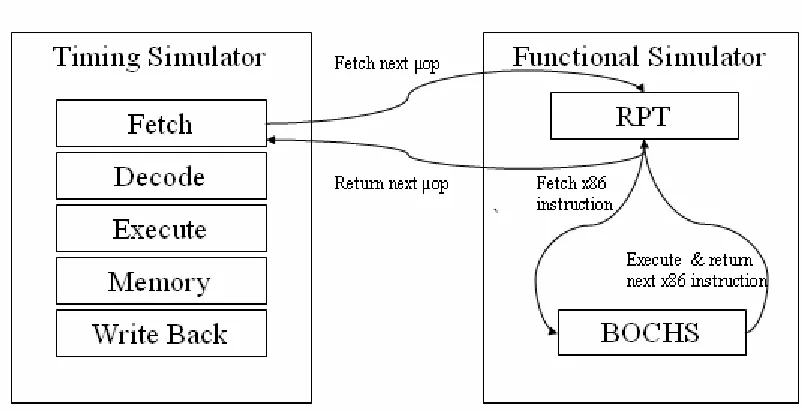
The high level view of MYSim consists of two distinct components: the functional simulator
or the emulator which is built using Bochs and the timing simulator which is ported from
SESC. The following figure shows these two components and illustrates how they are
Figure 3.1 Timing and functional components
The timing simulator models processor pipeline and memory hierarchy. The fetch engine of
the timing simulator integrates with the functional simulator. In every clock cycle, the fetch
function invokes the functional simulator to get the next instruction. The functional simulator
is itself composed of two components. The front end of the functional simulator is made of a
tool called RPT (Replay Transmogrifier), which was built at the University of Illinois at
Urbana Champaign. RPT serves as a wrapper around Bochs and breaks the x86 instructions
that Bochs provides into µops. It then returns the µops in the form of instruction objects that
contain all the information required to model the timing. More details about the functional
simulator are given in the next chapter.
The µops then flow through the pipeline in the timing model using up the modeled resources
processor cycles. In case the resources are not available or the data is not
ready, then events are generated to occur in the future clock cycles depending on the time
those resources or data will be available. As an example, instructions are fetched every cycle
from the functional simulator and stored inside a queue data structure. Instructions from this
queue are checked every cycle whether they can be issued to the execution units or not. If
they cannot be issued due to unavailability of resources then they stay in the queue and
checked again in the next cycle. However if they can be issued then an event is generated for
the time the instruction will complete execution depending on the latency of the operation.
3.5
Serial, On-demand Execution
Although the two components of the simulator are completely independent of each other and
only share the instruction objects, they work in a serialized fashion. The functional simulator
executes the next instruction on-demand, when it is needed by the timing simulator. A
solution to this problem is discussed in Chapter 7 and is left at future work to improve the
C
C
h
h
a
a
p
p
t
t
e
e
r
r
4
4
F
UNCTIONALS
IMULATORAs mentioned in the previous chapter functional simulator is the execution engine that
emulates a real processor and actually executes the instructions to provide the timing
simulator all the information that it requires to model accurate timing. This information
includes memory addresses, control flow of the programs based on the input values, input
and output registers along with their values etc.
MYSim uses RPT (Replay Transmogrifier) which is a general purpose instruction decoder
that is interfaced with Bochs (an open source x86 emulator) to convert the x86 instructions
into µops. The following two subsections give an overview of the two components that the
functional simulator is composed of.
4.1
Bochs overview
Bochs is an open source x86 emulator that interprets all instructions from power up to reboot.
It includes emulation of the x86 CPU, hardware devices, memory and other common
input/output devices. Bochs can be compiled to emulate 386, 486, Pentium, PentiumII,
PentiumIII, Pentium4 or x86-64 CPU. It can also be compiled for use as an SMP or a CMP
Bochs allows the user to run advanced operating systems such as Linux, Windows (XP and
Vista), etc within the emulation environment just like a virtual machine. However, there is a
significant difference in the implementation details, performance and use of virtualization
software like Xen and an emulator like Bochs.
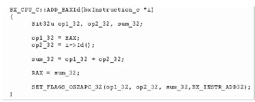
Bochs achieves processor emulation by software simulation of every x86 instruction. For
example, consider the following x86 assembly instruction:
ADD EAX, immediate_data
The above instruction adds an immediate value (stored in the instruction itself) to EAX
register and stores the result back in EAX. Bochs maintains variables corresponding to all the
architecture registers of the processors. It first decodes the instruction that it reads in the
machine code format from the executable. Then it converts the machine code into the
following C++ code:
Similar functions are written for all the x86 instructions with all the different combinations of
operand types. This makes Bochs significantly differ from a virtual machine which executes
the instruction on the native machine as such, without modifications (as much as possible). It
traps and emulates only those instructions that require a higher privilege level. The advantage
of software emulation is that it makes Bochs independent of the native instructions of the
underlying machine. But on the other hand, it also makes Bochs a lot slower than virtual
machines.
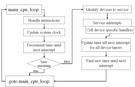
4.1.2 CPU Loop
The above figure gives a general idea of the CPU loop that executes infinitely to simulate
x86 instructions inside Bochs. First it fetches and executes a fixed number of instructions.
It then updates the system clock and also decrement the time until next interrupt. The
interrupt timer is maintained as a counter named num_cpu_ticks_remaining. When
this counter reaches zero, the timers corresponding to each of the interrupts are checked to
see that which one(s) expired. The interrupts that need to be serviced are handed next. The
remaining time is updated in the timers corresponding to the other interrupts. In the final
step, num_cpu_ticks_remaining is updated as the minimum of remaining times for
each timer.
4.2
X86 to µop Conversion
MYSim uses RPT which is a general purpose instruction decoder that transforms specific
ISA into general purpose µops. It is interfaced with Bochs to produce x86 µops.
RPT acts as glue between the timing simulator and Bochs. Timing simulator can only work
with RISC type instructions and Bochs executes x86 instructions directly. So RPT bridges
this gap by taking the Bochs instruction object and breaking it down to multiple µop
instruction objects.
The above figure shows the conversion of POP instruction that pops an element from the
stack, into two µops. The first µop is a load that gets the data from the stack into EAX
register and second µop decrements the stack pointer ESP to point to an older entry in the
stack.
RPT populates arch_uop_c class objects with the decoded information of each of these
µops that is needed by the timing simulator. Appendix B lists some of the member functions
and data members of arch_uop_c class that are used by the timing simulator.
4.3
Bochs Initialization
Since MYSim is a full system simulator, so it needs to skip the instructions that get executed
during booting and initialization of the operating system. Currently RPT, skips configurable
number of instructions that can be specified in the Bochs configuration file. During this
phase, both RPT and timing simulator are turned off and only Bochs executes the
instructions.
This scheme has a drawback that the number of instructions needs to be changed when the
kernel that’s loaded over the Bochs disk image is changed. A solution to this problem may be
to use a magic instruction at the start of each benchmark to signal the simulator that the
operating system had booted and has started to run the application binary.
4.4
Bochs Instrumentation Callbacks
Bochs exposes an instrumentation library that can enable its use as front-end of a timing
simulator. Appendix B contains a list of all the instrumentation callback functions. The API
commits already executing instruction and starts executing a new one,
bx_inst_lin_read and bx_instr_in_write are called when Bochs simulator
executes a memory access, bx_instr_cnear_taken is called when the currently
executed instruction is a conditional branch and is taken.
Though the current version of MYSim does not use this instrumentation library, it was used
in the early stages of this work before RPT was found. The current implementation of
MYSim is such that the timing simulator is in the front end and it drives the functional
simulator (Bochs) forward whenever it needs more instructions.
The earlier version of MYSim used some of the instrumentation callback functions to add a
memory model to Bochs that did not give any cycle level information but generated statistics
related to the memory hierarchy such as, number of read and write misses at various levels of
the cache, total number of memory accesses, memory traffic, coherence statistics in a
C
C
h
h
a
a
p
p
t
t
e
e
r
r
5
5
T
IMINGS
IMULATOR5.1
SESC, MIPS ISA based Microarchitecture Simulator
MYSim uses the timing model of SESC which is a MIPS ISA based microarchitecture
simulator. SESC originally uses MINT (MIPS Interpreter) as its functional simulator. As part
of this work, SESC was ported to x86 ISA for which MINT was replaced by Bochs. The
following figure shows how SESC initially interfaced with MINT.
GProcessor class coordinates interaction between various stages of the pipeline. The fetch
stage which is modeled by the FetchEngine class invokes the emulator. Emulation is
controlled by the ExecutionFlow class. The upper level interface for the ExecutionFlow
class is the executePC() function. ExecutePC() calls exeInst() which after
performing certain validation checks executes the next instruction by simulating the ISA in
software, similar to the way it is done in Bochs which was described in the previous chapter.
ExecutePC() returns an object of the DInst class which represents dynamic instruction.
Next section gives details about DInst class and also talks about an interesting
optimization in SESC that was lost while porting it to support full system simulation.
5.1.1 Static and Dynamic Instructions
Instruction class represents static instructions in SESC. Static instructions are created
during initialization phase. A function reads the application binary, decodes all the
instructions and populates a table of Instruction class objects. Instruction class
stores instructions in an internal format that makes execution faster. It contains the source
and destination architecture registers, instruction type or functional unit that the instruction
will be using (branch, load, store, integer arithmetic and floating point arithmetic), a pointer
to a function to execute the specific instruction (such as floating point addition), a pointer to
the next instruction, a pointer to branch target if one exists.
Dynamic instructions represented by DInst class are specific instances of static instructions.
Dynamic instructions are created by the execution logic by providing specific values to data
dependency information, stage of the pipeline the instruction is currently present in; CPU the
instruction belongs to (relevant in case of an SMP system) etc.
The concept of static and dynamic instances of instructions makes emulation faster because
instructions don’t need to be read from the binary and decoded before execution. This
optimization was lost when SESC was detached from MINT and integrated with Bochs. This
is attributed to the fact that Bochs is a full system emulator so along with the instructions
from the application binary, operating system code also gets executed which is hard to
decode in the initialization phase.
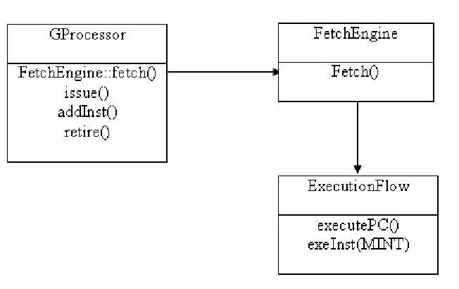
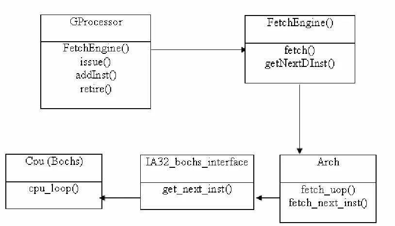
5.2.1 Fetch Engine in MYSim
Figure 5.2 shows the classes and their member functions that integrate the functional and
timing simulator in MYSim.
ExecutionFlow class that provided the emulation interface was removed in MYSim.
Fetch() function in MYSim calls fetch_uop() that provides an interface to RPT to
fetch the next micro-op. Fetch_uop() function invokes fetch_next_inst() function of
IA32_bochs_interface class that interfaces RPT with Bochs. Bochs executes the
cpu_loop exactly once, to generate an x86 instruction which is then broken down into
micro-ops by RPT inside fetch_next_inst().
GetNextDInst() function was added to the FetchEngine class to populate the field of
DInst class object from arch_uop_c object returned by fetch_uop() function.
Arch_uop_c class is now analogous to the Instruction class in SESC, the difference
being that its objects are created dynamically whenever a new micro-op is fetched while
Instruction class objects were created once during the initialization phase.
Most of the modifications made to SESC are in the fetch engine. DInst object is populated
using the arch_uop_c in the fetch engine and is used at most places in the simulator. So
the code working with DInst object did not need to be changed.
5.3
Mispredicted
Path
An important feature that existed in SESC and was lost while porting it to MYSim was that
of modeling mispredicted path. Once a branch is mispredicted then in a real processor the
instructions from the wrongly predicted path will enter into the pipeline and will be there
were already present in the static instruction table that was filled at the
time of initialization. When a branch was predicted then the wrong path instructions were
inserted in the pipeline carrying a fake bit with them to identify that they belonged to a
mispredicted path. However, this feature is lost because there is no static table of instructions
in MYSim. The instructions that it receives from the functional simulator are the ones that
actually get executed inside Bochs. So in order to approximate the effect of executing
C
C
h
h
a
a
p
p
t
t
e
e
r
r
6
6
S
IMULATIONR
ESULTSThis chapter shows some of the processor and memory system statistics generated by
MYSim for SPEC 2000 benchmarks.
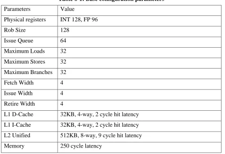
Following table shows the configuration of the base system. All the parameters listed here
are configurable in MYSim.
Table 6-1: Base configuration parameters
Parameters Value
Physical registers INT 128, FP 96
Rob Size 128
Issue Queue 64
Maximum Loads 32
Maximum Stores 32
Maximum Branches 32
Fetch Width 4
Issue Width 4
Retire Width 4
L1 D-Cache 32KB, 4-way, 2 cycle hit latency
L1 I-Cache 32KB, 4-way, 2 cycle hit latency
L2 Unified 512KB, 8-way, 9 cycle hit latency
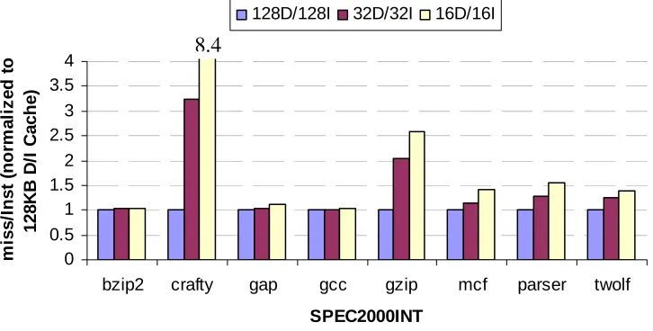
6.1 Varying Cache Size
In this section we vary L1 cache size and observe the change in number of misses per
instruction. As the cache size is decreased the number of misses per instruction is expected to
increase. All other parameters are kept constant. The following graph shows the number of
misses for three different L1 cache sizes: 128KB D-Cache/I-Cache, 32KB D-Cache/I-Cache
and 16KB D-Cache/Cache. The graph is normalized to the case when both D-Cache and
I-Cache are 128KB.
Normalized L1 cache misses/Inst
0 0.5 1 1.5 2 2.5 3 3.5 4
bzip2 crafty gap gcc gzip mcf parser twolf
SPEC2000INT mis s /In s t ( n o rma liz e d t o 12 8K B D /I C ac h e)
128D/128I 32D/32I 16D/16I
8.4
As can be seen from the graph, there is a general trend that the number of misses per
instruction increases as the cache size is decreased. Memory intensive benchmarks like mcf
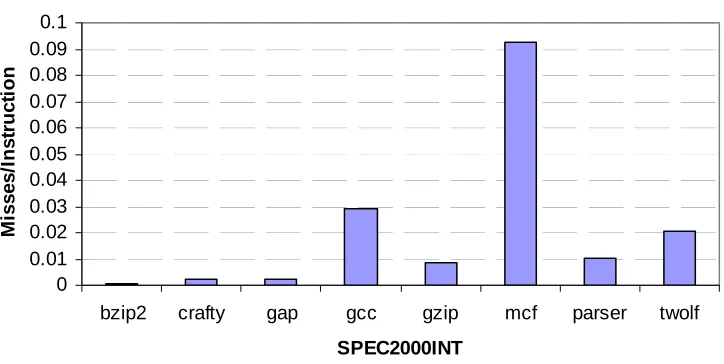
have a higher absolute number of misses and thus show a lower relative increase. The graph
in the next figure confirms this fact. The next graph shows the absolute misses per instruction
for different benchmarks. The cache size for this plot is taken as 32KB.
Absolute cache misses/instr.
0 0.01 0.02 0.03 0.04 0.05 0.06 0.07 0.08 0.09 0.1
bzip2 crafty gap gcc gzip mcf parser twolf
SPEC2000INT M is s e s /In s tr u c tio n
Figure 6.2 Absolute L1 cache misses per instruction
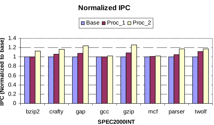
6.2
Varying Processor Parameters
For this experiment, cache sizes were kept constant and ROB size, issue queue length and
number of physical registers are varied. The following three configurations were used for this
Base: ROB – 128, Issue Queue – 64, Physical Registers - 128 (INT)
Proc_1: ROB – 192, Issue Queue – 96, Physical Registers - 192 (INT)
Proc_2: ROB – 256, Issue Queue – 128, Physical Registers - 256(INT)
Normalized IPC 0 0.2 0.4 0.6 0.8 1 1.2 1.4
bzip2 crafty gap gcc gzip mcf parser twolf
SPEC2000INT IPC ( N o rma liz e d t o b a s e )
Base Proc_1 Proc_2
Figure 6.3 Normalized IPC with different processor configurations
It can be seen from the graph that the IPC increases when the instruction window is
increased. This is because the processor is able to find more number of independent
instructions by looking farther ahead into the instruction stream. The gain in IPC is not
significant as was expected because of the bottleneck created by parameters like, maximum
number of branches, maximum number or loads and stores. These parameters were not
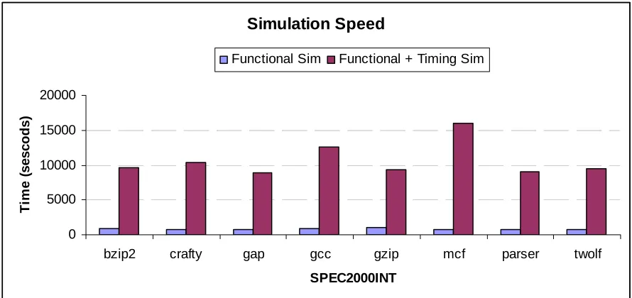
6.3
Simulation Speed
The following graph shows the simulation speed in seconds when the full simulator is
running as compared to the time taken by the functional simulator only. It can be seen that
the simulator spends most of the time modeling the timing of the applications rather than
executing the instructions inside the functional simulator.
Simulation Speed
0 5000 10000 15000 20000
bzip2 crafty gap gcc gzip mcf parser twolf
SPEC2000INT
T
im
e (
sesc
o
d
s)
Functional Sim Functional + Timing Sim
C
C
h
h
a
a
p
p
t
t
e
e
r
r
7
7
C
ONCLUSION ANDF
UTUREW
ORK7.1
Conclusion
In this work MYSim: a full system, x86 microprocessor simulator was developed which will
be made open source and will help the computer architecture researchers in experimenting
with new x86 based microprocessors and memory system designs. It was developed by
integrating SESC (MIPS based microarchitecture simulator), Bochs (an x86 emulator) and
RPT (a general purpose instruction decoder). The main contribution of this work is the
porting of SESC to support x86 ISA. This was done by removing the MIPS emulator from
SESC and integrating it with Bochs using RPT. The work also involved removing all MIPS
specific code from SESC and replacing it with x86 specific code.
SESC users can easily migrate to MYSim. Most of the changes that will have to be made in
order to experiment with new processor and memory system designs are expected in the
timing simulator which is derived form SESC. So the researchers who are familiar with
SESC will not have to learn working with an entirely new simulator in order to move to x86
ISA. MYSim will also eliminate the need of cross compilers which are often required to
compile the benchmarks when the host machines are x86 based and the simulator supports a
7.2
Future Work
7.2.1 Adding an Instruction Buffer
As mentioned in section 3.5, the functional and the timing simulator currently work in a
serialized manner. The functional simulator executes and returns a micro-op only when the
timing simulator fetches one from it. This serialization chain can be broken by adding an
instruction buffer between functional and timing simulator as shown in the figure below.
Figure 7.1 Optimization using an Instruction Buffer
By adding this instruction buffer, functional simulator can independently run on a separate
consume these µops from the start of the instruction buffer if they are ready. It will become a
typical producer-consumer problem with instruction buffer being the shared resource.
7.2.2 CMP/SMP support
Currently MYSim only works for a single processor. Multiprocessor support needs to be
added to the simulator. Both timing simulator and Bochs already have multiprocessor
support. RPT, however needs to be modified to fetch µops from different processors that are
simulated inside Bochs. Currently it fetches µops only from BX_CPU[0] (i.e. the first
element in the processor array inside Bochs).
R
EFERENCES[1] WWW Computer Architecture Page: Simulators. http://www.cs.wisc.edu/~arch/www/tools.html
[2] P. Magnusson et al. Simics: A Full System Simulation Platform. IEEE Computer, Feb. 2002 (Vol 35 N 2), p50.
[3] M. Yourst. PTLsim User’s Guide and Reference. Technical report at http://www.ptlsim.org
[4] Xen Community Overview. http://www.xensource.com/xen
[5] P. Ortego, P. Sack. SESC: SuperESCalar Simulator. Tech Report, Dec. 2004. http://sesc.sourceforge.net/sescdoc.pdf
[6] Bochs IA-32 Emulator Project. http://bochs.sourceforge.net
[7] Sanjay Patel. Replay Transmogrifier, ACS Simulation Tools, Advanced Computing Research Group, University of Illinois at Urbana Champaign
http://www.crhc.uiuc.edu/ACS/tools/rpt/about_rpt.html
[8] T. Austin et al. SimpleScalar: An Infrastructure for Computer System Modeling. IEEE Computer, February 2002
[9] The M5. Simulator System. http://m5.eecs.umich.edu
[10] J. Veenstra, R. Fowler. MINT: a front end for efficient simulation of shared-memory multiprocessors. Proc. of Modeling, Analysis, and Simulation of Comp and Telecom Systems, 1994, p201.
A
A
p
p
p
p
e
e
n
n
d
d
i
i
x
x
A
A
B
OCHS CONFIGURATION AND INSTRUMENTATIONA.1 Configuration File
The following figure shows a sample configuration file for Bochs that gives an overview of
Figure A.1 Bochs configuration file .bochsrc
Given below is the description of some of the parameters:
CPU: Defines the CPU related parameters. In the above example Bochs is compiled
for SMP support and it is configured to have two processors with two cores and each
core supporting two threads. We can also specify quantum as maximum number of
instructions that each processor is allowed to run before giving control to another
processor. IPS is the number of simulated instructions that Bochs is capable of
running per second on the host machine. This is significantly lower than the host
machine capacity because each simulated instruction produces many instructions to
be executed on the host platform.
Megs: Amount of physical memory in megabytes.
Ata[0-3]: ATA controller for hard disks and CD ROMS. Up to four ATA channels
can be enabled. For each channel the two base I/O addresses and the IRQ number
Ata[0-3]-Master, Ata[0-3]-Slave: Used to specify the type and characteristics of all
attached ATA devices. They can be made to point to a hard disk image, CDROM,
ISO file or physical CDROM device.
Boot: Defines the boot sequence. Multiple boot devices can be specified and the order
in which they are listed becomes the boot sequence.
A.2 Bochs Instrumentation Callbacks
void bx_instr_init(unsigned cpu); void bx_instr_shutdown(unsigned cpu); void bx_instr_reset(unsigned cpu); void bx_instr_hlt(unsigned cpu);
void bx_instr_new_instruction(unsigned cpu);
void bx_instr_debug_promt(); void bx_instr_start();
void bx_instr_stop(); void bx_instr_print();
void bx_instr_cnear_branch_taken(unsigned cpu, bx_address new_eip); void bx_instr_cnear_branch_not_taken(unsigned cpu);
void bx_instr_prefix(unsigned cpu, Bit8u prefix);
void bx_instr_interrupt(unsigned cpu, unsigned vector); void bx_instr_exception(unsigned cpu, unsigned vector);
void bx_instr_before_execution(unsigned cpu, const bxInstruction_c *i); void bx_instr_after_execution(unsigned cpu, const bxInstruction_c *i); void bx_instr_repeat_iteration(unsigned cpu, const bxInstruction_c *i);
void bx_instr_mem_code(unsigned cpu, bx_address linear, unsigned size); void bx_instr_mem_data(unsigned cpu, bx_address linear, unsigned size,
unsigned rw);
void bx_instr_lin_read(unsigned cpu, bx_address lin, bx_address phy, unsigned len);
void bx_instr_lin_write(unsigned cpu, bx_address lin, bx_address phy, unsigned len);
There are a total of thirty seven such functions that are called from within the Bochs code at
various stages of the execution of an instruction. These enable the use of Bochs as a front end
A
A
p
p
p
p
e
e
n
n
d
d
i
i
x
x
B
B
M
ICRO-
OPERATIONI
NSTRUCTIONC
LASSThis appendix lists some of the data members and member functions of arch_uop_c class
that are used by the timing simulator. The object of this class is returned by the functional
simulator to the timing simulator in the fetch stage
B.1 Data Members
These are some of the data members of arch_uop_c. Comments in front of each member
describes its use.
//! --- fields set by the decoder ---
rp_opcode_e opcode; //! self explanatory.
con_dir_e con_dir; //! conditional op directions.
uint32_t properties; //! used to classify instructions.
arch_reg_c srcs[NUM_SRC_REG]; //! source registers and values
arch_reg_c dsts[NUM_DST_REG]; //! destination registers and values
uint64_t imm; //! immediate. self explanation.
rp_arch_reg_t seg_reg; //! seg register override for mem ops
uint8_t scale; //! used this for addressing
uint64_t mem_mask; //! size of data loaded or stored
bool is_start_uop; //! first uop decoded from macro-op
bool is_end_uop; //! last uop decocded from macro-op
uint8_t macro_size; //! Size of original macro operation
//! --- fields set by the execution logic ---
md_addr_t mem_address; //! address of mem op
uint64_t mem_data; //! data loaded or stored in mem op
uint64_t eip; //! pc of the associated macro op
uint64_t next_eip; //! pc of the next macro op
B.2 Member functions
These are some of the member functions of arch_uop_c class.
//! --- Basic Query Functions ---
inline bool is_cond_branch(); //! conditional branches
inline bool is_uncond_dir_branch(); //! Uncond. direct branches
inline bool is_indir_branch(); //! indirect branches
inline bool is_cond_op(); //! cond branches, selects,etc
inline bool is_ctrl_op(); //! all control instructions
inline bool is_call_op(); //! function call (for RAS)
inline bool is_ret_op(); //! function return
inline bool is_rep_op(); //! from and ia32 REP instr.
inline bool is_pc_op(); //! any inst thats pc relative
inline bool is_assert(); //! any assert
inline bool is_mem_op(); //! load, store, prefetch, etc
inline bool is_store(); //! any stores
inline bool is_nf_store(); //! is this a non-forw. store
inline bool is_nc_store(); //! non-conflicting store
inline bool is_load(); //! any load
inline bool is_stack_ref(); //! Inst. which touches stack
inline bool is_lea(); //! load effective address
inline bool is_float_comp(); //! floating point comp.
inline bool is_valid_frame_terminal(); //! may end a frame
inline bool is_serial_op(); //! serializes the machine
A
A
p
p
p
p
e
e
n
n
d
d
i
i
x
x
C
C
K
EYD
EFINITIONSThis chapter defines some of the key architecture terms that were used in the text.
C.1 Pipelining
Pipelining is a processor technique that allows multiple instructions to be overlapped when
they are being executed inside the processor. Early microprocessors fetched and executed
one instruction at a time. But an instruction does not use all the elements inside the processor
at one time. This led to the idea that there could be multiple instructions that the processor
can work on at one time. The lifecycle of the instruction was divided into multiple stages
where each stage used different elements of a processor. The following figure illustrates the
idea.
Table C-1: Processor pipelining
Cycles Instructions
1 2 3 4 5
PC A IF ID EX MEM WB
PC B IF ID EX MEM
PC C IF ID EX
PC D IF ID
C.2 Superscalar Processor
Superscalar processors try to issue more than one instruction per cycle so as to keep all the
functional units busy. There may be limitations on parallel issue, like no more than one
memory instruction per cycle. In order to maximize number of instructions issued per clock
cycle, both static and dynamic scheduling may be used.
Table C-2: Superscalar processors
Cycles Instructions
1 2 3 4 5
PC A IF ID EX MEM WB
PC B IF ID EX MEM WB
PC C IF ID EX MEM
PC D IF ID EX MEM
PC E IF ID EX
PC F IF ID EX
PC G IF ID
PC H IF ID
PC I IF
PC J IF
C.3 Out of Order Execution
In the in-order processors, the instructions proceed to the next stage in the pipeline in order.
As a result, if one instruction suffers a stall in a particular stage of the pipeline then it will
stall the entire pipeline and prevent the (independent) following instructions to proceed to the
instructions can proceed to the next stage even if a previous instruction is suffering from a
stall. The following figures illustrate the difference between the in order and out of order
execution
Table C-3: In order execution
Cycles Instructions
1 2 3 4 5 6 7 8
PC A IF ID EX MEM WB RE
PC B IF ID Stall EX MEM WB RE
PC C IF Stall ID EX MEM WB
PC D IF ID EX MEM
PC E IF ID EX
In the above figure instruction ‘PC B’ depends on instruction ‘PC A’ which is a load
instruction. So it suffers a stall until the data is written to a register in the WB stage of
instruction ‘PC A’. This causes the entire pipeline to stall.
Table C-4: Out of order execution
Cycles Instructions
1 2 3 4 5 6 7 8
PC A IF ID EX MEM WB RE
PC B IF ID Stall EX MEM WB RE
PC C IF ID EX MEM WB
PC D IF ID EX MEM WB
C.4 Branch Prediction
Branch prediction is a technique used in modern day microprocessors to predict the outcome
of a conditional branch using the knowledge of past behavior of that branch. It enables the
processors to speculatively fetch and execute instructions from predicted control flow path
without having to wait for the branch to be resolved.
C.5 Architecture Registers
Architecture registers are the limited set of registers that are exposed to programmers by the
ISA. These are used to specify reads and writes by the instructions. During execution of an
instruction, architecture registers are mapped to physical registers using a rename map table.
C.6 Simultaneous Multithreading
Simultaneous multithreading is one of the two main implementations of multithreading, other
one being temporal multithreading. In temporal multithreading only one thread of
instructions can execute in any given pipeline stage at a time. In simultaneous
multithreading, instructions from more than one thread can be executing in a pipeline stage at
any given time. To enable SMT the processor needs to be able to fetch instructions form
multiple threads and also maintain context (PC, rename and architecture map table, active