EC FP7 Structural Performance of MULTI-METAL:
State-of-the-Art and Collection of Relevant Field Experience:
results and implication
Sébastien Blasset1, Andreas Seubert1, Philippe Gilles2, Stéphane Marie2, Heikki Keinänen3, Pekka Nevasmaa3, Carlos Cueto4, Johan Stjärnsäter5, Patrick Le Delliou6, Yuebao Lei7, Myriam
Bourgeois8
1
AREVA GmbH, Germany, 2AREVA SAS, France, 3 VTT, Finland, 4TECNATOM, Spain,
5
STUDSVIK, Sweden, 6EDF, France, 7EDF-Energy, United Kingdom, 8CEA, France
ABSTRACT
The purpose of this paper is to present the experience from field summarize by the MULTIMETAL participants on the investigated dissimilar metal weld variants. The project started in February 2012 and ends in 2015. The project is coordinated by VTT with 10 partner organizations from Europe: AREVA (SAS & GmbH), CEA, France, JRC, Belgium, EdF-Energy, UK, BZF, Hungary, EDF, France, TECNATOM, Spain, JSI, Slovenia, Studsvik Nuclear AB, Sweden. The aim of the project is to develop a standard for measuring the fracture resistance of multi-metallic specimen and development of harmonized procedures for dissimilar metal welds (DMWs) ductile integrity assessment. This is based on seven work packages, see Multimetal. The second work package of this project is dedicated to the summary of experiences gained in the DMWs investigation and is divided in four tasks: DMW basic information on design and field experience; State Of the Art in residual stress assessment; Overview on regulatory integrity assessment of DMWs including leak-before-break (LBB) and finally a State Of the Art in experimental procedures for mechanical and fracture toughness testing. This paper presents an overview of the main work performed for all four sub-tasks.
Relevant issues from field experience have been identified in order to bound the integrity investigation on a well-defined region for the main DMWs design variants. The second sub-task comprises the collection of all relevant data on residual stresses in dissimilar weld regions. The actual regulatory point of view, i.e. what is already codified for integrity assessment of DMWs (in piping) including Leak-before-break is covering the French codifications RCC-M and RSE-M, the German KTA Standards, the American ASME Code. Integrity assessment of flaws in welds requires substantial material data like fracture toughness values, which are evaluated according to standards that are not necessarily foreseen for the weld configuration in focus. The last task is focused on test procedures for material characterization tests dedicated to specimen from dissimilar metal weld component (mechanical behaviour as well as toughness investigation) including specimen preparation This is a basis for further recommendation in WP6 (Best practice documents).
INTRODUCTION
In industrial plants (Gas, oil, chemisty industry etc…) and within the primary loop of light water reactors (LWR’s) stainless steel piping has to be connected to ferritic low alloyed carbon steel piping or component. The design of these dissimilar metal welds DMWs is different according to the type of reactor or plants and the special experience of the supplier. In recent years some concerns have been raised about the reliability of DMWs, especially when the plant in focus is in operation beyond its initial design life. Relevant information from the numerous designs, manufacturing and material characterization of primary circuit piping systems of nuclear power plants has been selected from participant contribution and from past EC-projects, see EU-DMW97, BIMET, ADIMEW, STYLE or German national project performed at MPA (Materialprüfungsanstalt Universität Stuttgart). Relevant issues from field experience
have been identified, in order to bound the integrity investigation on a well-defined region. The results are presented for each sub task of WP2.
Sub-task 1 DMW basic information on design and field experience
In a first part data, an overview on the design variant of plant components, their degradations and reported crack issues from open field cases is given. The typical location of dissimilar welds in the several designs of the pressurized water reactors (PWRs) differs between the material concepts: between stainless steel pipelines and ferritic steel components (Westinghouse, French, VVER 440 designs) or between ferritic steel pipelines and auxiliary lines (Siemens and VVER 1000 designs, Combustion & Engineering designs, Babcock & Wilcox designs). For boiling water reactors (BWRs), dissimilar metal welds are located mainly between ferritic steel components and stainless steel pipes, as well as between ferritic steel pipelines and austenitic valves (use of safe-end). DMWs are also found at control rod drive mechanism (CRDM) or instrumentation places at reactor pressure vessel (RPV) head or bottom. Summary of DMW design variant is:
1. buttering and final joint welds consists of stainless steel welding (mainly used in United States (US) and France, and for old PWRs and BWRs in Germany.
2. buttering and final joint weld consist of Ni based alloy (mainly used in US and in Germany for PWR’s, however the root of the weld can be made of austenitic steel in Germany)
3. firs buttering layer consists of Stainless-steel with increased Ni-content; further buttering and butt weld is done with Stainless-steel welding material (mainly used in Russia)
4. narrow gap weld consist of Ni based alloy, mainly used for modern nuclear power plants (NPPs).
Concerning metallurgy, welding procedure and heat treatment effect on DMWs, Filler and base material are mixed together by dilution during the welding process. Mixing is influenced by the rate of energy brought involved in the welding process. The weld beads are nearly homogeneous due to turbulent flow of the molten material. However, a very thin transition area near the fusion line (interface) is rather heterogeneous and a gradient in chemical composition can be found and consequently also very small martensitic inclusions. Formation of martensitic is caused by carbon migration and extensive dilution from the ferritic parent steel. Frequency and extent of this martensitic inclusions is dependent of the welding process and of the type of filler involved: the diffusion of carbon is lower in Ni-base alloys compared to stainless steel filler (or over-alloyed Ni-enriched austenitic filler).
A too high dilution in the Ni-base weld metal (for example too high energy during welding) can cause hot cracking, whilst a small amount of delta ferrite in stainless steel filler (equal or higher 4% are recommended in the German standards KTA) decrease the sensitivity to hot cracking. During the post welding heat treatment (PWHT) a carbon diffusion (depending on temperature level and duration time) takes place from the high C-level of the carbon steel to the low C-level of the adjacent stainless steel. This carbon diffusion can be avoided by using a filler material made of Ni, since the higher the Ni-content the less the diffusion of C. The presence of a decarburized band in the carbon depletion zone (CDZ) in the ferritic steel can promote localized ductile rupture. In Ni-base-welded dissimilar metal joints, the carbon diffusion during the stress-relieve annealing is effectively inhibited by the high Ni content and only a relatively small, insignificant carbide zone is generated (low solubility of C in Ni-based material). Therefore, the interface does not represent a weak spot in the whole joint for DMW with Ni-base filler.
- hardness test in dilution zone between ferritic material and weld metal (must be less than 350HV5 according to German standard KTA)
- transverse tensile test crossing at room temperature and 350°C, location of failure at Rm - bend tests for each weld seam
- metallographic examination (macro and microsection) of weld metal and HAZ.
- notch bar impact test on Charpy V-notch with notch in the HAZ adjacent to the fusion line in the ferritic base metal (0,5mm +/- 0,3 mm according to German standard and 1 mm according to French standard).
The most stringent test for dissimilar joints is the notched bar impact test with notched bar specimens where the axis of the notch is located in the fusion line / in the interface (with crack direction aligned with the welding direction). The position of the notch was specified to be next to the fusion line, avoiding too much scatter. For safety examinations, the toughness represents a relevant characteristic, which has to be taken into consideration in addition to component load analysis, especially if the joint or component is assumed to contain flaws. Material crack resistance curve J-R allow to characterise the toughness of the material containing a shap flaw, which is consistant with fracture mechanics. Fracture mechanics tests ASTM 1820 (J-R Curve) for ductile behavior is not dedicated to dissimilar metal materials, and additional specification has to be given for application on DMWs. Such tests were not performed at the time of the plant erection of the current NPP fleet. Large research project were launched in Europe to assess the fracture resistance of representative mock ups (see BIMET, ADIMEW, MPA).
Concerning non-destructive examination, at manufacturing level, surface examination as well as ultrasonic testing of the non-welded part, is required by all national codes. For DMWs fabricated according the ASME Code, visual and dye penetrating examinations were carried out on every finished layer. Volumetric examinations included the radiographic examination on the completed weld required by the Code during manufacturing, as well as an ultrasonic testing (UT) with the techniques required in that time for In-Service Inspections (ISI). Volumetric control of the DMW at the final stage was performed by 100 % radiographic testing or ultrasonic testing according to French codification. Additional ultrasonic testing are performed according to German codification (also in France when a PWTH for some configuration). Due to the different structures within the DMW, the non-destructive testability using ultrasonic testing is restricted in sensitivity. Radiographic testing show less restriction but are limited too small or medium thickness. In 2011, guidelines for generating array ultrasonic procedures for the inspection of dissimilar/austenitic welded components has been published, see project Dissimilar.
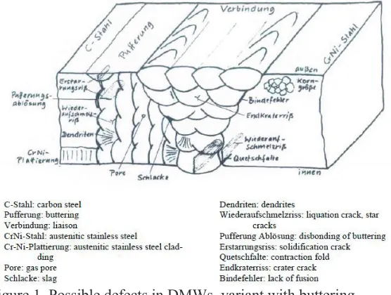
chemistry condition. Lack of fusion, which is due to welding process, can be occasionally found at fusion line between weld and base material. Such manufacturing indications (like also pore or slag intrusion and worm hole) are not challenging the structural integrity of the weld if they are embedded (no contact with medium), isolated and limited in length. No growth of such indication has been experienced. The listed potential defects are represented in Figure 1.
Figure 1. Possible defects in DMWs, variant with buttering
During service,the only active degradation mechanism which has been observed up to now in DMW in NPP field was stress corrosion cracking due to primary water (PWSCC) only in the case of the DMW with Ni-based alloy variant with contact with the medium (the German DMW variant with Ni-alloy protected by stainless steel root or cladding has not been affected by corrosion). Observed cracks have been predominantly axial oriented. Long part-trough wall circumferential cracks are not likely, and were mainly found in combination with alloy 600 base materials. In addition, industry generic analyses have shown that adequate time exists between leakage detection and growth to critical flaw size, allowing a safe shut down of the plant. DMW issues related to corrosion are summarized in MRP-113NP.
According to the TECNATOM contribution following ASME, for the repair of DMWs showing defects during ISI, the preferred method is the application of a Weld Overlay (WOL). The WOL consist of several layers of a SCC resistant material applied on the outside surface of the affected welds. In the case of the Full Structural Weld Overlays (FSWOL), the thickness is calculated to structurally replace the original weld, i.e., it does not rely on the original weld for strength. In addition, the FSWOL introduces a compressive residual stress distribution at the inner surface of the weld, inhibiting the development of further SCC. For this reason, FSWOL have been pre-emptively applied as a PWSCC mitigation measure to the Pressurizer nozzle to safe-end Alloy 82/182 DMWs in most of the Spanish plants. However, WOLs may invalidate the original LBB analysis due to the changes in geometry of the original weld, crack morphology and material properties upon which the original LBB analysis was based. Updating the LBB analysis entails the calculation of the leakage and fracture mechanics margins to ensure that the general design condition is met.
Sub-task 2 Residual stress in DMWs
parameters. Welding process was manual for existing running plants. For newest plants, automatic welding process is given preference.
An exhaustive description of the weld residual stress measurement has been given by JRC. Among the various methods for the determination of residual stresses, we have two techniques categories, the (semi) destructive ones based on strain relaxation methods during cutting or drilling. Example of strain gauge based relaxation methods are crack compliance (1-D, high penetration), Surface hole drilling, Ring core method (both 2-D, rather surface). The second category corresponds to the non-destructive techniques : diffraction, magnetic, acoustic, optical techniques. Concerning X-ray diffraction techniques, the laboratory X-ray diffraction can investigate the near surface of a component. The high energy X-ray diffraction – synchrotron allows for deeper penetration, high resolution. Neutron diffraction provides non-destructive (semi-non-destructive) 3-dimensional measurements of residual stress from the bulk of crystalline materials at reasonable spatial resolution. Measurements in steel up to about 2-3 cm depth are possible at high performance facilities. Neutron diffraction is sensitive to grain size effects and non-homogeneities in the microstructure. Mock-up manufactured within Multimetal will be investigated with this last method at JRC-Petten.
Difference of thermal expansion coefficients of adjacent metal will induce tensile stress in one metal. After PWHT, the residual stresses parallel to the welding direction tend to be tensile in the material with the higher coefficient of expansion, and compressive in the material with the lower coefficient of expansion, with a discontinuity in the stress field at the interface. Nickel based fillers (Inconel) produce welds with lower thermal expansion rates than the stainless steel fillers. The yield mismatch M can be defined as the ratio of the yield strength of the weld to the yield of the adjacent base material. In DMW we have undermatch considering the ferritic base material and the weld (Sy W / Sy BM < 1) and overmath for the couple weld and austenitic base material. Under mechanical loading the undermatch effect concentrates strain and high triaxiality along the ferritic interface, the austenitic material being the weakest one, concentrates the hardening effects during loading. Under thermal loading (like thermal shocks), there is no effect of the mismatch of yield stress on J the mismatch of thermal expansion coefficients induces a secondary loading and the displacement loads are filtered by the stainless steel part. Generally residual stresses seem to be moderate when measured at elevated temperatures, whereas at the room temperature higher residual stress peak was recorded.
Participants have summarized some general measures to prevent or mitigate the residual stresses at the surface in contact with LWR medium. Requirement for the different heat treatment related to welding (preheating, postheating, postweld heat treatment, requirement for bi-metallic weld are given in the KTA rules.Grinding of surface induced locally tensile stresses extending locally through the thickness depending on the grinding process. The residual stress induced by grinding is a local stress which can reach the yield strength at the ambient temperature. The effect of grinding during buttering preparation on the stresses is affected by post welding heat treatment and by the final welding. According to the KTA3201.3 Chapter 5.1 Weld design: “When machining surfaces care shall be taken to ensure that only little heat is transferred into the component, the input of inadmissible impurities (halogens), e.g. through the use of grinding tools, is avoided. In the case of austenitic components containing reactor water which are subject to operating temperatures equal to or exceeding 200 °C in BWR plants, a qualification of the machining procedures is required with the aim of ensuring for the fluid-wetted surface, in addition to the requirements above only slight cold working in the near-surface area, and only slight strain hardening in the surface area.
during manufacturing and operation. EDF-Energy describes their participation to the international weld residual stress round robin project which was conducted by the U.S. NRC. In this project the weld residual stresses of a pressurizer surge nozzle DMW mock up were computed by using finite element methods, finally results were compared to measurement. The mock-up consisted of a SA-105 carbon steel nozzle, a TP316 Stainless steel safe-end and pipe. Alloy 82 was used as filler metal. The intention of this round robin was to refine computational procedures and categorize uncertainties in weld residual stress predictions. Summary of EDF-Energy is reproduced here: “Overall, both the performance of the measurements and the agreement between measurements and simulations are impressive. The predicted residual stresses show little sensitivity to mesh design and thermal modelling strategy over the outer 75% of the dissimilar metal weld. The predicted axial stresses show relatively little sensitivity to the material hardening model over the outer 75% of the dissimilar metal weld. The predicted hoop stresses show a clear sensitivity to the material hardening model over the outer 75% of the dissimilar metal weld. The most accurate hoop stresses are predicted using mixed hardening constitutive behaviour, where the response of Inconel weld metal is based upon that of solution treated weld metal. Isotropic hardening leads to conservative predictions of hoop stress, and non-linear kinematic hardening to non-conservative predicted hoop stresses, if both models are based upon the response of solution treated weld metal. Kinematic hardening based upon the response of multi-pass (fully hardened) weld metal also leads to a slightly conservative prediction of hoop stresses, making this a good pragmatic approach to use when limited materials data are available. Predicted stresses near the inner wall do not show clear trends with material model, and appear to be sensitive to other solution variables. Overall, the predicted axial stresses are more tensile than the measurements near the inner wall, and less tensile than the measurements between 50% and 90% of the wall thickness near the outer wall. The measurements have a larger through-wall bending component than the simulations. The reasons for this have not yet been established”
The second example is part of the European project STYLE – Structural Integrity for Lifetime Management. Within the framework of STYLE a case study was launched to assess the capability of finite element weld residual stress simulations. The mock-up chosen for this case study is a stainless steel 316L pipe connected to a carbon steel A508 Class 3 pipe by means of an Alloy 52 GTAW narrow gap weld which is representative for PWR primary circuit piping. A 2D axisymmetric uncoupled transient thermal and mechanical finite element analysis was used to calculate the stresses. The layout of this model as well as the calculated (AREVA) and measured through wall stress evolutions in the DMW after welding were in good agreement. VTT performed a comparison of the weld residual stress definition recommended in codifications for assessment of structural integrity of component with defect for several pipe dimensions. The study was carried out within a national SAFIR programme was concerned with welding process induced residual stress distributions in NPP reactor circuit component DMW welds. The covered residual stress definition procedures were the ASME recommendations, the British Standard BS 7910: 1999, the R6 Method Revision 4, the SAQ handbook, the SINTAP Procedure,the API 579 procedure and the FITNET Procedure. In the study the weld residual stress distributions were calculated with the above mentioned 7 procedures for welds in representative small, medium and large NPP reactor circuit pipes in Finnish BWR NPP units.
Information were gathered on the effect of residual stress fields due to welding on fracture testing procedure: residual stress is reduced after specimen cutting, see MPA, and cracks can be deviated during pre-fatiguing at low K-level, however the tearing resistance of tough joints seem not to be affected at usual LWRs service temperatures.
Sub-task 3 Overview on regulatory integrity assessment of DMWs including LBB
(covered by EDF-Energy, French codification RCC-M (design) and RSE-M (service) covered by EDF, German KTA standard covered by AREVA. European procedures have been also published covering DMWs assessment (SINTAP / FITNET), as well as Russian procedure (for LBB purpose).
The ASME rules and KTA standard are mandatory: The ASME rules are also linked to the regulation. The KTA standards are published by the German authorities and are therefore required by federal regulation and thereby made into law. The RCC-M and RSE-M are codifications which are mainly accepted by the safety authorities, however, they are not equivalent to harmonized standards. An overview of DMW defect assessment codified procedure shows that a detailed guidance is given in the R6-code following a three level assessment (engineering assessment method up to numerical approach). Acceptance criteria for defect in DMW region can be obtained from evaluation mainly based on modified limit load assessment according to ASME XI and KTA 3206, the last dealing also with break exclusion assessment and allowing for a more detailed assessment using a numerical approach. Specific procedures for integrity assessment of flaws in DMWs with acceptance criteria are available in ASME XI App. C (for existing flaws, or for flaws occurring during operation) and KTA 3206 (for postulated flaws, for existing flaws from manufacturing, assessment of flaws occurring during service is excluded and must be handle separately and is submitted to the agreement of the inspection services and safety authorities.). Specific procedures for integrity assessment of flaws in DMW are available in the R6-code, however, the acceptance criteria are not defined: no structural or safety factors are imposed, the user has to perform a parameters study to investigate the weight of the different parameters. Other codes or standards have no hint for flaw assessment in DMWs, and such assessments are per-formed on a case by case study, considering the State of the Art. Concerning LBB, the German KTA 3206 covers also DMWs, the required data being tensile and yield strength for the material fulfilling the KTA requirement. Limit load based solutions are used considering the weakest base material in term of flow stress. Welding residual stress are discarded for ductile fracture assessment. Evaluation the J-contour integral were developed for homogeneous material, but none of the solution is explicitly proposed for usage with DMW. Following the U.S. rules, a direct application of J estimation schemes is not necessary for the evaluation of part-through-wall cracks when the ductile tearing failure mode is applicable. In this case a modified limit load criterion applies.
Sub-task 4 State of the art in experimental procedures for mechanical and fracture toughness testing
microstructure sampled by the crack tip as well as the constraint conditions due to mismatch effects. Therefore, further investigations are needed in order to define the best practice in fracture mechanical tests and their analysis for DMWs. The sample preparation as well as the orientation relative to the fusion line are crucial parameters that need to be addressed prior to testing. During pre-fatiguing, it is also important to keep a straight crack growth.
CONCLUSION
Recommendations on crack locations for fracture toughness specimens cut from a DMW narrow gap mock-up were made based on consortium experiences:
• lowest tearing resistance (J-R) is at the fusion line. The crack deviates to the lowest strength area driven by the strength mismatch. It is possible that the crack grows into a region which does not have the lowest intrinsic fracture toughness. Proposition for notch locations: at fusion line (ferritic / Inconel), +0.5mm (in the inconel weld metal) and -0.5 mm (in the ferritic HAZ) from fusion line.
• AREVA/CEA: the weakest area for ductile failure mode is the weld metal with a plasticity/damage concentration i.e high stress triaxiality (ratio of hydrostatic stress / equivalent stress) , therefore the notch location is set to the fusion line (ferritic steel/Inconel), and to 0.5mm and 1mm from FL (in the inconel weld).
A number of items need to be addressed prior testing in addition to procedure described in the standard (ASTM E1820). Following items were identified: the crack propagation path must be clearly identified and some recommendation must be provided on the acceptable deviation from the initial crack plane. The determination of relevant eta factor equation for DMW: this unit-less parameter is used to estimate the potential energy released rate during the test for different specimen geometries. Existing equations are available only for homogeneous specimen. A complete compendium must be developed to take into account the mismatch effects and the size and the location of the crack with respect to the interface. Post-test fractography and metallographic analysis of the cross-section must be performed to determine the real location of different material zones in the vicinity of the crack and to evaluate the size of the stretch zone.
ACKNOWLEDGEMENT
NOMENCLATURE
BWR Boiling Water Reactor CDZ Carbon Depletion Zone
CGHAZ Coarse Grain Heat Affected Zone
CS Carbon steel
DMW Dissimilar Metal Weld
EU/EC European Union / Commission
FE Finite Element
FL Fusion Line
FSWOL Full Structural Weld Overlays HAZ Heat Affected Zone
LBB Leak-Before-Break LWR Light Water Reactors MNZ Martensitic Narrow Zone NPP Nuclear Power Plant
PWHT Post Welding Heat Treatment
PWSCC Primary Water Stress Corrosion Cracking SEN(B/T) Single-Edge-Notch Bend/Tension
Sy Effective yield strength UT Ultrasonic Testing
WP Work Package
WOL Weld Overlay LAS Low Alloy Steel
M Mismatch
REFERENCES
[MULTIMETAL] P Karjalainen-Roikonen, E.Keim, P.Gilles, S.Blasset “EC FP7 Structural performance of MULTI-METAL component project overview”, PVP2013-97574
[ASTM] ASTM Standard ASTM E 1820
[R6] R6, Assessment of the integrity of structures containing defects, Revision 4, 2001, with Amendment, 2011, EDF Energy Nuclear Generation Ltd.
[ASME] ASME Boiler and Pressure Vessel Code Section XI, 2010 Edition
[RCC-M] French design construction code for NPP,
AFCEN, 2010 Edition
[RSE-M] French code for operating NPP,
AFCEN, 2010 Edition
[KTA] Safety Standards KTA 3206: “Demonstration of Break Preclusion for Pressure Retaining Components in Nuclear Power Plants” 2014-11
[BIMET] G.Chas, C.Faidy, R-C. Hurst: “Structural integrity of bi-metallic components program (BIMET): fracture testing of bi-metallic welds”, Paper 8585, Proc. ICONE 8, April 2000, Baltimore USA
[ADIMEW] C.Faidy, G.Martin, N.Taylor, A.Youtsos, D.Katsareas, H.Keinänen, A.Laukkanen, J.Wintle, A. Sherry, D.Lidbury, N.Safa, M-F. Cipière, P.Gilles, S.Chapuliot, Y.Kaiser and Gy.Lenkey: “Assessment of aged piping dissimilar weld integrity” ADIMEW Synthesis report, Contract FIKS-CT-2000-00047. European Commission, January 2004. 45p
[STYLE] T.Nicak, E.Keim “STYLE project overview”, Proceedings of the ASME 2010 Pressure Vessels and Piping Conference, PVP2010-25389, Washington, USA
[MPA] M.Büttner, M.Seidefuß, D.Krätschmer, E.Roos: “Experimental and damage mechanical investigation of crack propagation in dissimilar welds”, 37. MPA-Seminar, 6-7 October 2011, Stuttgart Germany
[MRP-113NP] MRP-113NP, “Material reliability program: alloy 82/182 pipe butt weld safety assessment for US PWR plant design” non-proprietary version, EPRI, 2004
[Dissimilar] Consortium Dissimilar, “Guidelines for generating array ultrasonic procedures for the inspection of dissimilar/austenitic welded components”, TSB Project No: TP11/MFE/6/I/AA058J, 2011
[Smith] M C Smith, O Muranski, A Goodfellow, E Kingston, P Freyer, S Marlette, G M Wilkowski, B Brust and D-J Shim, The impact of key simulation variables on predicted residual stresses in pressuriser nozzle dissimilar metal weld mock-ups. Part 2 – comparison of simulation and measurements, ASME PVP 2010, Bellevue, WA., 18-22 July 2010, PVP2010-26025 (2010).