Reduction of Harmonics using 12-pulse
AC-DC Converter in Vector controlled
Induction Motor Drives
Harish H S1, Sujith T2
M Tech Student (CAID), Department of EEE, B.N.M Institute of Technology, Bengaluru, Karnataka ,India1 Assistant Professor, Department of EEE, BNM Institute of Technology, Bengaluru, Karnataka, India2
ABSTRACT: The Power electronic devices are not linear loads, they are non-linear loads: the nature of non-linear loads of these switching devices results in current harmonic injection into ac mains by polluting power quality at PCC. This current harmonic reduction is achieved by adopting multi-pulse converters. In this paper, a novel technique of autotransformer with a diminished KVA rating is exhibited forthe current harmonic reduction in twelve pulse ac-dc converter fed controlled induction machine drives. Twelve pulses based amendment novel harmonic mitigator fit for smothering fifth, seventh, and eleventh in the input supply current are presented. The proposed autotransformer harmonic mitigator is presented and the simulation model is developed in MATLAB.
KEYWORDS: Autotransformer, Vector controlled induction motor drive, harmonic mitigator, multi-pulse ac-dc converter, MATLAB.
I. INTRODUCTION
Induction motors have been considered as a universally accepted choice in industrial applications due to their advantages such as improved efficiency, energy savings, ruggedness and low cost. The DC motors have been used for variable speed drives because of their flexible characteristics. With the growth of the power electronic converters, the majority of the dc drives are being replaced by variable frequency induction motor drive. To achieving the high-performance control of induction motor drives are generally operated in vector control [1], and this has been accepted widely in industry. These induction motors drive operated by vector controlled are fed by an uncontrolled multi-pulse ac-dc converter which results in the injection of current harmonics into the supply system. The AC–DC power converter feeding power to the VCIMD consists of a 6-pulse diode bridge rectifier, an energy storage element at dc link, and a three-phase voltage source inverter (VSI). The diode bridge rectifier suffers from operating problems such as poor power factor, injection of harmonic currents into the AC mains, equipment overheating due to harmonic current absorption, low rectifier efficiency, input AC mains voltage distortion, and malfunction of sensitive electronic equipments due to electromagnetic interference (EMI). Various methods based on the principle of increasing the number of pulses in AC–DC converters to mitigate current harmonics [2]. These methods use two or more converters where the harmonics generated by one converter are canceled by another converter through proper phase shift [3].These autotransformer based schemes considerably reduce the size and weight of the transformer. Autotransformer-based multi-pulse AC–DC converters have been introduced for reducing the total harmonic distortion (THD) of the AC mains current [4]. To provide equal power sharing between the diode bridges and to achieve good harmonic cancellation, interphase transformers are needed [5][6]. The proposed multi-pulse ac-dc converters those are suitable for retrofit feed vector controlled induction motor drive (VCIMD) [7].This proposed multi-pulse ac-dc converter results in the elimination of 5th, 7th, 11th, 13th harmonics. It results in near unity power factor operation in the wide operating range of the drive with the THD of ac mains current always less than 5%.
proposed harmonic mitigator are resulted in elimination of the fifth, seventh, eleventh and thirteen order harmonic distortion.
II. DESIGN OF PROPOSED 12-PULSE AC_DC CONVERTER BASED HARMONIC MITIGATOR
The required minimum phase shift for harmonic elimination is given by
Phase shift= °
Fig:1 Six-pulse diode bridge rectifier-fed vector-controlled induction motor drive.
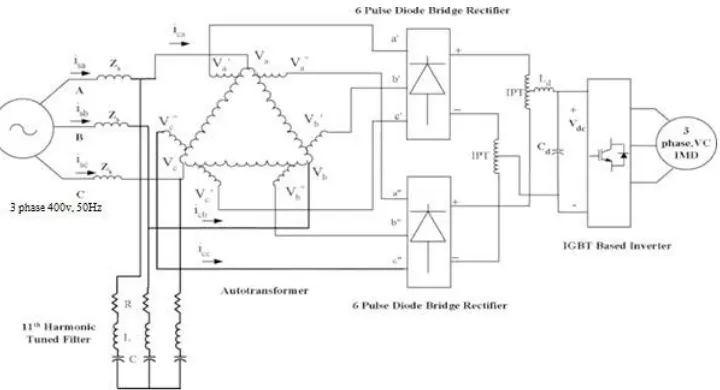
This section deals with the autotransformer arrangement for the proposed 12-pulse ac-dc converter based harmonic mitigator referred as topology “A” as shown in fig:2.
A. Design of Autotransformer for Twelve-pulse Converter
To achieving 12-pulse rectification, the following conditions have to be satisfied
a) The phase shift between the two sets of voltages may be either 0° and 30° or ±15° out of phase with respect to each other. Here ±15° phase shift is used to reduce the size of magnetics.
b) The magnitude of these line voltage should be equal to each other to result in symmetrical pulses and reduced ripple in dc output voltage.
From the supply voltages, two sets of three-phase voltages (phase shifted through +15° and -15° ) are produced. The number of turns required for +15° and -15° phase shift are calculated as follows. Consider phase “a” voltages as
Va׳= Va + K1∗ Vca–K2∗ Vbc (1)
Va״ = Va- K1* Vab + K2* Vbc (2)
Assume the following set of voltages:
Va= V∠0°, Vb = V∠-120°, Vc = V∠120° (3)
Similarly
Va׳= V∠15°,Vb׳= V∠-105°,Vc׳= V∠135° (4)
Va״=V∠-15°,Vb״=V∠-135°,Vc״= V∠105° (5)
Where V is rms value of the phase voltage.
By using above equations, K1 and K2 can be calculated. These equations result in caivilation of K1 and K2 for the desired phase shift in autotransformer. The voltage equation of phase shifted for phase “a” are
Va׳= Va+ 0.0227 Vca –0.138 Vbc (6)
Va״ = Va- 0.0227 Vab + 0.138 Vbc (7)
The interphase transformers are used to ensure that the independent operation of diode bridge rectifier groups. B. Design of passive tuned filter.
To improve the power quality, a passive shunt filter has been Designed in accordance with IEEE Standard 1531-2003.
Fig 3. Shows the Proposed harmonic mitigator fed VCIMD with passive filter connected at the ac mains. Design equation for filter.
The passive filter is designed by the following equations. The impedance branch of the filter is given as
Z = R+j(ωL− ) (8)
The resonance frequency can be written as
fn =
{ ( ) }
(9) The inductor and capacitor impedances for th harmonic areXln = nωL and Xcn = 1/(nωc).
Fig. 3. Proposed harmonic mitigator fed VCIMD with Passive filter.
III. VECTOR-CONTROLLED INDUCTION MOTOR DRIVE
The Indirect vector controlling technique is widely used in industrial field for controlling induction motor. Fig 1 shows the diagram of anindirect method of vector controlled induction motor drive. The power circuit configuration consists of a diode bridge front end rectifier and an SVPWM inverter. The torque component Iqs current is generates from the
speed control loop. In indirect technique vector control, flux control is aneed in closed loop. Flux is constant in the region of constant torque. The component Ids is obtained from the rotor flux. The speed PI controller compares reference speed (ωr*) with the motor speed (ωr) and torque is generated from the speed control loop. After limiting
Torque to a suitable value reference torque T* is obtained.
The flux control signal with T* are given to the vector controller, it calculates torque component and flux angle.
Ids* = imr + τr(
∆
∆ ) (8)
i
*qs=
∗
( ∗ )
(9)
ω2* =i*qs/(τr×imr) (10)
These currents (ids* and iqs*) components are converted to stationary frame reference by calculating rotor flux angle as
the sum of the value of slip angle and rotor angle. The currents are converted to stationary reference frame of three
phase currents. By using Inverse Park transformation abc coordinates are transformed to the α and β voltages
coordinates and output is fed to the SVPWM which provides gating signals to the different switches of Voltage source inverter to develop voltages. Provide these voltages to the induction motor to develop the torque at a given speed.
V. MATLAB BASED SIMULATION
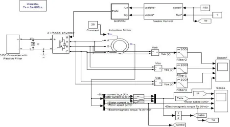
The fig.4. Shows six pulse diode bridge rectifier fed VCIMD Matlab model simulation.
Fig. 6.Shows the AC/DC converter connection diagram.
VI. RESULTS AND DISCUSSION
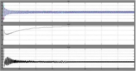
The proposed harmonic mitigators along with vector controlled induction motor have been simulated to demonstrate the performance of the proposed system.Fig. 7. Shows the dynamic response of a Twelve-pulse diode bridge rectifier fed VCIMD. It consists of the rotor speed “ωr” (in radial/sec), three phase currents isabc and electromagnetic torque “Te
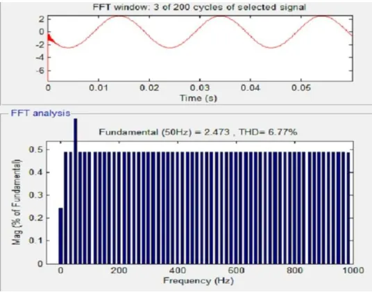
(in N/M). The total harmonic distortion for six pulse rectifier is 12.74%. There is a need for improving the power quality indices at the AC mains using some harmonic mitigators where can easily replace the existing six-pulse converter.Fig.8. shows the supply current waveform along with it’s harmonic spectrum at full load. The Total Harmonic Distortion for proposed twelve pulse rectifier is 6.77% compared to Six pulse converter configuration the Total Harmonic Distortion at the supply current side will be reduced.
Fig. 8.Shows the supply current waveform along with its harmonic spectrum at full load for six pulse Diode bridge rectifier fed VCIMD.
Fig. 9.Shows the supply current waveform along with its harmonic spectrum at full load for proposed twelve pulse Diode bridge rectifier fed VCIMD.
VII. CONCLUSION
the capability of improvement Total Harmonic Distortion of the supply current. Therefore the proposed mitigator can replace the existing 6-pulse converter*without much alteration.
APPENDIX
MOTOR AND CONTROLLER SPECIFICATION Motor Parameters
Three-phase squirrel cage induction motor -5.4HP(4KW), four-pole, delta configuration 400V, 50Hz, Rs = 1.405Ω, Rr
= 0.228Ω
Lm =0.1722 Henry, J = 1.31kg-m2.
Control Parameters
DC link Parameters: Ld = 0.6mH, Cd = 3200μF.
REFERENCES
[1] P. Vas, Sensorless Vector and Direct Torque Control. Oxford, U.K.: Oxford Univ. Press, 1998.
[2] D. A. Paice, Power Electronic Converter Harmonics: Multipulse Methods for Clean Power. Piscataway, NJ: IEEE Press, 1996. [3] S. Choi, P. N. Enjeti, and I. J. Pitel, “Polyphase transformer arrangements with reduced kVA capacities for harmonic current reduction in rectifier type utility interface,” IEEE Trans. Power Electron., vol. 11, no. 5, pp. 680–689, Sep. 1996.
[4] D. A. Paice, “Multipulse converter system,” U.S. Patent 4 876 634, Oct. 24, 1989. [5] P. W. Hammond, “Autotransformer,” U.S. Patent no. 5 619 407, Apr. 8, 1997.
[6] S. Hansen, U. Borup, and F. Blaabjerg, “Quasi 12-pulse rectifier for adjustable speed drives,” in Proc. IEEE APEC Conf., 2001, pp. 806–812. [7] G. R. Kamath, B. Runyan, and R. Wood, “A compact autotransformer based 12-pulse rectifier circuit,” in Proc. IEEE IECON Conf., 2001, pp. 1344–1349.
[8] IEEE Guide for Application and Specification of Harmonic Filters, IEEE Std. 1573, 2003.
[9] D. A. Gongalez and J. C. Mccall, “Design of filters to reduce harmonic distortion in industrial power systems,” IEEE Trans. Ind. Appl., vol. IA-23, no. 3, pp. 504–511, May/Jun. 1987.
BIOGRAPHY
Harish H S received his Bachelor of Engineering from P.E.S college of Engineering, Mandya, Karnataka, India. Currently perceiving Master of Technology in Computer Application in Industrial Drives in B.N.M Institute of Technology, Bengaluru, Karnataka, India. His area of interest includes Power electronics & Drive.