IJEDR1402061
International Journal of Engineering Development and Research (www.ijedr.org)1648
Abstract - This paper proposes an algorithm for CT saturation by behavior of distorted secondary current. The purpose of current transformer is to convert the primary current in the secondary circuit in a most accurate way. However, during fault conditions CT gets saturated. Some reasons due to current transformer (CT) can saturate like: attempting to mal operation of CT, heavy burden apply on the secondary side or due to transient DC offset fault current. Fortunately, due to the ever changing nature of the alternating current, even if the CT is pushed into saturation, in each cycle of the waveform, there are times during which magnetic core comes out of saturation. During these times the transformation of CT is correct but as soon as the magnetic core enters in to deeper saturation the current transformer will start exhibiting enormous errors. Thus, the key to correct these errors is to detect the instant when the saturation sets in and the instant when saturation ends. The idea of linear predictive coding (an autoregressive model) is to express the nth sample of signal as a sum of the past K known weighted samples. When analyzing disturbance signals the optimal prediction coefficients will change for each system state (e. g. pre-fault, fault and post fault) and therefore must be estimated continuously.The method for CT saturation detection that has been simulated is, CT saturation detection using linear predictive coding, in this method can successfully detect the onset of CT saturation. The test results clearly indicate that the proposed algorithm successfully detects the interval of saturationKeywords - Current Transformer Saturation, linear predictive method.
________________________________________________________________________________________________________
I. INTRODUCTION
Current transformers secondary current distorted due to mal operation of CT, the current transformer is used for transform the primary current in secondary circuit, CT play a vital role in any protective system in transmiss ion line. The healthy operation of the relay entirely depends upon the of the CT to transform the fault current waveforms. In a normal condition, the CT would operate good degree of accuracy and However, i n s o m e s i t u a t io n CTs facing p r o b l e m s. due of this CTs gets saturate, during the fault condition i.e. t he ho l e p rot ect i ve s ys t e m i nfl o wi ng f a ul t c urr e nt. Thus, researchers are always finding new technique better methods of mitigating the effect of CT saturation. If we are in mitigating these problems than it can be cost saving due to CT saturation problem. In electrical transmission s y s t e ms, due to current transformer saturation relays behave as in abnormal condition. In this paper, investigates the transient behavior of current transformer, these problems may cause severe mal-operation o f p r o t e c t i o n to v a r i o u s p l a n t s t hus c a u s i n g d a ma g e s the critical electrical equipment. To address this problem, the IEEE guide for the application current transformer (IEEE standard C37.110 and C57.13-1993) contains steps to avoid the effects of AC and DC current transformer saturation. Unfortunately, many of these steps result in impractically large current transformers, which are economically not acceptable. These papers implement the CT saturation detection using linier predictive coding method.
II. METHODS OF MITIGATION OF CT SATURATION
Some of the methods which can be used for mitigate CT saturation are as follows 1. Construction of CT acco r d i n g t o IEEE s t a n d a r d s spe c if ic a t io n to avoid Saturation 2. Replacement of conventional CT by optical current sensor
IJEDR1402061
International Journal of Engineering Development and Research (www.ijedr.org)1649
Fig:1 Current Transformer saturation simulation circuit Circuit description
A current transformer (CT) is used to measure current in a shunt inductor connected on a 220 kV, 50 Hz network. The CT is rated 2000 A / 5 A, 25 VA. The primary winding which consists of a single turn passing through the CT toroidal core is connected in series with the shunt inductor rated 69.3Mvar,69.3kv.The secondary winding consisting of 1*2000/5 = 400 turns is short circuited through a 1.0 ohm load resistance.
IV. EFFECT OF TRANSIENT BEHAVIOR OF CT’s ITS SATURATION
CT performance is affected significantly by the dc component of the ac current. When a current change occurs in the primary ac system, one or more of the three-phase currents may contain some dc offset [1]. This dc results from the necessity to satisfy two conflicting requirements that may occur: (1) in a highly inductive network, the current wave must be near maximum when the voltage is at or near zero and (2) the actual current at the time of the change, which is determined by the prior networks conditions. During asymmetrical faults, the fault current can be represented by two parts, namely the dc and ac components follows:
…….. (1)
The total fault current can be rewritten as: ( )
( ) ……..(2)
Below Figure shows the shaded volt-time area produced by asymmetrical fault current. Here If is the magnitude of the fault current in the secondary, Zb is the burden impedance, and L/R is the time constant of the primary fault circuit. The sine wave and exponential components of the wave are shown dashed for comparison. The sine wave and the exponential represent the asymmetrical fault in equation. The plot shows the change of burden voltage with the time.The volt-time area of the asymmetrical fault is increased compared to the normal sine wave and hence will affect the performance of the CT[1].
IJEDR1402061
International Journal of Engineering Development and Research (www.ijedr.org)1650
Fig: 3 Primary current due to fault Current with AC and DC components
Fig:4 Secondary saturated current due to AC and DC Components
V. CT SATURATION DETECTION BY LINEAR PREDICTIVE CODING
In most protective relays, operating decisions are based on the RMS value of the fault current at the S e c o n d a r y of t h e CT. If the signal supplied by the CT is distorted by saturation, the sensed RMS value will be much lower than the actual fault current, which may delay or even prevent tripping of the relay. This may leads to a loss of coordination with other relays in the system. Detecting the start and end of the saturation is an important step before correcting the secondary current, so that algorithm for correction will work only during saturation and by pass the secondary current when there is no saturation[2]. In this paper right approach are presented to detect the CT saturation, Method for detecting CT saturation is
CT saturation detection by linear predictive coding method
The idea of linear predictive coding (an autoregressive model) is to express the n th sample of signal as a sum of the past K known weighted samples.
̂( ) ∑ ( ) ... ………(1)
The prediction error εx can be expressed as
( ) ( ) ( ) ... ……… (2)
The prediction coefficients ak with k ∈ {1,..., K} are calculated by solving a least square problem that minimizes with a =[a1,..., ak].
( ) ∑ ( )
... ………(3)
IJEDR1402061
International Journal of Engineering Development and Research (www.ijedr.org)1651
Fig 5 Differences at saturation occurrenceAssuming the DC component of a fault current is positive the error signal will always be negative each time saturation occurs (Above Fig.)[4].
̂ ... .……(4)
To detect saturation occurrence precisely a model order of K =6 was chosen. Depending on the sign of the DC component either negative or positive error signals
{
| ̂ | ̂ | ̂ | ̂
…….(5) are compared with the threshold value
̂ ( ) ………... (6)
An impulse in εis is greater than the threshold value indicates an abrupt change in signal parameters i. e. saturation occurs. The advantage using this method is the higher number of considered samples K and therefore a higher robustness to noise [5].
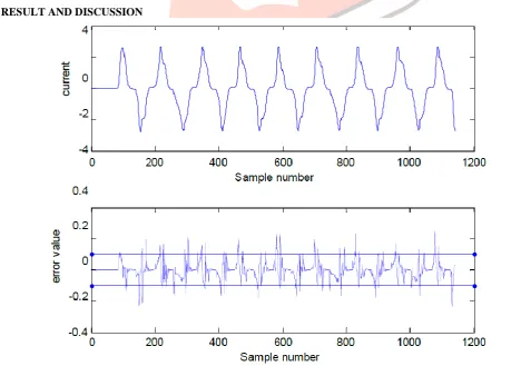
VI. RESULT AND DISCUSSION
IJEDR1402061
International Journal of Engineering Development and Research (www.ijedr.org)1652
error value is more than threshold indicates saturation.REFERENCES
[1] N. Villamagna and P. A. Crossley, “A CT saturation detection algo-rithm using symmetrical components for current differential protection,” IEEE Trans. Power Del., vol. 21, no. 1, pp. 38–45, Jan. 2006.
[2] N. Locci and C. Muscas, “A digital compensation method for improving current transformer accuracy,” IEEE Trans. Power Del., vol.15, no. 4, pp. 1104–1109, Oct.2000.
[3] D. C. Yu, J. C. Cummins, Z. D. Wang, H. J. Yoon, and L. A. Kojovic, “Correction of current transformer distorted secondary currents due to saturation using artificial neural networks,” IEEE Trans. Power Del. ,vol. 16, no. 2, pp. 189–194, Apr. 2001.
[4] Y. C. Kang, U. J. Lim, S. H. Kang, and P. A. Crossley, “Compensation of the distortion in the secondary current caused by saturation and remanence in a CT,” IEEE Trans. Power Del., vol. 19, no. 4, pp.1642–1649, Oct. 2004. [5] IEEE Guide for the Application of Current Transformers Used for Protective Relaying Purposes,ANSI/IEEE C37.110
Std.
[6] IEEE C57.13-1993 Standard Requirements for Instrument Transformers.
[7] Y. C. Kang, U. J. Lim, S. H. Kang, and P. A. Crossley, “Compensation of the distortion in the secondary current caused by saturation and remanence in a CT,” IEEE Trans. Power Del., vol. 19, no. 4, pp. 1642–1649, Oct. 2004. [8] Howard Demuth, Mark Beale, Martin Hagan “Neural Network Toolbox™ 6 User’s Guide”, March 2008, Tenth
printing
[9] Fundamentals of power system protection by Y.G.PYTHANKAR, S.R.BHIDE
[10] J.L. Blackburn and T.J. Domin,, protective Relaying: Principles and Application 3rd ed., New York: CRC press,2007. [11] J.Pan, K.Vu, and Y.Hu, “An efficient compensation algorithm for current transformer saturation effects”
“IEEE Trans. Power Delivery,vol.19,no. 4, pp. 1623-1628,Oct. 2004
[12] C.-S.Yu, Z.-S. Wu, and J.-A Jiang, “An adaptive mimic filter based algorithm for detections of CT saturation,” Proc. IEEE General meeting, Canada, July 2009.
[13] W.Rebizant and D.Bejmert, “Current transformer saturation detection with genetically optimized neural networks, “IEEE Trans. Power Delivery,vol.22,no. 2, pp. 820-827,Apr.2007