R E S E A R C H
Open Access
Non-Regenerative Multi-Antenna Multi-Group
Multi-Way Relaying
Aditya Umbu Tana Amah
1*and Anja Klein
2Abstract
We consider non-regenerative group way (MGMW) relaying. A half-duplex non-regenerative multi-antenna relay station (RS) assists multiple communication groups. In each group, multiple half-duplex nodes exchange messages. In our proposal, the required number of communication phases is equal to the maximum number of nodes among the groups. In the first phase, all nodes transmit simultaneously to the RS. Assuming perfect channel state information is available at the RS, in the following broadcast (BC) phases the RS applies transceive beamforming to its received signal and transmits simultaneously to all nodes. We propose three BC strategies for the BC phases: unicasting, multicasting and hybrid uni/multicasting. For the multicasting strategy, network coding is applied to maintain the same number of communication phases as for the other strategies. We address transceive beamforming maximising the sum rate of non-regenerative MGMW relaying. Due to the high complexity of finding the optimum transceive beamforming maximising the sum rate, we design generalised low complexity transceive beamforming algorithms for all BC strategies: matched filter, zero forcing, minimisation of mean square error and BC-strategy-aware transceive beamforming. It is shown that the sum rate performance of non-regenerative MGMW relaying depends both on the chosen BC strategies and the applied transceive beamforming at the RS.
Keywords:Multi-way relaying, Non-regenerative, Multi-antenna, Analog network coding, Transceive beamforming
Introduction
Two-way relaying is a spectrally efficient protocol to establish bidirectional communication between two half-duplex nodes via a half-half-duplex relay station (RS) [1-3]. It was shown in [1,3] that two-way relaying outperforms the traditional one-way relaying due to its smaller num-ber of communication resources. In two-way relaying, two communication phases are needed. The first phase is the multiple access (MAC) phase where the two com-municating nodes send their data streams simulta-neously to the RS. The second phase is the broadcast (BC) phase where the RS sends the processed signals simultaneously to both nodes. Consequently, the nodes need to cancel their self-interference.
Regarding the signal processing at the RS, it can be either regenerative, cf. [1,2] or non-regenerative, cf. [1,3]. A regenerative RS regenerates (decodes and
re-encodes) the data streams of all nodes while a non-regenerative RS performs linear signal processing to the received signals and transmits the output to the nodes.
The use of multiple antennas can improve the spectral efficiency and/or the reliability of communication net-works [4,5]. For two-way relaying, a multi-antenna RS that serves one bidirectional pair was considered in [6-8] for a regenerative RS and in [3,9-11] for a non-regenerative RS. For the non-non-regenerative case, while [3,9] assume multi-antenna nodes, [10,11] assume single antenna nodes. Their works consider optimal transceive beamforming at the RS maximising the sum rate as well as linear transceive beamforming based on Zero Forcing (ZF) [3,9-11], Minimisation of Mean Square Error (MMSE) [3,9,10], Maximisation of Signal to Noise Ratio (MSNR) [3] and Matched Filter (MF) criteria [10,11].
Multi-user two-way relaying, where an RS serves mul-tiple bidirectional pairs, is treated in [12-14] for a regen-erative RS and in [15,16] for a non-regenregen-erative RS. In [12], all bidirectional pairs are separated using Code Division Multiple Access. Every two nodes in a
* Correspondence: [email protected]
1Graduate School of Computational Engineering and Communications
Engineering Lab, Technische Universität Darmstadt, Darmstadt 64283 Germany
Full list of author information is available at the end of the article
bidirectional pair have their own code which is different from the other pairs’codes. In contrast to [12], having multiple antennas at the RS and assuming perfect detec-tion in MAC phase, in [13,14] the separadetec-tion of the pairs in the BC phase is done spatially using transmit beamforming employed at the RS. In [15], ZF and MMSE transceive beamforming for multi-user non-regenerative two-way relaying is designed to separate the nodes. In [16], block-diagonalisation-singular-value-decomposition (BD-SVD) transceive beamforming is designed for separating the two-way pairs by extending BD-SVD transmit beamforming proposed in [17].
In applications such as video conference and multi-player gaming, multiple nodes exchange messages. In [18], the multi-way relay channel is considered, where an RS assists multiple communication groups. In each group, each member node exchanges messages with other member nodes, but not with other nodes from the other groups. A full-duplex communication is assumed and time division is used to separate the multi-way groups. The full duplex assumption, however, is not yet practical and half-duplex nodes and relays are more of practical importance [1,19]. Therefore, communication protocols for multi-way relaying for half-duplex nodes and a half-duplex RS are needed.
Multi-way relaying protocols for one communication group, where a half-duplex multi-antenna RS assistsN half-duplex nodes to exchange messages, is proposed by the authors of this paper in [20] for a non-regenerative RS and in [21] for a regenerative RS. The required num-ber of communication phases is only N, consisting of one MAC phase and N - 1 BC phases. In [20,21], in each BC phase, the RS sendsNdata streams toNnodes simultaneously. Thus, each node receives an intended data stream from a specific node, while seeing other data streams as interference. Nevertheless, the ence can be canceled by performing successive interfer-ence cancellation or by applying linear transceive beamforming, e.g., ZF, that nullifies the interference [20]. In [20], it was also shown that instead of transmit-ting Ndifferent data streams per BC phase, the RS can transmit one data stream simultaneously to all nodes in each BC phase. This data stream is a superposition of two different data streams. Consequently, each node has to perform self- and known-interference cancellation. Since in each BC phase the RS transmits only one superposed data stream to all nodes, there is no inter-stream interference and, thus, the performance is improved.
In this paper, we consider non-regenerative multi-group multi-way (MGMW) relaying. A half-duplex multi-antenna RS assistsLmulti-way groups where each group consists of half-duplex single antenna nodes. We consider non-regenerative relaying where the RS
performs transceive beamforming. Non-regenerative, compared to regenerative, has three advantages: no decoding error propagation, no delay due to decoding and deinterleaving, and transparency to the modulation and coding schemes that are used at the nodes [3].
In each l-th multi-way group,l∈L, L={1, · · ·, L}, there areNl ≥2 nodes that exchange messages. In our proposal, the required number P of communication phases is equal to maxl Nl. Our work is a generalisa-tion of some of the above mengeneralisa-tioned publicageneralisa-tions. If L = 1 and N1 = 2, we have a non-regenerative two-way
relaying as in [3,10,22]. If L > 1 and Nl = 2, ∀l, l∈L, we have a non-regenerative multi-user two-way relay-ing as in [15,16], and if L = 1 and N1 ≥ 2, we have a
non-regenerative single-group multi-way relaying as in [20].
We propose three BC strategies for the BC phases, namely, unicasting, multicasting and hybrid uni/multi-casting. The proposed strategies are designed in such a way that the number of communication phases remains P = maxl Nl. We derive the sum rate expression for non-regenerative MGMW relaying with the proposed BC strategies for asymmetric and symmetric traffic. In asymmetric traffic all nodes in each group may commu-nicate with different rate, while in symmetric traffic all nodes in each group communicate with the same rate.
We address the sum rate maximisation which requires optimum transceive beamforming. Due to the high com-plexity of finding the optimum transceive beamforming maximising the sum rate, we design generalised low complexity transceive beamforming algorithms for all proposed BC strategies, namely, ZF, MMSE, MF and BC-strategy-aware (BCSA) transceive beamforming. BCSA transceive beamforming is designed by suppres-sing unwanted signals usuppres-sing either block diagonalisation (BD) [17] or regularised BD proposed in [23].
This paper is organised as follows. Section II explains the proposed broadcast strategies and the system model of non-regenerative MGMW relaying. Section III explains the sum rate expression. The transceive beam-forming algorithms are explained in Section IV. The simulation results are given in Section V. Finally, Sec-tion VI provides the conclusion.
Notations
Boldface lower and upper case letters denote vectors and matrices, respectively, while normal letters denote scalar values. The superscripts (·)T, (·)* and (·)H stand for matrix or vector transpose, complex conjugate, and complex conjugate transpose, respectively. The opera-tors modN(x), E{X} and tr{X} denote the modulo Nof x, the expectation and the trace ofX, respectively, and CN(0,σ2)denotes the circularly symmetric zero-mean
Broadcast Strategies And System Model
We considerL multi-way communication groups. It is assumed that there are no direct links among the nodes and the MGMW communication can only be performed with the assistance of a half-duplex multi-antenna RS with M antenna elements. In the lth group, l∈L, L={1, · · ·, L}, there are Nl nodes which exchange messages through an RS. For simplicity of notations, we consider the same number of nodes in all groups, i.e.,Nl =Nmw, ∀l∈L. However, the extension to the case of
different numbers of nodes in the groups is straightfor-ward. The total number Nof nodes in the network is N=l∈LNl=LNmw.
Assuming that the RS already knows which nodes belong to which communication group, the RS makes the indexing of all nodes according to their group mem-bership. Nodes in group one are indexed within the set {0,...,N1- 1}, nodes in group two are indexed within the
set {N1,..., (N1 +N2) - 1}, and so on. In general, it can
be given as follows. The lth group consists of nodes Sil, il∈Il, where Il is the set of node indices given by Il={al, · · ·, bl}, with al = (l - 1)Nmw, bl = lNmw - 1.
Each node only exchanges messages with the other nodes in its group and each node belongs only to one multi-way group, i.e., Il∩Ik=∅, ∀l ≠ k and I=Ll=1Il={0,· · ·,N−1}.
A. Broadcast Strategies
In this subsection, the broadcast strategies for non-regenerative MGMW relaying are described. The num-ber P of communication phases to perform MGMW communication is given by the maximum number of nodes among all groups, i.e.,P = maxl Nl =Nmw. In the
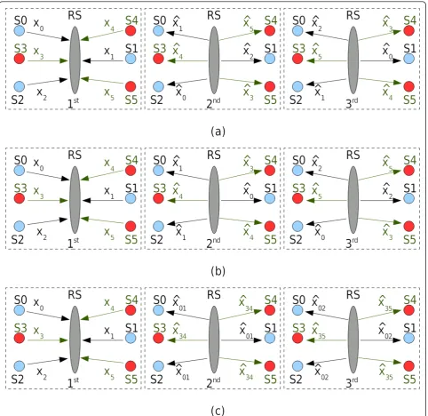
first phase, the MAC phase, all nodes transmit simulta-neously to the RS. In the followingP- 1 BC phases, the RS transmits to the nodes. Let p, p∈P, P ={2 , . . . ,P}, denote the index of the BC phase. In pth phase, in groupl, receiving noderl∈Ilis intended to receive the data stream of transmitting node tl∈Il\{rl}.
1) Unicasting Strategy
Using unicasting strategy, in each BC phase, the RS transmits different data streams to different nodes. Each data stream is intended only for one receiving node. Consequently, in each BC phase each node sees the other data streams transmitted by the RS to the other nodes as interference. The data stream transmitted from the RS to each particular node is changed in each BC phase, such that within P - 1 BC phases, each node receives the data streams from all other nodes in its group.
The relationship of the parameters p, rlandtlis given by
tl=al+ modNl(rl+p−al−1). (1)
Using such strategy, assuming each node knows its index and all other nodes’ indices in its group, there is no signalling required in the network. The proposed unicasting strategy is a generalization of the work in [3,10] forL = 1 andN1= 2, in [15] forL > 1 andNl= 2,∀l, and in [20] forL= 1 andN1 ≥2 with multiplexing
transmission. Figure 1a shows an example of the uni-casting strategy for MGMW relaying with L= 2 com-munication groups andN1=N2 = 3 nodes.
2) Hybrid Uni/Multicasting Strategy
For each served group, one data stream is transmitted to one node exclusively (unicast transmission) and one data stream is transmitted to the other Nl - 1 nodes (multicast transmission). In each BC phase, the uni-casted data stream is fixed and is transmitted to a differ-ent node in the group. Consequdiffer-ently, the multicasted data stream has to be changed in each BC phase to ensure that each node in each group receives all data streams of the other nodes in its group withinPphases. Compared to the unicasting strategy, intra-group inter-ference in each BC phase is reduced since only two data streams are transmitted simultaneously.
The procedure can be described as follows. For each groupl, the RS chooses one data stream out ofNl data streams. This data stream will be unicasted to different nodes in different BC phases. Therefore, in each BC phase, to ensure that each node receives theNl- 1 data streams from the other Nl- 1 nodes, the multicasted data stream is the transmitted data stream of the node who will receive the unicasted data stream. In the fol-lowing, we derive the mathematical formulation of the procedure for hybrid uni/multicasting.
In the lth group, given the indextlu ∈Ilof the
trans-mit node whose data stream is unicasted by the RS and the index tlm∈IlM, IlM=Il\{tlu}, of the transmit node
whose data stream is multicasted, the relationship betweenrl,tl, andpis defined by
tl=
tlu, ifrl=tlm
tlm, otherwise
(2)
where
tlm=
(p+al)−1, for (p+al)≥tlu+ 2
(p+al)−2, for (p+al)≤tlu+ 1
. (3)
The relationships in (2) and (3) are defined after choosing the data stream to be unicasted for groupl,tlu,
which remains the same in allNl - 1 BC phases. In the pth phase, node rl=tlm, whose data stream is
multi-casted by the RS, receives the unimulti-casted data stream fromtlu. The other nodes, rl, rl∈Il\{tlm}, receive the
RS to theseNl- 1 nodes. The multicasted data stream is changed in every BC phase as defined in Equation (3).
Using hybrid uni/multicasting strategy, the nodes need to know which data stream is unicasted and which data stream is multicasted by the RS in the pth phase. How-ever, given (2) and (3), and by choosing the unicasted data stream from the node with the lowest index, that is,tlu =al, there is no signalling effort needed. The RS is
then multicasting the data streams in the P - 1 BC phases starting from the lowest index in the set Il\{tlu=al}. In case of one-pair two-way relaying and
multi-user two-way relaying, the hybrid uni/multicasting strategy is the same as the unicasting strategy. The pro-posed hybrid uni/multicasting strategy is a generalisation of the work in [3,10] for L= 1 and N1 = 2, and in [15]
for L> 1 andNl= 2,∀l. Figure 1b shows an example of the proposed hybrid uni/multicasting strategy for MGMW relaying whenL= 2 andN1=N2= 3 nodes. 3) Multicasting Strategy
streams of nodes Svl,vl∈Il, and Swl,wl∈Il\{vl}, in the lth group, to allNlnodes in groupl. Prior to detection, each node has to cancel the self- and known-interfer-ence from each of the received data streams using the available side information. The side information can be its own transmitted data stream or a data stream which has been decoded in one of the previous BC phases. The general rule for selecting the two data streams for each group in each BC phase is that we have to ensure that the data stream of each node in each group is selected at least once.
The relationship betweenrl,tl, and pcan be written as
tl=
vl, forrl=wl,
wl, otherwise. (4)
Given the general rule, we may have several options to define the superposed data stream. However, each option will lead to different signaling requirement, since the RS has to inform the nodes about the indices vlandwlin each BC phase. In this work, we are interested in an option that does not need any signalling. Therefore, we extend the proposal in [20] to the case of MGMW relay-ing. We always choosevl=al, and, consequently,wlis changed in each BC phase and is selected successively based on the relationship defined bywl=vl+p- 1.
Using such relationships, node Srl =al always per-forms self-interference cancellation, i.e., xvlwl−xvl=al, to obtain all Nl - 1 data streams from other nodestl=wl,
∀wl∈Il\{al}. Regarding the other nodes rl∈Il\{al}, they have to be able to decode xaland, afterwards, use xalto perform known-interference cancellation. Each noderl∈Il\{al}has to wait until its own data stream is superposed with xvl=al, that is in thepth phase which leads to rl = (p + al) -1. In this corresponding pth phase, node rl = (p+al) - 1 performs self-interference cancellation, i.e.,xvlwl−xwl=(p+al)−1to obtainxvl=al. After-wards, usingxvl=al, it performs known-interference can-cellation xvlwl−xvl=alto obtain the other data stream from the other nodestl=wl,∀wl∈Il\{al,rl}received in the other BC phases. The proposed multicasting strategy is a generalisation of the work in [1,22,24] forL= 1 and N1 = 2, in [16] forL> 1 and Nl= 2, ∀l, and in [20] for L= 1 andN1≥2 with analog network coding
transmis-sion. Figure 1c shows an example of MGMW relaying using the multicasting strategy whenL= 2 andN1 =N2
= 3 nodes.
In this subsection, we have mathematically formulated the BC strategies. With the assumption of time-invariant channels within P phases, for unicasting strategy, any other relationship that one may derive will lead to the same performance. The relationships given in Section II-A1 has an advantage that it does not require any sig-naling in the network. For hybrid uni/multicasting, one
may also find other relationship than the relationships given in (2) and (3). However, with the time-invariant channels assumption and given the sametlu, the same
performance will be obtained. In Section II-A2, we choosetlu=alsuch that there will be no signaling in the
network. This is sub-optimum and one may improve the performance by exhaustively searching the besttlu,
∀l. This will lead to a higher computational complexity and also requires signalling in the network since the RS needs to inform all nodes in group labout the chosen tlu. Regarding multicasting strategy, in this work we
pro-pose vl=al andwl =p+al-1 which does not require any signaling in the network. This is sub-optimum and one may improve the performance by exhaustively searching vl and wl which optimises the performance while fulfilling the general rule for multicasting strategy as described in Section II-A3. However, the computa-tional complexity will be higher and there are signaling needed since the RS needs to inform the nodes in group laboutvlandwl.
Note that all the relationships of parameters which are described in this subsection can also be directly applied for the case when the numbers of nodes are not equal in all groups. If the numbers of nodes are not equal in all groups, in each pth phase, the RS serves only the groups withNl≥p.
B. Generalised System Model
In this subsection, we explain the generalised system model for non-regenerative MGMW relaying which is valid for all BC strategies. In order to have non-regen-erative MGMW relaying with a specific BC strategy, the relationship ofp, rl, andtl as described in the previous subsection has to be set accordingly.
The overall channel matrix from the nodes to the RS is given by H= [h0, ...,hN−1]∈CM×N, with
i∈I,i∈I, the channel vector between node Siand the RS. The channel coefficient hi, m,m∈M, M={1, . . ., M}, follows CN(0, σx2). The vector
x∈CN×1is equal to (x0,..., xN-1)T, with xi the transmit signal of node Sithat follows CN(0,σx2). The AWGN
noise vector at the RS is denoted as
zRS= (zRS1, ...,zRSM)T∈CM×1 with zRSm following CN(0, σz2RS). In this work, we assume that all nodes transmit with fixed and equal transmit power.
In the first phase, all nodes transmit simultaneously to the RS and the received signal at the RS is given by
yRS=Hx+zRS. (5)
denoted by matrixGp, to the received signals and trans-mits to the nodes. Therefore,Gphas to be designed to ensure that the MGMW relaying is performed according to the chosen BC strategy. It is assumed that there is a transmit power constraint at the RS. The received signal vector of all nodes in thepth phase can be written as
ypnodes=HTGp(Hx+zRS) +zpnodes, (6)
In this section, we derive the sum rate expression of non-regenerative MGMW relaying. We start by defining the signal to interference and noise ratio (SINR) for the BC strategies. The achievable sum rate of MGMW relaying for both asymmetric and symmetric traffic are explained afterwards. The achievable sum rate is the sum of the rates received at all nodes. Asymmetric traf-fic refers to the situation where we allow all nodes in the group to transmit with different rates. Each node transmits with a rate that ensures that in the following Nl - 1 consecutive BC phases, all Nl - 1 nodes in its group can decode its data stream correctly. Symmetric traffic is when all nodes in group l have to transmit simultaneously with the same rate that is defined by the lowest rate among all possible link combinations of receive and transmit node (rl,tl) in groupl.
A. Signal to Interference and Noise Ratio
It is assumed thatxi, ∀i,zRSm, ∀m, andzi,∀i, are all sta-tistically independent. Therefore, given the received sig-nal in (7), the SINR for the link between receiving node Srland transmitting node Stlis given by
with the useful signal power at node Srl
Srl = E{|h
the RS’s propagated noise power which appear at node Srl
The interference power at receiving node Srl, is given by
Irl=Isgrl+Iogrl, (12)
withIsg
rlthe same group interference power and Iogrl the other group interference power. While Isg
rldepends on the applied BC strategy,Iogrldoes not depend on the BC strategy and it is given by
Iogrl =
d∈Il
E{|hTrlGphdxd|2}=
d∈Il
|hTrlGphd|2σx2. (13)
At each receiving node Srl,Isgrlincludes the interfer-ence power caused by its own data stream and other data streams that have been decoded in the previous BC phases. These a priori known data streams can be can-celed by each receiving node prior to detection by per-forming self- and known-interference cancellation. If self- and known-interference cancellation is performed, the remaining interference power which is not canceled by the receiving node,Inot - cancrl, is given by
Inot - cancrl =Isgrl−Icancrl (14)
withIcancrlthe interference power caused by the data streams which are a priori known by the receiving node Srland is canceled. With interference cancellation, the interference power in (12) can be rewritten as
Irl=Inot - cancrl+Iogrl. (15)
In the following, we explain IsgrlandInot - cancrlfor each
BC strategy.
1) Unicasting
The same group interference power is given by
Iusg
cancellation,Inot - cancrlfor unicasting strategy is given by
with Brl the set of the nodes’ indices whose data streams have been decoded by receiving noderlin the previous BC phases.
2) Hybrid uni/multicasting
The same group interference power can be decoupled into two parts. The first part is the interference caused by the unicasted or the multicasted data stream, denoted byIu/mrl.
The second part is the interference caused by other data streams which can only appear at the receiving noderlif the transceive beamforming applied at the RS cannot fully suppress it. The same group interference power is given by
Iu/msgrl =Iu/mrl+
withtlu the index of the transmitting node whose data
stream is unicasted by the RS,tlmthe index of the
trans-mitting node whose data stream is multicasted by the RS, and
the interference at the nodes which only can be either from the unicasted data stream (atNl - 1 nodes which are intended to receive the multicasted data stream) or from the multicasted data stream (at the node which receives the unicasted data stream). Similar to the uni-casting strategy, interference cancellation at the nodes can also be applied. For hybrid uni/multicasting trans-mission,Inot - cancrlis defined by
Iu/mnot - cancrl=Iul+
withBlthe sets of nodes’indices whose data streams have been multicasted by the RS in the previous BC phases and
The same group interference power can be decoupled into two parts. The first part is the inherent interference within the superposed data stream which can only be either self- or known-interference, denoted by Is|k. The
second part is the interference caused by other data streams which can only appear at the receiving node rl if the transceive beamforming applied at the RS cannot fully suppress it. The same group interference power is given by whose data streams are superposed by the RS in thepth phase.
Is|krlis the self- or known-interference power, which
can only be either self-interference power at nodesrl= wlandrl=vlgiven by
with vwl˜ the index of the known-interference which can only be either wlor vl. As explained in Section II-A3, Is|krlcan be cancelled and, thus,Is|krl = 0. Moreover,
once the nodes have decoded other nodes’data streams from the previous BC phases, they may use them to reduce the amount of interference in the second sum-mand in (22). For the multicasting strategy,Inot - cancrlis
defined by
with Brl the set of the nodes’ indices whose data streams have been decoded by receiving noderlin the previous BC phases.
B. Sum Rate for Asymmetric Traffic
Given the SINR as in (8), the information rate at receiv-ing noderl when it receives from transmitting nodetlin thepth phase is given by
Rrl,tl = log2(1 +γ
p
Since in MGMW relaying there is only one MAC phase, the transmitting node tl has to ensure that its data stream can be decoded correctly by all Nl - 1 intended receiving nodes. Consequently, we have
Rtl = min rl∈Il\{tl}
(Rrl,tl), (27)
which is the minimum rate among all receiving nodes rlin group l when they receive the data stream from a certain transmitting nodetl. The achievable sum rate of non-regenerative MGMW relaying is given by
SRasym= 1
P L
l=1 ⎛
⎝(Nl−1)
tl∈Il Rtl
⎞
⎠. (28)
The factor Nl- 1 is since in group lthere are Nl - 1 nodes that receive the same data stream from a certain transmitting node tl. The scaling factor1P is due to P channel uses for MGMW relaying.
One important note regarding (27) is that by taking the minimum, we ensure each node Sitransmits xiwith the rate that can be decoded correctly by all other nodes in its group. Thus, knowingxi, all other nodes in the group can use it to perform known-interference can-cellation in a similar fashion to their self-interference cancellation.
C. Sum Rate for Symmetric Traffic
In certain scenarios, there may be a requirement to have a symmetric traffic between all nodes in group l. All nodes communicate with the same data rate defined by the minimum ofRtl,∀tl,tl∈Il. The achievable sum rate for symmetric traffic for all BC strategies is given by
SRsymm= 1
P L
l=1
(Nl−1)Nl
min
tl∈Il Rtl
. (29)
Transceive Beamforming
In this section, first, we formulate the optimisation pro-blem of finding the optimum transceive beamforming maximising the sum rate. Afterwards, we explain the design of generalised low complexity transceive beam-forming algorithms for all BC strategies. It is assumed that perfect channel state information is available at the RS whose number of antennas is higher than or equal to the total number of the nodes, i.e.,M≥N.
A. Sum Rate Maximisation
The optimisation problem of finding the optimum transceive beamforming maximising the sum rate of non-regenerative MGMW relaying for asymmetric traf-fic can be written as
max
Gp
i f(i,p)
Rf(i,p),i
s.t. tr{Gp(HR
xHH+RzRS)G
pH}=E RS,
(30)
withRx= E{||xxH||22}, RzRS = E{||zRSz
H
RS||22}, and f(i, p)
the receiving node index, which is a function of trans-mitting index iand BC phase index p, and depends on the applied BC strategy.
In this work, we assume that the transmit powers at the nodes are fixed and equal. In order to improve the sum rate, one could have the transmit powers at the nodes as variables to be optimised subject to a power constraint at each node. However, since there is only one MAC phase, one has to find the optimum transmit power at each node and, simulateneously, the transceive beamforming for all BC phases, i.e., Gp,∀p,p∈P. This joint optimisation problem would further increase the computational effort.
The optimisation problem in (30) is non-convex and it requires high computational complexity to find the glo-bal optimum solution. Thus, in the following, we pro-pose generalised low complexity transceive beamforming algorithms for all proposed BC strategies.
As mentioned in Section II-B and as seen in (30), the transceive beamformingGpdepends on the BC strategy applied at the RS. In order to design generalised trans-ceive beamforming for all BC strategies and to make the problem more tractable, we decouple Gpinto transmit beamforming GpT, BC-strategy-defining permutation matrix Πp and receive beamforming GpR, such that
Gp=GpTpGpR.
In the following, we explain specially designed trans-ceive beamforming for MGMW relaying. First, we explain the generalised linear transceive beamforming based on three different optimisation criteria, namely, MF, ZF, and MMSE. Afterwards, we explain the general-ised BC-strategy-aware (BCSA) transceive beamforming.
B. Linear Transceive Beamforming
In this subsection, we explain the design of three low complexity generalised linear transceive beamforming algorithms, namely, MF, ZF, and MMSE. Since we have only one MAC phase, the receive beamforming is com-puted only once, i.e.,GpR=GR,∀p∈P. The
are based on different motivations. In [9], the downlink (from the RS to the nodes) channel matrix is a per-muted matrix of the uplink (from the nodes to the RS) channel matrix. Therefore,Πpin [9] is a diagonal matrix with weighting factors in each of its diagonal elements. Such approach as in [9] is only suitable for unicasting strategy. Hence, our generalised transceive beamforming is a generalisation of the three-step transceive beam-forming for two-way relaying in [9].
1) Matched Filter
Given the received signal at RS as in (5), the output of the receive filtering is given by
ˆ
XRS=GRyRS=GR(Hx+zRS). (31)
The MF optimisation problem for receive beamform-ing can be written as
GRMF = arg max
The objective function in (32) can be written as
|E{xHxˆ
By taking the derivative of (33) with respect toGRand
setting it equal to zero, we have [see, e.g, [25,26]]
GRMF =RxH
HR−1
zRS. (34)
The received signal at the nodes in (6) can now be rewritten as
RSthe transmitted signals from the RS
in the pth phase. The MF optimization problem for transmit beamforming can be written as
GpTMF = argmax [26] by deriving the Lagrangian function and solving the Karush-Kuhn-Tucker (KKT) conditions, we have
GpTMF =βMFp H∗, (37) where βMFp ∈R+is needed to fulfill the power
con-straint and given by
βp
Given (31), the ZF optimisation problem for receive beamforming can be written as
GRZF= argmin function in (39) can be written as
E{||x− ˆxRS||22}= tr
Using the same steps as in [26] by deriving the Lagrangian function and solving the KKT conditions, we have [see, e.g., [25]]
Given (35), the ZF optimisation problem for transmit beamforming can be written as
GpTZF = argmin
Table 1 BC-strategy-defining permutation matrices ofL=
objective function in (42) can be written as
Using the same steps as in [26] by deriving the Lagrangian function and solving the KKT conditions, we have
GpTZF =βZFp H∗(HTH∗)−1, (44) where βZFp ∈R+is needed to fulfill the power con-straint and given by
βp
3) Minimisation of Mean Square Error
Given (31), the MMSE optimisation problem for receive beamforming can be written as
GRMMSE= argmin
GR
E{||x− ˆxRS||22}. (46)
The objective function in (46) can be written as
E{||x− ˆxRS||22}= tr
Rx−2R(GRHRx) +GRHRxHHGHR+GRRzRSGHR
. (47)
By taking the derivative of (47) with respect to GRand
setting it equal to zero, we have [see, e.g., [25,26]]
GRMMSE=RXH
HHR
XHH+RzRS
−1
. (48)
Given (35), the MMSE optimisation problem for transmit beamforming can be written as
{GpTMMSE, βMMSEp }= argminE
where 1/bpis introduced to modify the mean square error as in [27,28]. Using the same steps as in [28] by deriving the Lagrangian function and solving the KKT conditions, we have
straint and given by
βp
Finally, for MF, ZF, and MMSE the transceive beam-forming is given by
Gp=βa1gorithmp GpTalgorithmpGpRalgorithm, (52) where the subscript (·)algorithmrefers to either MF, ZF,
or MMSE.
C. Broadcast-Strategy-Aware Transceive Beamforming
In the following, we explain the design of BCSA trans-ceive beamforming. Based on the chosen BC strategy, the RS separates the data streams which are going to be transmitted in the BC phase and transmits to the corre-sponding node or nodes. For unicasting strategy, the RS separates all data streams and transmits each data stream to each corresponding receiving node. For hybrid uni/multicasting, for each group, the RS separates the unicasted data stream from the other data streams and transmits it to the corresponding node whose data stream is multicasted. The RS also separates the multi-casted data stream from the other data streams and transmits it to the remaining nodes in the correspond-ing group. For multicastcorrespond-ing strategy, the RS separates the superposition of two data streams from the others and transmits the superposed data stream to all nodes in the group.
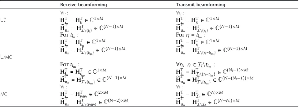
In order to compute the transceive beamforming, we first compute the equivalent channels for receive beam-forming and transmit beambeam-forming. The equivalent channels are needed to ensure that there will be no interstream interference received at the unintended receiving node or nodes. In order to find the equivalent channel, BD as proposed in [17] can be applied. Several works have considered BD for separation of data streams, e.g., [16,20,29,30]. In this work, we also con-sider regularised BD (RBD) as proposed in [23]. RBD avoids the drawbacks of BD which has a quite poor per-formance if the subspaces of the users channel matrices overlap significantly [23].
Equivalent channel
Without loss of generality, in the following we omit the BC phase index p. Let HiTn ∈Cηin×M and
˜
HTun ∈C(N−ηin)×M denote the channel matrix of the
intended nodes and the channel matrix of the other unintended nodes, respectively, withηin the number of
BC strategies, we have to setHTin andH˜Tunaccordingly. Table 2 shows the correspondingHT
inandH˜
T
unfor all BC
strategies. Given the singular value decomposition (SVD) of the unintended nodes’channels as
˜
we compute the equivalent channel for the intended nodesHeqi
n. The equivalent channel is given by
Heqin =HTinFnull, (54)
where Fnull is the null-space matrix which can be
computed either using BD or RBD. Using BD, Fnull=V˜ directly for receive and transmit beamforming, since it only deals with the channels without considering the noise. Using RBD, however, the equivalent channels for receive and transmit beamforming need to be computed differently. RBD for transmit beamforming has been derived in [23] and in this work, we provide the deriva-tion of RBD for receive beamforming in the appendix.
Using RBD, Fnull =V˜un
for transmit beamforming [23] andκ = σ 2 RS
σ2
x for receive beamforming, see appendix.
HavingHeqi
n, we can now compute the receive
beam-forming and transmit beambeam-forming. In the following,
when computing the receive beamforming,Heqin andηin
relate toHTin andH˜Tun as defined in Table 2 for receive beamforming, while when computing transmit beam-forming,Heqin andηinrelate toHTin andH˜
T
unas defined in
Table 2 for transmit beamforming.
In this work, we consider signal processing algo-rithms which do not deal with interference sinceHeqin is free from unwanted data streams, namely, MF, SVD, and semidefinite relaxation (SDR) of maximising the minimum SNR. MF and SVD for single-pair two-way relaying have been investigated in [3,10]. The BD-MF and BD-SDR have been designed in [20] for single-group multi-way relaying for multicasting strategy. BD-SVD has been designed in [16] only for multi-user two-way relaying with multicasting strategy. In this work, BCSA transceive beamforming is designed for non-regenerative MGMW relaying for all proposed BC strategies. Due to the requirement to make generalised BCSA transceive beamforming also suitable for non-regenerative MGMW relaying with multicasting strat-egy, it has a slight difference to [3,10,16]. Using BCSA for multicasting strategy, for each groupl, the RS has to transmit one data stream, which is a superposition of two data streams, to Nl nodes in the group where Nl can be any number higher than two. For that rea-son, in the design of receive beamforming using MF and SVD, we have to do a superposition of two data streams. This makes the proposed BCSA not a direct generalisation of [3,10,16]. However, for cases of one-pair two-way relaying and multi-user two-way relaying, if the superposition is not performed, BCSA is a gener-alisation of [3,10,16].
Table 2 The correspondingHTinandH˜T
unfor all BC strategies
Receive beamforming Transmit beamforming
∀tl: ∀rl:
UC, unicasting; U/MC, hybrid uni/multicasting; MC, multicasting tlu: index of transmitting node whose data stream is unicasted,tlu ∈Il
Matched filter The receive beamforming vector is
poses (adds) two-data streams from two nodes in each group for multicasting strategy. in = mean(|H
T inm˜
T|)
can be seen as receive power loading where the modulus operator | · | is assumed to be applied element-wise and the mean function returns the mean of a vector.
The transmit beamforming vector is given by
mDL=FnullHeqHin 1ηin
multicasting strategy,1ηinreplicates the superposed data
streamηintimes.
Singular value decomposition Let the SVD of the equivalent channel be given by
Heqin =Ueqineqin[Veq(1)in ,Veq(0)in ], (57) The receive beamforming vector is given by
m=in1
T|)the receive power loading.
The transmit beamforming vector is given by
mDL=FnullV
Since in MGMW relaying all member nodes in each group exchange messages, we are also interested in a fair beamforming algorithm which aims at balancing the SNRs at the RS as well as at the receiving nodes in each group.
The SNR balancing problem for receive beamforming can be written as
msdr= arg max
with Iin the set of intended nodes with cardinality
equal toηin.iin is the index of a member node inIinand
heqi
in ∈H
eq
in. The receive beamforming is given by
m=inm
sdr|)the receive power loading.
Equation (60) is a non-convex quadratically con-strained quadratic program. A similar optimisation is also considered in [31]. It is proved to be NP-hard in [31]. Nonetheless, it can be approximately solved using SDR techniques [31,32]. We will not go further into this relaxation and the interested reader may find more detailed derivation in [20,31,32].
The SNR balancing problem for transmit beamform-ing can be written as
msdr DL= arg max
in. The transmit beamforming is given by
mDL=FNu11msdr DL
loading. Note that to compute the transmit beamform-ing with SDR, we assume that the information of the noise power at the nodes is available at the RS. Similar to (60), (62) can be approximately solved with semidefi-nite relaxation techniques using a solver such as SEDUMI [33].
In the following, we use again the BC phase indexpto describe the BCSA transceive beamforming. For unicast-ing strategy, the receive beamformunicast-ing matrix is given by
GpR = [mp1,. . ., mpN], (64)
wheremptl, ∀tl∈I, is the receive beamforming as in (55), (58) or (61) given the equivalent channel of node tl. The transmit beamforming matrix is given by
GpT=mpDL1,. . ., mpDL1, (65) wherempDL
rl, ∀rl∈I, is the transmit beamforming as in (56), (59), or (63) given the equivalent channel of node rl.
GpR =mpt1u,mpt1m, . . ., mptLu, mptLm, (66) where mmptlu, ∀l∈L, andm
p
tlm, ∀l∈Lare the receive
beamforming as in (55), (58), or (61) given the equiva-lent channels of nodestluandtlm, respectively. The
trans-mit beamforming matrix is given by
GpT= !
mpDLr 1=t1m,m
p
DLI1\{t1m},. . .,m p
DLrL=tLm,m p DLIL\{tLm}
" , (67)
where mpDL
rl=tlm, ∀l∈L, andm
p
DLIl\{tlm}, ∀l∈L, are the
transmit beamforming as in (56), (59), or (63) given the equivalent channel of node rl=tlmand the equivalent
channel of all other nodes in group l, ∀rl∈Il\{tlm},
respectively.
For multicasting strategy, the receive beamforming matrix is given by
GpR = [mpl,. . ., mpL], (68)
where mpl, ∀l∈L, is the receive beamforming as in (55), (58), or (61) given the equivalent channels of two nodesvland wlwhose data streams are superposed. The transmit beamforming matrix is given by
GpT=mpDL1,. . ., mpDLL, (69) wherempDLl,∀l∈L, is the transmit beamforming as in (56), (59), or (63) given the equivalent channels of all nodes in groupl.
Finally, BCSA transceive beamforming is given by
Gp=βpGp
TpG
p
R. (70)
where bp is needed in order to satisfy the transmit power constraint at the RS, with
βp=
ERS
tr#GpTpGp
R(σx2HHH+σRS2I)G
pH
R p
H
GpTH$ .(71)
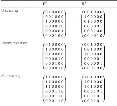
Note thatΠpis not the same for all BC strategies. For unicasting strategy, Πp is the same as for MF, ZF, and MMSE, where an example for L = 2, N1 = N1 = 3 is
given in Table 1. For hybrid uni/multicasting strategy, Πp
=I2Land for multicasting strategy,Πp=IL.
Simulation Results
In this section, the sum rate performance is analysed based on simulation results. We set σz2RS =σz2node= 1, σ2
x = 1, andERS= 1. The channel coefficients are i.i.d.
CN(0, σx2), i.e., Rayleigh fading. Hence, the SNR value is given by σ
2
x
σ2
znode|
hi,m|2= σ
2
x
σ2
zRS|
hi,m|2.
We consider three scenarios. The first two scenarios are the well-known scenarios, namely, one-pair two-way relaying and multi-user two-way relaying. We consider both scenarios to show that the proposed BC strategies and the generalised transceive beamforming designed in this work are valid for both well-known scenarios. The third scenario is the two-group multi-way case, where each group consists of three nodes.
A. First Scenario: L = 1 and N1= 2
In one-pair two-way relaying, unicasting and hybrid uni/ multicasting are the same. Figure 2 shows the sum rate performance of one-pair two-way relaying with MF, ZF, and MMSE transceive beamforming for both ametric traffic and symametric traffic. Regarding sym-metric traffic, to reduce the number of lines in the figure, we only plot the result for MF transceive beam-forming. The approximation of maximum sum rate is also provided for two cases, i.e., with optimised and with fixed transmit power at the nodes. Both optimum transceive beamforming solutions maximising the sum rate were computed using fmincon from MATLAB to provide performance bounds for two-way relaying. We use the value of MMSE transceive beamforming as the initial value. In general, using MF, ZF and MMSE trans-ceive beamforming, unicasting and hybrid uni/multicast-ing outperform multicastuni/multicast-ing strategy. A direct superposition of the output of receive beamforming for the multicasting strategy doubles the amount of the RS’s filtered noise. Moreover, the RS transmit power is dis-tributed within the superposed data stream and after the self-interference cancellation, each node only receives half of the power. Since each node performs self-inter-ference cancellation, no interself-inter-ference appears at the nodes, and thus, for all BC strategies MF outperforms MMSE and ZF. At low SNR, MMSE converges to MF and in high SNR, ZF converges to MMSE. In this work, we assume fixed transmit power at all nodes and the performance of unicasting and hybrid uni/multicasting with MF is close to the approximation of maximum sum rate with fixed transmit power. If the nodes can optimise their transmit power, the sum rate is improved with a penalty of having higher computational complex-ity. It can also be seen that asymmetric traffic leads to a higher rate compared to symmetric traffic since the rate for symmetric traffic is defined by the weakest link among all available links. Therefore, in the following, we only consider asymmetric traffic.
0 5 10 15 20 25 30 0
1 2 3 4 5 6 7 8 9 10
SNR in dB
Average Sum Rate (b/s/Hz)
Approx. Max Sum Rate with optimised transmit power Approx. Max Sum Rate with fixed transmit power UC=U/MC: MF asymmetric
UC=U/MC: MF symmetric MC: MF asymmetric MC: MF symmetric UC=U/MC: MMSE asymmetric MC: MMSE asymmetric UC=U/MC: ZF asymmetric MC: MF asymmetric
Figure 2Sum rate performance of first scenario with MF, ZF, and MMSE; UC, unicasting; U/MC, hybrid uni/multicasting; MC, multicasting.
0 5 10 15 20 25 30
0 1 2 3 4 5 6 7 8 9 10
SNR in dB
Average Sum Rate (b/s/Hz)
Approx. Max Sum Rate with optimised transmit power
Approx. Max Sum Rate with fixed transmit power
MC: RBD−SDR=BD−SDR
MC: RBD−MF=BD−MF
UC=U/MC: RBD−MF=RBD−SVD=RBD−SDR
MC: RBD−SVD=BD−SVD
UC=U/MC: BD−MF=BD−SVD=BD−SDR
hybrid uni/multicasting strategies, BD-MF, BD-SVD, and BD-SDR perform the same and they have similar perfor-mance to multicasting strategy with SVD. Different to multicasting strategy, for unicasting and hybrid uni/mul-ticasting, since there is a stream separation both in receive beamforming and transmit beamforming, RBD improves the performance in low SNR region. In high SNR region, BD converges to RBD. For unicasting and hybrid uni/multicasting strategies, since the equivalent channels (which are free from interference) always cor-respond only to one intended node for both receive beamforming and transmit beamforming, MF, SVD, and SDR will always have the same performance. It can be seen that multicasting strategy with SDR performs best. Hence, having a suitable transceive beamforming, one can exploit the benefit of beamforming-based physical layer network coding for non-regenerative single group multi-way relaying as proposed in [20].
B. Second Scenario: L = 2 and N1= N2= 2
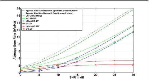
Figure 4 shows the sum rate performance of multi-user two-way relaying with MF, ZF, and MMSE transmit beamforming. In this scenario, unicasting and hybrid uni/multicasting are the same and they outperform mul-ticasting strategy. The reason is the same as in the case of one-pair two-way relaying. Moreover, the direct superposition of the output of receive beamforming for
multicasting strategy not only increases the amount of the RS’s filtered noise but also increases the unwanted interference at the receiving nodes. For all strategies, MMSE performs best and in high SNR region, ZF verges to MMSE, while in low SNR region, MF con-verges to MMSE. Different to the case of one-pair two-way relaying, in multi-user two-two-way relaying MF per-forms worse since it does not cancel the interference from other pairs which appears at each node. The trans-ceive beamforming maximising the sum rate was com-puted using fmincon from MATLAB to provide a bound for multi-user two-way relaying. We use the value of MMSE tranceive beamforming as initial value. It can be clearly seen that if the transmit power at the nodes can be optimised, the sum rate can be improved at the expense of computational complexity.
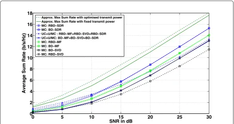
Figure 5 shows the sum rate performance of multi-user two-way relaying with BCSA transceive beamform-ing. In general, RBD outperforms BD in low SNR region and BD converge to RBD in high SNR. Only for multi-casting strategy, BD-SVD outperforms RBD-SVD for all SNR values and it has similar performance as unicasting and hybrid uni/multicasting with BD-MF, BD-SVD, and BD-SDR. The gain of RBD compared to BD is obtained most for unicasting and hybrid uni/multicasting strate-gies, while for multicasting strategy (with MF and SDR), the gain is small. In medium to high SNR region,
0 5 10 15 20 25 30
0 2 4 6 8 10 12 14 16 18
SNR in dB
Average Sum Rate (b/s/Hz)
Approx. Max Sum Rate with optimised transmit power Approx. Max Sum Rate with fixed transmit power UC=U/MC: MMSE
MC: MMSE UC=U/MC: ZF MC:ZF UC=U/MC: MF MC: ZF
multicasting strategy with RBD-SDR or BD-SDR per-forms best. While for both unicasting and hybrid uni/ multicasting strategies, the performance of MF, SVD, and SDR is the same, for multicasting strategy SDR always performs best followed by MF and SVD.
C. Third Scenario: L = 2 and N1= N2= 3
Figure 6 shows the sum rate performance of two-group three-way relaying using MF, ZF, and MMSE. In general hybrid uni/multicasting performs best followed by uni-casting and multiuni-casting strategies. While hybrid uni/
0 5 10 15 20 25 30
0 2 4 6 8 10 12 14 16 18
SNR in dB
Average Sum Rate (b/s/Hz)
Approx. Max Sum Rate with optimised transmit power Approx. Max Sum Rate with fixed transmit power MC: RBD−SDR
MC: BD−SDR
UC=U/MC : RBD−MF=RBD−SVD=RBD−SDR UC=U/MC: BD−MF=BD−SVD=BD−SDR MC: RBD−MF
MC: BD−MF MC: BD−SVD MC: RBD−SVD
Figure 5Sum rate performance of second scenario with BCSA; UC, unicasting; U/MC, hybrid uni/multicasting; MC, multicasting.
0 5 10 15 20 25 30
0 5 10 15 20 25 30
SNR in dB
Average Sum Rate (b/s/Hz)
U/MC: MMSE UC: MMSE MC: MMSE U/MC: ZF UC: ZF MC: ZF U/MC: MF UC: MF MC: MF
multicasting strategy with MMSE slightly ouperforms unicasting strategy with MMSE, both strategies have similar ZF performance. With MMSE, we find the trade off between the noise enhancement and the interference suppression. Since, hybrid uni/multicasting has smaller number of transmit data streams from the RS, it per-forms better than unicasting strategy both for MMSE and MF. ZF perfectly cancels the interference, and, thus, both unicasting and hybrid uni/multicasting perform similar. In general, for all strategies, ZF converges to MMSE in high SNR region and in low SNR region, MF converges to MMSE. It can be seen that multicasting strategy is outperformed by other strategies since it suf-fers from the increase of RS’s filtered noise and the reduced received power at the nodes. This shows that analog network coding for non-regenerative MGMW relaying obtained by directly adding the output of receive beamforming (using MF, ZF, and MMSE receive beamforming) is not an efficient strategy and, thus, appropriate transceive beamforming is required.
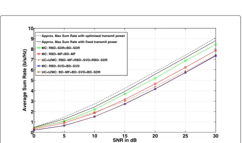
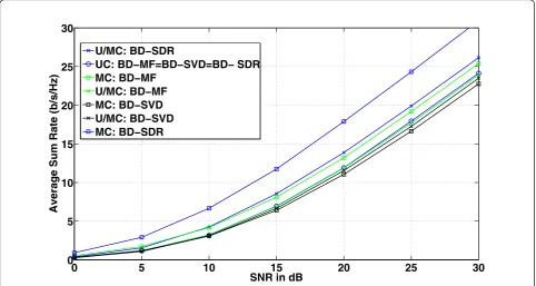
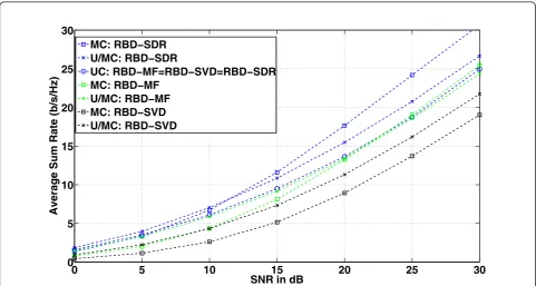
Figs. 7 and 8 show the sum rate performance of two-group three-way relaying using BCSA transceive beam-forming with BD and RBD, respectively. Comparing both the figures, in general, RBD outperforms BD, and they converge in high SNR. Only when using SVD, for both hybrid uni/multicasting and multicasting strategies, RBD-SVD performs worse than BD-SVD and BD-SVD does not converge to RBD-SVD in high SNR region. In
medium to high SNR, multicasting strategy outperforms other strategies when using SDR and MF. However, if SVD is applied, unicasting strategy performs best. For unicasting strategy, MF, SVD and SDR have similar performance.
Comparing Figures 6, 7, and 8, one can clearly see that BCSA transceive beamforming improves the sum rate performance compared to MF, ZF, and MMSE transceive beamforming, especially for multicasting strategy. For the multicasting strategy, only RBD-SVD performs worse than ZF and MMSE. For the hybrid uni/multicasting strategy, BD-MF performs similar to ZF, RMF performs similar to MMSE and both BD-SDR and RBD-BD-SDR outperform MF, ZF, and MMSE. For the unicasting strategy, MF, SVD, and BD-SDR perform similar to ZF, while RBD-MF, RBD-SVD, and RBD-SDR perform similar to MMSE. The highest sum rate (especially in high SNR) is obtained by multi-casting strategy with BCSA BD-SDR and RBD-SDR. Therefore, provided a suitable transceive beamforming is used which can exploit analog network coding, the sum rate of non-regenerative MGMW relaying can be improved.
Conclusion
In this paper, we consider non-regenerative MGMW relaying. A multi-antenna RS assists L communication groups, whereNl nodes in each group communicate to
0 5 10 15 20 25 30
0 5 10 15 20 25 30
SNR in dB
Average Sum Rate (b/s/Hz)
U/MC: BD−SDR
UC: BD−MF=BD−SVD=BD− SDR MC: BD−MF
U/MC: BD−MF MC: BD−SVD U/MC: BD−SVD MC: BD−SDR
each other but not with other nodes in other groups. The number P of communication phases is equal to maxl Nl. Three BC strategies are proposed, namely, unicasting, hybrid uni/multicasting, and multicasting. We derive the sum rate expression for non-regenera-tive MGMW relaying for asymmetric and symmetric traffic. We address the optimum transceive beamform-ing maximisbeamform-ing the sum rate of non-regenerative MGMW relaying. We design generalised low complex-ity sub-optimum transceive beamforming for all BC strategies, namely, MF, ZF, MMSE, and BCSA trans-ceive beamforming. It is shown that the performance of non-regenerative MGMW relaying depends on the BC strategy and the applied transceive beamforming. While multicasting strategy using BCSA SDR provides better sum rate performance compared to other strate-gies, however, if either MF, ZF, or MMSE are applied, multicasting strategy is outperformed by the other strategies.
Appendix
RBD for Receive Beamforming
For receive beamforming, the RS has to ensure that the interference from other users to the intended userican be minimised while taking into consideration the appearance of noise at the RS. The matrix FNull is
designed to achieve the aim and, by rewriting the opti-misation problem for transmit beamforming in [23]
Equation (9) we have the optimisation problem for receive beamforming,
FNu11i,∀i= arg min
Fi,∀i
E % N
i=1
||FiH˜iun||
2+||FizRS||2
β−1 &
,
s.t.βE{ ||xixHi ||}=Pnodes,
(72)
where bis a scaling factor needed to fulfill the nodes’ transmit power constraint. In this work, we assume that all nodes transmit with fixed and equal unit power and, thus, the constraint can be written as
β= Pnodes E{||xixHi ||}=
1
σ2
x
. (73)
The objective function in (72),f(Fi), can be written as
f(Fi) = N
i=1
trFiHiunH
H
iunF
H
i
+σ 2 RSIM
σ2
x
trFHi Fi
.(74)
Let the SVD ofHiunbe given by
Hiun =Uiun i˜unViun, (75)
(74) can be rewritten as
f(Fi) = N
i=1
tr
FiUiun
˜iun˜T iun+
σ2 RSIM σ2
x
UHiunF
H i
. (76)
0 5 10 15 20 25 30
0 5 10 15 20 25 30
SNR in dB
Average Sum Rate (b/s/Hz)
MC: RBD−SDR U/MC: RBD−SDR
UC: RBD−MF=RBD−SVD=RBD−SDR MC: RBD−MF
U/MC: RBD−MF MC: RBD−SVD U/MC: RBD−SVD
Let Fi =FaiFbi and let Fbi=U
H
iun, the optimisation
problem reduces to
whereFai needs to be positive definite in order to find a nontrivial solution [23]. Using the results from [23,34], we have
The work of Aditya U. T. Amah is supported by the‘Excellence Initiative’of the German Federal and State Governments and the Graduate School of Computational Engineering, Technische Universität Darmstadt. The authors would like to thank the anonymous reviewers whose review comments are very helpful in improving this article.
Some parts of this paper have been presented at the IEEE ICASSP 2010, Dallas, USA, and IEEE WCNC 2010, Sydney, Australia.
Author details
1Graduate School of Computational Engineering and Communications
Engineering Lab, Technische Universität Darmstadt, Darmstadt 64283 Germany2Communications Engineering Lab, Technische Universität
Darmstadt, Darmstadt 64283 Germany
Competing interests
The authors declare that they have no competing interests. Received: 23 December 2010 Accepted: 5 July 2011 Published: 5 July 2011
References
1. B Rankov, A Wittneben, Spectral efficient protocols for half-duplex relay channels. IEEE Journal on Selected Areas in Communications,25(2), 379–389 (Feb. 2007)
2. T Oechtering, Spectrally Efficient Bidirectional Decode-and-Forward Relaying for Wireless Networks. Ph.D dissertation, TU Berlin (2007)
3. T Unger, Multi-antenna two-hop relaying for bi-directional transmission in wireless communication systems. Ph.D dissertation, TU Darmstadt (2009) 4. E Biglieri, R Calderbank, A Constantinides, A Goldsmith, HV Poor,MIMO
Wireless Communication(Cambridge University Press, 2007)
5. D Tse, P Viswanath,Fundamentals of Wireless Communication(Cambridge University Press, 2005)
6. I Hammerström, M Kuhn, C Esli, J Zhao, A Wittneben, G Bauch, MIMO two-way relaying with transmit CSI at the relay. inProc IEEE Signal Processing Advances in Wireless Communications, Helsinki, 1–5 (June 2007) 7. TJ Oechtering, RF Wyrembelski, H Boche, Multiantenna bidirectional
broadcast channels - optimal transmit strategies. IEEE Transactions on Signal Processing,57(5), 1948–1958 (May 2009)
8. TJ Oechtering, EA Jorswieck, RF Wyrembelski, H Boche, On the optimal transmit strategy for the mimo bidirectional broadcast channel. IEEE Transactions on Communications,57(12), 3817–3826 (2009)
9. T Unger, A Klein, Duplex schemes in multiple-antenna two-hop relaying. EURASIP Journal on Advances in Signal Processing2008. Article ID 128592 (2008)
10. Y-C Liang, R Zhang, Optimal analogue relaying with multiantennas for physical layer network coding, inProc IEEE International Conference on Communications, Beijing. 3893–3897 (2008)
11. R Zhang, Y-C Liang, CC Chai, S. Cui, Optimal beamforming for two-way multi-antenna relay channel with analogue network coding. IEEE Journal on Selected Areas in Communications,27(5), 699–712 (June 2009)
12. M Chen, A Yener, Multiuser two-way relaying for interference limited systems. inProc IEEE International Conference on Communications, Beijing, 3883–3887 (2008)
13. C Esli, A Wittneben, One- and two-way decode-and-forward relaying for wireless multiuser mimo networks. inProc IEEE Global Communications Conference, New Orleans, 1–6 (2008)
14. AUT Amah, A Klein, YCB. Silva, A Fernekeß, Multi-group multicast beamforming for multiuser two-way relaying. inProc International ITG Workshop on Smart Antennas, Berlin. (2009)
15. J Joung, AH Sayed, Multiuser two-way amplify-and-forward relay processing and power control methods for beamforming systems. IEEE Transactions on Signal Processing,58(3), 1833–1846 (March 2010)
16. E Yilmaz, R Zakhour, D Gesbert, R Knopp, Multi-pair two-way relay channel with multiple antenna relay station. inProc IEEE International Conference on Communications, Cape Town, (May 2010)
17. QH Spencer, AL Swindlehurst, M Haardt, Zero-forcing methods for downlink spatial multiplexing in multiuser MIMO channels. IEEE Transaction on Signal Processing,52, 461–471 (Feb 2004). doi:10.1109/TSP.2003.821107 18. D Gündüz, A Yener, A Goldsmith, HV Poor, Multi-way relay channel. Proc
IEEE International Symposium on Information Theory, Seoul. (2009) 19. S Simoens, Cooperative MIMO Communications, Information Theoretical
Limits and Practical Coding Strategies. Ph.D dissertation, TU Catalonia (UPC) (2009)
20. AUT Amah, A Klein, Beamforming-based physical layer network coding for non-regenerative multi-way relaying. EURASIP Journal on Wireless Communications and Networking, Special Issue on Physical Layer Network Coding for Wireless Cooperative Networks2010. Article ID 521571 2010. 21. A transceive strategy for regenerative multi-antenna multi-way relaying,
Proc. IEEE International Workshop on Computational Advances in Multi-Sensor Adaptive Processing, Aruba. (Dec. 2009)
22. S Katti, S Gollakota, D Katabi, Embracing wireless interference: analog network coding. Proc ACM Special Interest Group on Data Communication, Kyoto, 397–408 (2007)
23. V Stankovic, M Haardt, Generalized design of multi-user mimo precoding matrices. IEEE Transactions on Wireless Communications,7, 953–961 (2008) 24. P Popovski, H Yomo, Wireless network coding by amplify and forward for
bi-directional traffic flows. IEEE Communications Letters,11(1), 16–18 (2007) 25. JA Nossek, M Joham, W Utschick, Transmit processing in mimo wireless
systems. Proc IEEE International Symposium on Emerging Technologies, Shanghai (May 2004)
26. M Joham, Optimization of linear and non-linear transmit signal processing. Ph.D dissertation, TU München (2004)
27. M Joham, K Kusume, MhH Gzara, W Utschick, JA Nossek, Transmit wiener filter for downlink of tddds-cdma systems. Proc IEEE International Symposium on Spread-Spectrum Techniques and Applications (May 2002) 28. M Joham, W Utschick, JA Nossek, Linear transmit processing in mimo
communications systems. IEEE Transactions on Signal Processing,53(8), 2700–2712 (Aug. 2005)
29. YCB Silva, Adaptive beamforming and power allocation in multi-carrier multicast wireless network. Ph.D dissertation, TU Darmstadt (2008) 30. YCB Silva, A Klein, Linear transmit beamforming techniques for the
multi-group multicast scenario. IEEE Transactions on Vehicular Technology,58, 4353–4367 (Oct. 2009)
31. ND Sidiropoulos, TN Davidson, ZQ Luo, Transmit beamforming for physical-layer multicasting. IEEE Transaction on Signal Processing.54, 2239–2251 (2006)
32. E Karipidis, ND Sidiropoulos, ZQ Luo, Quality of service and max-min fair transmit beamforming to multiple cochannel multicast groups. IEEE Transaction on Signal Processing.56(3), 1268–1279 (2008) 33. JF Sturm, Using sedumi 1.02, a matlab toolbox for optimisation over
symmetric cones. Optimisation Methods and Software.11-12, 625–653 (June 1999)
34. A Scaglione, P Stoica, S Barbarosa, G Giannakis, H Sampath, Optimal designs for space-time linear precoders and decoders. IEEE Transactions on Signal Processing,50(5), 1051–1064 (May 2002). doi:10.1109/78.995062 doi:10.1186/1687-1499-2011-29