ABSTRACT
CHEN, GUOYANG. Optimizing Data Placement and Threads Management for Heterogeneous Computing. (Under the direction of Xipeng Shen.)
© Copyright 2016 by Guoyang Chen
Optimizing Data Placement and Threads Management for Heterogeneous Computing
by Guoyang Chen
A dissertation submitted to the Graduate Faculty of North Carolina State University
in partial fulfillment of the requirements for the Degree of
Doctor of Philosophy
Computer Science
Raleigh, North Carolina
2016
APPROVED BY:
Vincent Freeh Frank Mueller
Huiyang Zhou Xipeng Shen
DEDICATION
BIOGRAPHY
Guoyang Chen was born in Leping, Jiangxi, China. He received his Bachelor’s degree in Computer Science from University of Science and Technology of China in 2012. After graduation, Chen was admitted to the Computer Science Department at The College of William and Mary as a Ph.D. student in the Fall of 2012. In 2013, Chen started to work with his advisor, Dr.Xipeng Shen. In the Fall of 2014, to continue working with Dr.Xipeng Shen, Chen transferred to NC State University as a Ph.D. student in the Computer Science Department.
ACKNOWLEDGEMENTS
Foremost, I would like to thank my advisor, Dr.Xipeng Shen for his help, support, patience, and encouragement throughout my Ph.D. studies. His technical and editorial advice was essential to the completion of this dissertation. I am grateful to his many helps on my research and other aspects of life. I could not have imagined having a better advisor.
Besides my advisor, I would like to thank the rest of my dissertation committees: Dr.Vincent Freeh, Dr. Frank Mueller and Dr.Huiyang Zhou for their time and efforts to schedule my final defense exam, their insightful comments and helpful research suggestions during my whole Ph.D. studies. I would also like to thank Skip Booth and John Marshall for offering me the internship oppor-tunities in their group and their helps on complementing the practical usages of the techniques proposed in my dissertation.
My sincere thanks also goes to Dr.Huiyang Zhou and Dr.Lars Nyland for their reviews and guidance on my researches. I especially thank Dr.Huiyang Zhou for his guidance and efforts on publishing the paper in the ASAP conference and job recommendations for me to AMD.
I will not forget to extend my gratitude to Dr.George N. Rouskas, Ms.Kathy Luca and all others in the graduate school at NC state for their helps with my Ph.D. study, transferring credits, reviewing my graduate plan of work and approving my graduation.
I also thank all lecturers, friends, personnel, and colleagues at NC state and College of William and Mary.
Thanks are also due to all the wonderful people who’ve helped me.
TABLE OF CONTENTS
LIST OF TABLES . . . ix
LIST OF FIGURES. . . x
Chapter 1 Introduction. . . 1
1.1 Memory Efficiency . . . 2
1.2 Thread Management . . . 2
1.3 Overview of the Dissertation . . . 3
Chapter 2 Background . . . 5
2.1 GPU Memory Hierarchy . . . 5
2.2 GPU Thread Management . . . 6
Chapter 3 PORPLE . . . 9
3.1 Problem Statement . . . 9
3.2 Overview of Proposed Solution . . . 12
3.3 MSL: Memory Specification for Extensibility . . . 13
3.3.1 MSL . . . 13
3.3.2 Example . . . 15
3.3.3 GUI and Other Facilities . . . 17
3.4 Placer: Performance Modeling and Placement Search . . . 17
3.4.1 Lightweight Performance Modeling . . . 17
3.4.2 Search for the Best . . . 20
3.5 PORPLE-C: Staging for Runtime Placement . . . 21
3.6 Other Details . . . 24
3.7 Evaluation . . . 25
3.7.1 Methodology . . . 25
3.7.2 Results with Regular Benchmarks . . . 27
3.7.3 Results with Irregular Benchmarks . . . 28
3.8 Related Work . . . 33
Chapter 4 Multiview . . . 35
4.1 Problem Statement . . . 35
4.2 Overview of Proposed Solution . . . 38
4.3 Coherence-Free Multiview . . . 39
4.3.1 Definition and Connections with Data Placement . . . 39
4.3.2 Coherence-Free Theorem . . . 41
4.4 Enabling Reference-Discerning Placement . . . 44
4.4.1 Background on PORPLE . . . 44
4.4.2 Compiler Support . . . 45
4.4.3 Runtime Support . . . 46
4.5 Evaluation . . . 48
4.5.2 Performance Results . . . 49
4.6 Related Work . . . 56
Chapter 5 Free Launch . . . 57
5.1 Problem Statement . . . 57
5.2 Overview of Proposed Solution . . . 58
5.3 Launch Removal Transformation . . . 59
5.3.1 A Running Example . . . 60
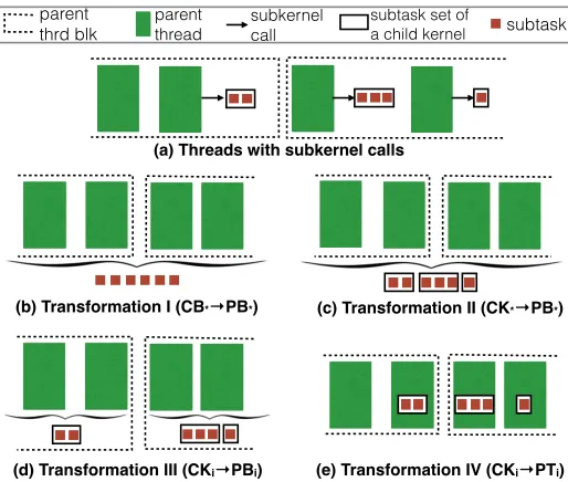
5.3.2 Four Types of Subtask Assignments . . . 60
5.3.3 Transformation forC B∗→P B∗ . . . 62
5.3.4 Transformation forC K∗→P B∗ . . . 66
5.3.5 Transformation forC Ki→P Bi . . . 66
5.3.6 Transformation forC Ki→P Ti . . . 67
5.3.7 Other Complexity . . . 67
5.4 Task Assignment Selection . . . 68
5.5 Implementation . . . 69
5.6 Evaluation . . . 73
5.6.1 Methodology . . . 73
5.6.2 Overall Performance . . . 74
5.6.3 Analysis through Hardware Counters . . . 79
5.6.4 Sensitivity to Different Inputs . . . 80
5.7 Related Work . . . 81
Chapter 6 Effisha . . . 83
6.1 Problem Statement . . . 83
6.2 Overview of Proposed Solution . . . 85
6.3 Terminology and Granularity . . . 86
6.4 Overview of EffiSha . . . 88
6.5 Preemption-Enabling Code Transformation . . . 89
6.5.1 Low-Overhead Kernel Preemption . . . 91
6.6 EffiSha API and Runtime: Basic Design . . . 91
6.6.1 GPU-Stubs and State Transitions . . . 92
6.6.2 Basic Implementation of the Runtime . . . 93
6.7 Enhanced Design and Optimized Implementation . . . 94
6.7.1 Enhancing Applicability . . . 94
6.7.2 Improving Efficiency . . . 96
6.7.3 Setting Priority . . . 97
6.7.4 Memory Size and Dynamic Parallelism . . . 98
6.8 Scheduling Policies . . . 98
6.9 Evaluation . . . 99
6.9.1 Methodology . . . 99
6.9.2 Support of Preemptions and Priorities . . . 100
6.9.3 Eviction Delay . . . 101
6.9.4 Benefits from Preemptive Scheduling . . . 102
6.10 Discussion . . . 107
6.11 Related Work . . . 108
Chapter 7 Sweet-KNN . . . .110
7.1 Problem Statement . . . 110
7.2 Overview of Proposed Solution . . . 112
7.3 Background . . . 112
7.3.1 GPU . . . 113
7.3.2 Triangle Inequality (TI) and Landmarks . . . 113
7.3.3 TI-Based KNN . . . 114
7.4 Basic Implementation of TI-Based KNN on GPU . . . 117
7.4.1 Step 1: Initialize Clusters . . . 117
7.4.2 Step 2: Choose Candidate Clusters (level-1 filtering) . . . 118
7.4.3 Step 3: Point-level filtering (level-2 filtering) . . . 118
7.5 Sweet KNN . . . 119
7.5.1 Overview . . . 121
7.5.2 Enabling Algorithmic Elasticity . . . 122
7.5.3 Implementation-Level Optimizations . . . 123
7.5.4 Adaptive Scheme . . . 126
7.6 Evaluations . . . 129
7.6.1 Methodology . . . 129
7.6.2 Overall Performance . . . 130
7.6.3 Sensitivity Study . . . 132
Chapter 8 Erasure Coding. . . .136
8.1 Problem Statement . . . 137
8.2 Overview of Proposed Solution . . . 137
8.3 COMPUTATIONAL COMPLEXITY OF RS CODING . . . 138
8.4 Reed-Solomon Coding on CPUs . . . 140
8.5 Reed-Solomon Coding on GPUs . . . 141
8.5.1 Vectorization to Optimize GPU Memory Bandwidth . . . 141
8.5.2 Exploration of Different Implementations for GF(28) Multiplications . . . 142
8.5.3 Overcoming Memory Bandwidth Limit Using Texture Caches, Tiling, and Prefetching . . . 142
8.5.4 Hiding Data Transmission Latency Over PCIe . . . 143
8.5.5 Shared Virual Memory to Eliminate Memory Copying . . . 143
8.6 Reed-Solomon Coding on FPGAs . . . 143
8.6.1 Vectorization to Optimize FPGA Memory Bandwidth . . . 144
8.6.2 Exploration of Different Implementations for GF(28) Multiplications . . . 144
8.6.3 Overcoming Memory Bandwidth Limit Using Tiling and Prefetching . . . 144
8.6.4 Kernel Replication to Fully Utilize FPGA Logic Resource . . . 145
8.7 Experiment Methodology . . . 145
8.8 Experimental Results . . . 146
8.8.1 Performance Optimizations for CPUs . . . 146
8.8.3 Performance Optimizations for FPGAs . . . 150
8.8.4 Performance Comparison amongst Different Accelerator Architectures . . . 152
8.9 Related Work . . . 153
Chapter 9 Conclusions and Future Works . . . .155
9.1 Conclusions . . . 155
9.2 Future Works . . . 157
LIST OF TABLES
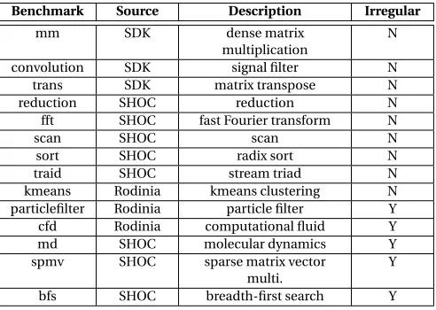
Table 3.1 Benchmark Description. . . 26
Table 3.2 Machine Description. . . 26
Table 3.3 Memory latency description. cL1 and cL2 are L1 and L2 caches for constant memory. gL1 and gL2 are L1 and L2 caches for global memory. tL1 and tL2 are L1 and L2 caches for texture memory. . . 27
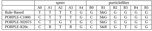
Table 3.4 Placement decisions made by PORPLE and the rule-based approach. T: texture memory, C: constant memory, G: global memory, S: shared memory, R:read-only data cache. Spmv: A0:rowDelimiters, A1:cols, A2:vec, A3:val, A4:out. Parti-clefilter: B0:CDF, B1:u, B2: arrayX, B3:arrayY, B4:xj,B5:yj. . . 31
Table 4.1 Machine Description. . . 48
Table 4.2 Data Placement Strategy for BFS on K20c. . . 51
Table 4.3 Bandwidth Usage for Gaussian_fan2 . . . 52
Table 4.4 Placement decisions made by the rule-based approach, PORPLE and Multiview. 52 Table 4.5 Speedups of Cross Runs. . . 54
Table 5.1 Machine Description. . . 74
Table 5.2 Benchmarks . . . 74
Table 5.3 Speedups of CCL and BT over the original SKL version. . . 74
Table 5.4 Details of each kernel. . . 76
Table 6.1 Benchmarks . . . 100
Table 6.2 Kernel lengths and priorities. . . 100
Table 7.1 An example of warp divergence for KNN without opt . . . 124
Table 7.2 An example of warp divergence for KNN with map . . . 124
Table 7.3 Datasets From UCI . . . 129
Table 7.4 Performance details of KNN-TI and Sweet KNN. . . 131
LIST OF FIGURES
Figure 2.1 CUDA programming model . . . 7
Figure 3.1 High-level structure of PORPLE. . . 13
Figure 3.2 Syntax of MSL with some token rules omitted. . . 15
Figure 3.3 MSL expressions for the serialization conditions of various memory. . . 16
Figure 3.4 The memory specification of Tesla M2075 in MSL. . . 16
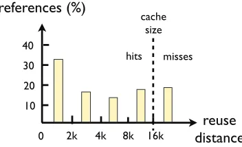
Figure 3.5 Illustration of a reuse distance histogram and its relation with cache miss rate estimation. . . 18
Figure 3.6 Codelets in CUDA for accessing an element in an arrayA. . . 21
Figure 3.7 Generated placement-agnostic code. . . 24
Figure 3.8 Speedup of regular benchmarks on Tesla K20c. . . 28
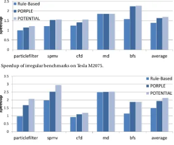
Figure 3.9 Speedup of irregular benchmarks on Tesla K20c. . . 29
Figure 3.10 Speedup of irregular benchmarks on Tesla M2075. . . 30
Figure 3.11 Speedup of irregular benchmarks on Tesla C1060. . . 30
Figure 3.12 The breakdown of overhead for irregular benchmarks on Tesla K20c. . . 31
Figure 3.13 Speedup across different inputs for particlefilter. . . 32
Figure 3.14 Speedup across different inputs for spmv. . . 32
Figure 4.1 Placement Example:A codelet of a GPU kernel with multiple references to a single data object. . . 36
Figure 4.2 Pseudo-code for finding out the breath-first search (BFS) order (to store in arraylevels) of each node in a graph. . . 37
Figure 4.3 Pseudo-code of SSSP, which computes the length of the shorest path from a nodesrcto all other nodes in a graph. . . 44
Figure 4.4 Speedup of Benchmarks on Tesla K20c. . . 49
Figure 4.5 Speedup of Benchmarks on Tesla M2075. . . 50
Figure 4.6 Runtime overhead on irregular benchmarks on Tesla K20c. . . 50
Figure 4.7 Speedup of Gaussian_fan1 on Different Inputs. . . 55
Figure 4.8 Speedup of Gaussian_fan2 on Different Inputs. . . 55
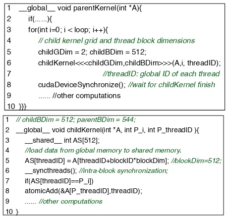
Figure 5.1 DynCall: An example codelet representing GPU kernels with dynamic paral-lelism. . . 60
Figure 5.2 Illustration of the four assignments (b,c,d,e) of subtasks enabled by thelaunch removalprogram transformations on a kernel with subkernel calls (a). . . 61
Figure 5.3 Transformation result forC B∗→P B∗. The black code is what the transforma-tion inserts; other code is from the original program. . . 64
Figure 5.4 The main part of theC K∗→P B∗transformation that differs from theC B∗→ P B∗. . . 66
Figure 5.5 The main part of theC Ki→P Bi transformation that differs from theC B∗→ P B∗. Theworklistbecomes a variable local to a parent thread block. . . 66
Figure 5.6 Transformation result forC Ki→P Ti. . . 67
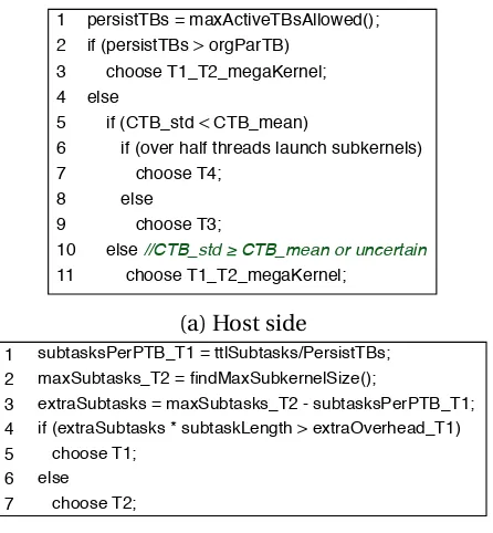
Figure 5.8 An example of subtasks assignments by T1 (in broken lined bars) and T2 (in
solid lined bars). . . 70
Figure 5.9 High level structure offree launch. . . 70
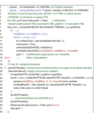
Figure 5.10 A codelet for code generations. threadID, blockID and gridDim are changed to one dimension value. . . 71
Figure 5.11 A sample of runtime version selection put in the host-side code before a kernel call. . . 72
Figure 5.12 Speedups over the version that uses subkernel launches. The “original” bars show the performance of the original version of the code without using sub-kernel launches (CCLandBTalready uses subkernel launches in their original version, hence excluded from that category). Table 5.3 shows the detailed results ofCCLandBT. . . 75
Figure 5.13 SM efficiency. . . 79
Figure 5.14 Achieved SM occupancy. . . 80
Figure 5.15 Speedup of BFS across different inputs . . . 81
Figure 6.1 A kernel for matrix addition. . . 86
Figure 6.2 Four levels of GPU scheduling granularity. . . 87
Figure 6.3 The maximum length of a task in SHOC benchmarks (the largest input in the benchmark suite are used). . . 88
Figure 6.4 Overview of EffiSha. . . 88
Figure 6.5 Illustration of the effects ofpreemption-enablingcode transformation. Graphs (a) and (b) show the code of a GPU program before and after the transforma-tion; graph (c) uses matrix addition as an example to show the changes to the body of the kernel: from the default thread-block ID indexed form to a block-task ID indexed form. . . 90
Figure 6.6 GPU-stubs and the possible state transitions of a GPU kernel. . . 92
Figure 6.7 Changes of the KState of a kernel in each stage of the execution of a GPU program (bold font shows the code inserted by the EffiSha compiler). . . 93
Figure 6.8 Implementation of the customized API for a synchronization on stream s. . . . 96
Figure 6.9 Total Number of Evictions for Different Priorities . . . 101
Figure 6.10 Eviction delay of each kernel. . . 102
Figure 6.11 Normalized turnaround time; SJF priorities are used. The benchmarks are put in an increasing order of their priorities (from left to right). . . 103
Figure 6.12 Average normalized turnaround time (ANTT) and overall system throughput (STP) under three priority settings. . . 104
Figure 6.13 Transformation overhead. . . 106
Figure 6.14 PKM overhead. . . 107
Figure 6.15 Scheduling overhead. . . 107
Figure 7.1 Two main directions for speeding up KNN. . . 112
Figure 7.2 Illustration of distance bounds obtained from Triangular Inequality through onelandmarkL. . . 114
Figure 7.4 Pseudo-code of the basic TI-based KNN. . . 115
Figure 7.5 Memory layouts fork N e a r e s t s(locations on one row are consecutive on memory). . . 121
Figure 7.6 Memory layouts of data points. . . 126
Figure 7.7 Adaptive scheme used in Sweet KNN (th1 and th2 are two thresholds described in Section 7.5.3.2.) . . . 127
Figure 7.8 Overall speedups over the CUBLAS-based basic KNN on GPU. . . 130
Figure 7.9 Speedups of Sweet KNN on differentk values (arcenehas only 100 points and hence does not have results atk=512). . . 133
Figure 7.10 Speedups by Sweet KNN on different # of landmarks (i.e. clusters). . . 134
Figure 7.11 Speedups by Sweet KNN on different # of threads for one query point. . . 135
Figure 8.1 Block-based Parity Encoding . . . 139
Figure 8.2 Coarse-grain partition for multi-threaded implementation on CPUs . . . 140
Figure 8.3 The CPU encoding bandwidth for different numbers of threads on a multi-core Xeon server . . . 146
Figure 8.4 The performance impact of GPU code optimizations. . . 147
Figure 8.5 Analysis of GPU pipeline stalls . . . 148
Figure 8.6 Multi-streaming(8 streams) to hide CPU-GPU data transmission latency through the PCIe bus.(light blue color: kernel execution; dark brown: data transmission latency). . . 149
Figure 8.7 Performance comparison between SVM and multi-streaming on APUs. . . 149
Figure 8.8 Performance impact of OpenCL code optimizations for FPGAs. . . 151
CHAPTER
1
INTRODUCTION
The development of modern processors exhibits two trends: massive parallelism and heterogeneity. With massive parallelism, hundreds or thousands of threads may run concurrently on a single processor, providing tremendous computing power. On the other hand, some specialized computing units are designed to dramatically accelerate certain types of tasks, offering some complement to traditional CPUs.
Graphic Processing Unit (GPU) is a kind of processors embodying both trends. A modern GPU contains thousands of cores that are usually smaller and simpler than a conventional CPU. But as these cores can run concurrently, they offer a much higher throughput than a conventional CPU does. GPU was initially designed for graphics rendering[Ren]. But in the last decade, it has been widely adopted for accelerating a large range of computing tasks, ranging from physics simulations to data analytics, linear algebra, financial analysis, computational biology, and so on.
1.1. MEMORY EFFICIENCY CHAPTER 1. INTRODUCTION
1.1
Memory Efficiency
To meet the ever growing demands of multi-/many-core processors for data accesses, modern memory systems manifest increasing varieties and complexities. On an NVIDIA Kepler GPU, for instance, there are more than eight types of memory (global, texture, shared, constant, various cache, etc.), with some on-chip, some off-chip, some directly manageable by software, and some not. The trend is stressed by the emergence of many memory technologies (e.g., stacked memory and non-volatile memory) recently.
Where to place the data of a program in a complex memory system is essential for capitalizing the sophisticated memory designs for performance[Jan11]. But it is often difficult for programmers to tell what data placements fit a program, because the answer depends on a deep understanding of the properties of the memory systems, and may differ when the program runs on different inputs or different machines.
Prior solutions to data placement have fallen into two categories: offline auto-tuning, and rule-based approach. The first tries many different placements and measures the performance on some training runs[ZM12]. This approach is time-consuming, and cannot easily adapt to the changes in program inputs or memory systems. The second approach uses some high-level rules derived empirically from many executions[Jan11]. These high-level rules are easy to use, but often fail to produce suitable placements, and their effectiveness degrades further when GPU memory systems evolve across generations.
1.2
Thread Management
To ensure fairness and efficiency on GPU, threads need to be managed in a harmonious way. Gen-erally, the best management strategy for different situations are different. For example, to achieve the best performance, threads should be scheduled to GPU in a balanced manner. However, to achieve the best locality, threads, which will access the same data, should be grouped together. As a result, it may lead to an imbalanced threads scheduling. Currently, threads on GPU are managed and scheduled by the hardware, which makes it less flexible to manage for users. In this dissertation, we mainly focus on two directions of thread management to enable dynamic parallelism and thread scheduling, as these two directions cause lots of overhead, unfairness and poor responsiveness. Dynamic parallelism refers to the case that the amount of parallelism is dynamic. By using software techniques, we complement the default hardware-based thread management and achieve some significant benefits.
1.3. OVERVIEW OF THE DISSERTATION CHAPTER 1. INTRODUCTION
feature allows a GPU kernel to launch a child kernel at runtime through some programming inter-face. However, the overhead is large due to many subkernel launches. In a recent work, Wang and Yalamanchili have characterized and analyzed subkernel launches in unstructured GPU applica-tions[WY14]and have proposed a new method called “Dynamic Thread Block Launch”[Wan15], which is a lightweight execution mechanism to reduce the high launching overhead. The work shows good potential in improving the efficiency, but requires extra hardware extensions. Yang and others develop a compiler called “CUDA-NP”[YZ14], which tries to exploit nested parallelism by creating a large number of GPU threads initially and use control flows to activate different numbers of threads for different code sections. The parallelism is limited to the number of threads in a thread block and has shown to work on nested loops only.
Many recent efforts have been reported to make GPUs first-class resource for system manage-ment. Gdev [Kat12]integrates the GPU runtime support into the OS. It allows GPU memory to be shared among multiple GPU contexts and virtualizes the GPU into multiple logic ones. GPUfs[Sil14] enables GPUs with the file I/O support. It allows the GPU code to access file systems directly through high-level APIs. GPUvm [Suz14]investigates full- and para-virtualization for GPU virtualization. Wang et al. [Wan14]proposed OS-level management for GPU memory rather than letting it man-aged by applications. All previous work are not satisfactory due to their lack of efficient preemption support.
1.3
Overview of the Dissertation
In this dissertation, I will introduce four different approaches to improving the performance of heterogeneous computing from the above two directions. Two of them are to address the above data placement problem and the other two are for better and more flexible thread management.
1.3. OVERVIEW OF THE DISSERTATION CHAPTER 1. INTRODUCTION
certain conditions, the multiple views can remain incoherent while facilitating enhanced data placement. We present a theorem and some compiler support to ensure the soundness of the usage of coherence-free multiview.
For thread management, I will first introducefree launch, a new software approach to overcoming the shortcomings of hardware-based dynamic parallelism in Chapter 5. It allows programmers to use subkernel launches to express dynamic parallelism. It employs a novel compiler-based code transformation namedsubkernel launch removalto replace the subkernel launches with the reuse of parent threads. To enable efficient preemptive scheduling of GPU kernels without special hardware support, EffiSha, a pure software framework that enables preemptive scheduling of GPU kernels with very low overhead, will be presented in Chapter 6. The enabled preemptive scheduler offers flexible support of kernels of different priorities, and demonstrates significant potential for reducing the average turnaround time and improving the system overall throughput of programs that time share a modern GPU.
CHAPTER
2
BACKGROUND
In this Chapter, I’ll first provide some background on GPU, its memory systems and default thread management. Our discussion will be based on the NVIDIA CUDA terminology[Cud](but the tech-nique can be applied to other GPUs with complex memory systems).
As a massively parallel architecture, GPU features hundreds or thousands of cores and a complex memory system. When a GPU kernel gets launched, usually thousands of threads will be created and many of them start running on GPU concurrently. These threads are organized in a hierarchy: 32 threads form a warp and they execute in lockstep, a number of warps form a thread block, and all blocks form a grid.
2.1
GPU Memory Hierarchy
To meet the large demands for data, a modern GPU typically consists of a number of types of memory. The memory system frequently changes across GPU generations. We take Tesla K20c (compute capability 3.5) as an example to explain the different properties of some types of GPU memory.
On Tesla K20c, there are four major types of software-manageable memory and five major types of cache:
2.2. GPU THREAD MANAGEMENT CHAPTER 2. BACKGROUND
accesses to it by a warp are more efficiently supported. Accesses to global memory go through a L2 cache. If the data are read-only, the accesses also go through a read-only cache, which sits above L2 cache and has a lower latency.
• Texture memory: It physically occupies the same piece of memory as global memory does, but offers a different view such that accesses to a data on texture memory go through L2 cache and a texture cache at the higher level (i.e., closer to the cores). A prominent feature of texture memory is its special support for 2-D or 3-D data locality. Texture memory is typically used for read-only data. Data on texture memory could be modified throughsurface writes, a special runtime API. However, the new value may not be visible to threads that access the data through texture memory API (because texture cache is not coherent with the memory).
• Constant memory: It is 64KB offline memory. It is for ready-only data. A special property is its broadcasting effect: When all threads in a warp access the same data element, the requests can be satisfied efficiently. But otherwise, the accesses get serialized. Accesses to constant memory go through L2 cache and constant cache.
• Shared memory: It is on-chip memory, much faster to access than other types of memory. The size can be configured as 16KB, 32KB and 48KB. It consists of 32 banks, allowing both read and write accesses. It is however subject to bank conflicts: When multiple threads access the same bank at the same time, the requests get serialized.
• Various cache: There are numerous types of hardware cache. They are not directly managed by software, but affect the performance on the off-chip memory substantially. All accesses to off-chip memory go through L2 cache; The size of L2 cache is 1536KB. Above L2, there are L1 cache, read-only cache, texture cache, and constant cache. Their latencies differ, but are all much shorter than the latency to L2 and off-chip memory. L1 cache on Tesla K20c is mainly for register spilling. Read-only cache shares the same physical cache with texture cache, used for accesses to read-only data on the global memory. Texture cache is for accesses to the texture memory. Constant cache is for accesses to the constant memory.
2.2
GPU Thread Management
2.2. GPU THREAD MANAGEMENT CHAPTER 2. BACKGROUND
main(){ …
copy<<<10000, 256>>>(a,b); …
}
__global__ void copy(int *a, int *b){
int tid = threadIdx.x + blockIdx.x*blockDim.x; b[tid]=a[tid];
}
a SIMD group (warp)
Graphic Processing Unit (GPU)
threads
(a) A simple GPU codelet
(b) CUDA programming model SM SM
Figure 2.1CUDA programming model
will be scheduled by hardware to all the SMs and they are organized into warps, which execute instructions in a lockstep as the SIMD(Single Instruction Multiple Data) fashion. The size of a warp is 32, fixed in NVIDIA GPUs. A number of warps compose a thread block. Threads in a thread block can communicate with each other by shared memory or barriers. Many thread blocks form a grid. In the example 2.1(a), host thread creates a grid with 10000 thread blocks. Each thread block contains 256 threads(8 warps). All threads will execute the copy kernel function. Inside the code, each thread will be have an unique tid, which is thread ID in the grid. They execute same copy instruction, but with different data.
Warps are scheduled by warp schedulers in each SM. Executions of different warps are switched by hardware with little overhead. When a warp send out a load request to hardware, due to the memory access latency, the hardware will schedule another warp to execute instead of waiting for the data loaded from memory. As a result, it can hide memory latency.
To enable more flexible thread management, recent GPUs support dynamic parallelism, which means threads on GPU can launch subkernels. The new created threads will be scheduled by hardware. There are mainly two options by current GPU, synchronous and asynchronous subkernel launch. The former will stall parent threads until subkernel finishes. The latter one will indicate that hardware schedule warps from parent kernel and subkernel in a same priority. Communication between parent kernel and subkernel can only go through global memory.
2.2. GPU THREAD MANAGEMENT CHAPTER 2. BACKGROUND
CHAPTER
3
PORPLE: AN EXTENSIBLE OPTIMIZER
FOR PORTABLE DATA PLACEMENT ON
GPU
In this Chapter, I will introduce our first technique named PORPLE to improve memory efficiency of heterogeneous computing.
3.1
Problem Statement
Modern Graphic Processing Units (GPU) rely on some complex memory systems to achieve high throughput. On an NVIDIA Kepler device, for instance, there are more than eight types of memory (including caches), with some on-chip, some off-chip, some directly manageable by software, and
0A version[Che14]of this Chapter has been published in "The Proceedings of the 47th Annual IEEE ACM International
Symposium on Microarchitecture", doi>10.1109/MICRO.2014.20
©2014 IEEE/ACM. Reprinted, with permission, from Guoyang Chen, Bo Wu, Dong Li, Xipeng Shen, "PORPLE: An Ex-tensible Optimizer for Portable Data Placement on GPU", 2014 47th Annual IEEE/ACM International Symposium on Microarchitecture, December/2014.
3.1. PROBLEM STATEMENT CHAPTER 3. PORPLE
some not. They each have their own sizes, properties, and access constraints. Studies have shown that finding the suitable kinds of memory to place data—called thedata placement problem—is essential for GPU program performance[Jan11]. But due to the complexity of memory and its continuous evolvement, it is often difficult for programmers to tell what data placements fit a program. For some programs, the suitable placements differ across the program inputs, making the placement even more difficult to do.
There have been some efforts to addressing the problem. Some of them use offline autotuning, which tries many different placements and measures the performance on some training runs[ZM12]. This approach is time-consuming, and cannot easily adapt to the changes in program inputs or memory systems. Some others use some high-level rules derived empirically from many executions on a GPU[Jan11]. These rules are straightforward, but as this chapter shows later, they often fail to produce suitable placements, and their effectiveness degrades further when GPU memory systems evolve across generations of GPU.
In this chapter, we introduce a new approach to address the data placement problem. We design the approach based on three principles.
First, the solution must have a good extensibility. GPU architecture changes rapidly, and every generation manifests some substantial changes in the memory system design. For a solution to have its lasting values, it must be easy to extend to cover a new memory system. Our solution features MSL (memory specification language), a carefully designed small specification language. MSL provides a simple, uniform way to specify a type of memory and its relations with other pieces of memory in a system. GPU memory has various special properties: Accesses toglobal memorycould get coalesced, accesses totexture memorycould come with a 2-D locality, accesses toshared memorycould suffer from bank conflicts, accesses toconstant memorycould get broadcast, and so on. A challenge is how to allow simple but yet well-structured descriptions of these various properties such that they can be easily exploited by a data placement mechanism. Our solution is based on the following insight: All of those special properties are essentially about the conditions, under which, concurrent access requests are serialized. We introduce a “serialization condition” field in the design of MSL, which allows the specification of all those special properties in logical expressions of a simple format. The design offers an underlying vehicle for data placement mechanisms to treat various types of memory in a single, systematic way. With this design, extending the language coverage to include a new memory system can be achieved by simply adding a new entry into the MSL specification. This design, along with the compiler support explained next, allows code to be easily ported into a new GPU architecture with data placement automatically optimized (Section 3.3).
3.1. PROBLEM STATEMENT CHAPTER 3. PORPLE
program inputs are not known until runtime, the data placement optimizer should be able to work on the fly, which entails two requirements. The first is to employ a highly efficient data placement engine with minimized runtime overhead. In our solution, we use an agile detection of data access patterns explained next, a lightweight memory performance model for fast assessing a data placement plan, and an open design that allows easy adoption of fast algorithms for searching for the best placement on the fly (Section 3.4). The second requirement is the ability to transform the original program such that it can work with an arbitrary data placement decided by the data placement engine at runtime. A typical GPU program does not meet the requirement because of its hardcoded data access statements that are valid only under a particular data placement. In our solution, we develop a source-to-source compiler named PORPLE-C, which transforms a GPU program into a placement-agnostic form. The form is equipped with some guarding statements such that executions of the program can automatically select the appropriate version of code to access data according to the current data placement. A complexity with this solution is a tension between the size of the generated code and the overhead of the guarding statements, which is addressed in our solution by a combination of coarse-grained and fine-grained versioning (Section 3.5).
Third, the solution should have a good generality. Data placement is important for both regular and irregular GPU programs (our results show an even higher potential on irregular programs, detailed in Section 3.7.) A good solution to the data placement problem hence should be applicable to both kinds of programs. Here the main challenge is to find out the data access patterns of irregular programs, as they are typically not amenable for compiler analysis. Our solution is to employ a hybrid method. In particular, the PORPLE-C compiler tries to figure out data access patterns through static code analysis. When the analysis fails, it derives a function from the GPU kernel with its memory access patterns captured. The function contains some recording instructions to characterize memory access patterns. At runtime, the function runs on CPU, but only for a short period of time. This hybrid method avoids runtime overhead when possible and at the same time makes the solution broadly applicable. (Section 3.6)
3.2. OVERVIEW OF PROPOSED SOLUTION CHAPTER 3. PORPLE
significantly.
Overall, the work in this chapter makes the following contributions:
• It presents the first general framework that supports cross-input, cross-architecture extensible optimizations of data placement for GPU.
• It introduces a simple yet flexible specification language that facilitates systematic description of various GPU memory systems.
• It proposes a way to produce placement-agnostic GPU programs through offline code staging and online adaptation.
• It describes a lightweight performance model for swift assessment of data placements and demonstrates its effectiveness for selecting suitable data placements for GPU programs.
• Through a comparison with manual and rule-based approaches, it empirically validates the significant benefits of PORPLE.
3.2
Overview of Proposed Solution
PORPLE enables cross-input, cross-architecture adaptive data placement through a combination of offline analysis and online adaptation.
As shown in Figure 3.1, at a high level, PORPLE contains three key components: a specification language MSL for providing memory specifications, a compiler PORPLE-C for revealing the data access patterns of the program and staging the code for runtime adaptation, and an online data placement enginePlacerthat consumes the specifications and access patterns to find the best data placements at runtime. These components are designed to equip PORPLE with a good extensibility, applicability, and runtime efficiency. Together they make it possible for PORPLE to cover a variety of memory, handle both regular and irregular programs, and optimize data placement on memory on the fly.
3.3. MSL: MEMORY SPECIFICATION FOR EXTENSIBILITY CHAPTER 3. PORPLE
PLACER (placing engine) MSL
(mem. spec. lang.)
PORPLE-C (compiler)
architect/user mem spec
org. program
access patterns
staged program
online profile
desired placement
efficient execution
offline online
microkernels
Figure 3.1High-level structure of PORPLE.
3.3
MSL: Memory Specification for Extensibility
An important feature of PORPLE is its capability to be easily extended to cover new memory systems. We achieve this feature by MSL. In this section, we first present the design of MSL, and then describe a high-level interface to enable easy creation of MSL specifications.
3.3.1 MSL
MSL is a small language designed to provide an interface for compilers to understand a memory system.
Figure 3.2 shows its keywords, operators, and syntax written in Backusâ ˘A¸SNaur Form (BNF). An MSL specification contains one entry for processor and a list of entries for memory. We call each entry a spec in our discussion. The processor entry shows the composition of a die, a TPC (thread processing cluster), and an SM.
3.3. MSL: MEMORY SPECIFICATION FOR EXTENSIBILITY CHAPTER 3. PORPLE
read and write operations, the spec allows the use of a tuple to indicate both. We use “upperLevels” and “lowerLevels” to indicate memory hierarchy; they contain the names or IDs of the memories that sit above (i.e., closer to computing units) or blow the memory of interest. The “shareScope” field indicates in what scope the memory is shared. For instance, “sm” means that a piece of the memory is shared by all cores on a streaming multiprocessor. The “concurrencyFactor” is a field that indicates parallel transactions a memory (e.g., global memory and texture memory) may support for a GPU kernel. Its inverse is the average number of memory transactions that are serviced concurrently for a GPU kernel. As shown in previous studies[HK09], such a factor depends on not only memory organization and architecture, but also kernel characterization. MSL broadly characterizes GPU kernels into compute-intensive and memory-intensive, and allows the “concurrencyFactor” field to be a tuple containing two elements, respectively corresponding to the values for memory-intensive and compute-intensive kernels. We provide more explanation of “concurrencyFactor” through an example later in this section, and explain how it is used in the next section.
GPU memories often have some special properties. For instance, shared memory has an impor-tant feature called bank conflict: When two accesses to the same bank of shared memory happen, they have to be served serially. But on the other hand, for global memory, two accesses by the same warp could be coalesced into one memory transaction if their target memory addresses belong to the same segment. While for texture memory, accesses can benefit from 2-D locality. Constant memory has a much stricter requirement: The accesses must be to the same address, otherwise, they have to be fetched one after one.
How to allow a simple expression of all these various properties is a challenge for the design of MSL. We address it based on an insight that all these special constraints are essentially about the conditions for multiple concurrent accesses to a memory to get serialized. Accordingly, MSL introduces a field “serialCondition” that allows the usage of simple logical expressions to express all those special properties. Figure 3.3 shows example expressions for some types of GPU mem-ory. Such an expression must start with a keyword indicating whether the condition is about two accesses by threads in a warp or a thread block or a grid, which is followed with a relational expres-sion on the two addresses. It also uses some keywords to represent data accessed by two threads:
3.3. MSL: MEMORY SPECIFICATION FOR EXTENSIBILITY CHAPTER 3. PORPLE
Keywords:
address1, address2, index1, index 2, banks, blockSize, warp, block, grid, sm, core, tpc, die, clk, ns, ms, sec, na, om, ?;
// na: not applicable; om: omitted; ?: unknown; // om and ? can be used in all fields
Operators:
C-like arithmetic and relational operators, and a scope operator {};
Syntax:
•
specList ::= processorSpec memSpec*•
processorSpec ::= die=Integer tpc; tpc=Integer sm; sm=Integer core; end-of-line•
memSpec ::= name id swmng rw dim size blockSize banks latency upperLevels lowerLevels shareScope concurrencyFactor serialCondition ; end-of-line•
name ::= String•
id ::= Integer•
swmng ::= Y | N // software manageable or not•
rw ::= R|W|RW // allow read or write accesses•
dim ::= na | Integer // special for arrays of a particular dimensionality•
sz ::= Integer[K|M|G|T| ][E|B] // E for data elements•
size ::= sz | <sz sz> | <sz sz sz>•
blockSize ::= sz | <sz sz> | <sz sz sz>•
lat ::= Integer[clk|ns|ms|sec] // clk for clocks•
latency ::= lat | <lat lat>•
upperLevels ::= <[id | name]*>•
lowerLevels ::= <id*>•
shareScope ::= core | sm | tpc | die•
concurrencyFactor ::= < Number Number>•
serialCondition ::= scope{RelationalExpr}•
scope ::= warp | block | gridFigure 3.2Syntax of MSL with some token rules omitted.
memory); they however get serialized otherwise. This simple way of expression makes it possible for other components of PORPLE to easily leverage the features of the various memory to find good data placements, which will be discussed in the next section.
3.3.2 Example
3.3. MSL: MEMORY SPECIFICATION FOR EXTENSIBILITY CHAPTER 3. PORPLE
Examples of serialization conditions: constant mem:
warp{address1 != address2} shared mem:
block{word1!=word2 && word1%banks == word2%banks} global mem:
warp{ address1/blockSize != address2/blockSize }
Figure 3.3MSL expressions for the serialization conditions of various memory. Mem spec of Tesla M2075:
die =1 tpc; tpc = 16 sm; sm = 32 core;
globalMem 8 Y rw na 5375M 128B ? 600clk <L2 L1> <> die <0.1 0.5> warp{ address1/blockSize != address2/blockSize }; L1 9 N rw na 16K 128B ? 80clk <> <L2 globalMem> sm ? warp{ address1/blockSize != address2/blockSize };
L2 7 N rw na 768K 32B ? 390clk om om die ? warp{ address1/blockSize != address2/blockSize };
constantMem 1 Y r na 64K ? ? 360clk <cL2 cL1> <> die ? warp{address1 != address2};
cL1 3 N r na 4K 64B ? 48clk <> <cL2 constantMem> sm ? warp{ address1/blockSize != address2/blockSize }; cL2 2 N r na 32K 256B ? 140clk <cL1> <cL2 constantMem> die ? warp{ address1/blockSize != address2/blockSize };
sharedMem 4 Y rw na 48K ? 32 48clk <> <> sm ? block{word1!=word2 && word1%banks ==word2%banks};
… …
Figure 3.4The memory specification of Tesla M2075 in MSL.
“?” for unknowns (e.g., 1 for the concurrencyFactor field); PORPLE uses these default values for the unknown cases. The L2 spec has “om” in its upperLevels and lowerLevels fields. This is because the information is already provided in other specs. The L2 spec has “na” in its dim field, which claims that no dimension constraint applies to the L2 spec. In other words, the spec is applicable regardless of the dimensionality of the data to be accessed on L2.
Second, some memory can manifest different properties, depending on the dimensionality of the data array allocated on the memory. An example is texture memory. Its size limitation, block size, and serialization condition all depend on the dimensionality of the array. To accommodate such cases, an MSL spec has a field “dim”, which specifies the dimensionality that the spec is about. As mentioned earlier, if it is “na”, that spec applies regardless of the dimensionality. There can be multiple specs for one memory that have the same name and ID, but differ in the “dim” and other fields.
3.4. PLACER: PERFORMANCE MODELING AND PLACEMENT SEARCH CHAPTER 3. PORPLE
counters (explained in Section 3.6). A kernel withI P C smaller than 2 is treated as memory-intensive, and compute-intensive otherwise.
MSL simplifies porting of GPU programs. For a new GPU, given the MSL specification for its memory system, the PROPLE placer could help determine the appropriate data placements accordingly.
3.3.3 GUI and Other Facilities
It is important to note that MSL specifications are not intended to be written by common program-mers. The description of a type of hardware only needs to be written once—ideally by some architect or expert of the hardware. It can then be used by all programmers.
Architects or experts could choose to write the MSL specifications directly. But it could be error-prone. PORPLE provides a graphical user interface to enter the memory parameters and organizations with ease, from which, MSL specifications are automatically generated. The interface allows users to create a new memory component, drag it around, connect it with other components into a hierarchy, and fill out its latency, size, and other fields. During the MSL specification genera-tion process, the generator checks for bugs in the specs (e.g., a name or ID used without defined, inconsistent hierarchy among the specs).
Architects or users could find out the parameters of a type of memory from architectural docu-mentations, or use detection microkernels. PORPLE has a collection of microkernels which users can use to detect some latency parameters, which are similar to those used in prior studies[ZO11; Won10]. Users can add more of such microkernels into the library of PORPLE.
3.4
Placer: Performance Modeling and Placement Search
The Placer in PORPLE has two components: one for assessment of the quality of a data placement plan for a kernel, the other for search for the best placement plan. (A placement plan indicates on which software manageable memory each of the arrays in a kernel is put.) We next explain each of the two components.
3.4.1 Lightweight Performance Modeling
3.4. PLACER: PERFORMANCE MODELING AND PLACEMENT SEARCH CHAPTER 3. PORPLE
reuse distance references (%)
2k 4k 8k 16k
0 10 20 30 40
cache size
hits misses
Figure 3.5Illustration of a reuse distance histogram and its relation with cache miss rate estimation.
To that end, the Placer needs to determine the number of transactions needed by all the accesses to each array under a given data placement plan. It is simple to do if there is no memory hierarchy: Based on the data access patterns and the serialization conditions, the Placer can directly compute the number of required transactions.
But when there is a memory hierarchy, the Placer has to determine at which level of memory a request can be satisfied. We use the model of reuse distance to address the problem, thanks to its special appeal for quick estimation of cache performance—PORPLE has to conduct many such estimations at runtime to search for the best data placement.
1) Reuse Distance Models.Reuse distance is a classical way to characterize data locality[BM76]. The reuse distance of an accessAis defined as the number of distinct data items accessed between
Aand a prior access to the same data item as accessed byA. For example, the reuse distance of the second access to “b” in a trace “b a c c b” is two because two distinct data elements “a” and “c” are accessed between the two accesses to “b”. If the reuse distance is no smaller than the cache size, enough data have been brought into cache such thatAis a cache miss. Although this relation assumes a fully-associative cache, prior studies have shown that it is also effective for approximating the cache miss rates for set-associative cache[Smi76; Zho03].
What PORPLE builds, from the data access patterns of an array, is a reuse distance histogram, which records the percentage of data accesses whose reuse distances fall into each of a series of distance ranges. Figure 3.5 shows an example, where, the second bar, for instance, shows that 17% of the references to the array have reuse distances in the range[2K, 4K). With the histogram, it is easy to estimate the cache miss rate for an arbitrary cache size: It is simply the sum of the heights of all the bars appearing on the right-hand side of the cache size as illustrated in Figure 3.5.
3.4. PLACER: PERFORMANCE MODELING AND PLACEMENT SEARCH CHAPTER 3. PORPLE
common practice[Man02], upon the cache contention, the effects can be modeled as each array (say arrayi) gets a portion of the cache, the size of which is proportional to the array size. That is, the cache it gets equalss i z ei/
P
js i z ej, where,s i z ej is the size of the jth array that share the cache. PORPLE then can immediately estimate the cache miss rates of the array by comparing that size with the bars in the reuse distance histogram. In one run of a GPU program, PORPLE only needs to construct the histogram for a GPU kernel once, which can be used for many times in that run for estimating cache performance of all possible data placements during the search by PORPLE. With cache miss rates estimated, PORPLE can then tell the portions of accesses to an array that get a hit at each level of a memory hierarchy.
Our construction of reuse distance histograms follows the prior mature techniques, from affine reference patterns[Cas00], and reference traces[DZ03]for irregular accesses. Construction from a trace has a near-linear time complexity[DZ03]; construction from a pattern is even faster. Overall, the time overhead is only a small portion of the online profiling process. The collection of the trace could take some time, which will be discussed in the online profiling part in Section 3.6.
2) Assessment of Placement Quality.After figuring out what and how many accesses happen on each type of memory, PORPLE converts the numbers into the numbers of transactions by examining the access patterns with the serialization conditions of the memory. LetNi j be the number of memory transactions of arrayithat happen on memory whose ID equals j. Based onNi j, PORPLE can assess the quality of the data placement plan through a performance model.
There have been some GPU performance models studied before[Bag10a; HK09; Sim12]. They mainly target on prediction accuracy, and are heavyweight in model construction and deployment. To meet the requirement of online usage, the performance model must be easy to build and agile to apply. PORPLE uses a lightweight model to approximate the memory throughput. The objective is to quickly determine the relative quality of different data placement plans, rather than giving out the most accurate performance prediction.
At the center of the model is a formula to compute thememory throughput factor:
1/Pi∈a l l a r r a y sPj∈m e m H i e r(i)Ni j∗Tj∗αj.
The inner summation estimates the total time that accesses to arrayiincur and the outer summation sums across all arrays. In the formulam e m H i e r(i)is the memory hierarchy that accesses to array
3.4. PLACER: PERFORMANCE MODELING AND PLACEMENT SEARCH CHAPTER 3. PORPLE
3) Discussion.We acknowledge that the memory performance model could be more sophisticat-edly designed. One factor that is not fully considered is the overlapping between different memory accesses and between a memory access and computation. Such overlapping is especially common for GPU thanks to its massive parallelism. However, we note that the use of concurrency factor in the formula offers a simple remedy to the limitation of our model. For instance, a smaller value of the concurrency factor for memory-intensive programs reflects the fact that more memory transactions are likely to overlap in such program executions.
Although the remedy is rough, it suits the purpose of this work by keeping the model simple and fast to use; more sophisticated designs would easily add much more complexity and overhead, hurting the runtime efficiency of PORPLE and its practical applicability. In our experiments, we find that the simple model works surprisingly well in telling the relative quality among different data placement plans. The intuition is that even though the model may not be accurate, it is enough for ranking the quality of different data placements in most of the time. Moreover, although the formula uses latency but not memory bandwidth, GPU latency often correlates with bandwidth: A memory with a low latency often has a high bandwidth. As we will see in Section 3.7, the simple model used in PORPLE strikes a good tradeoff between complexity and usability.
3.4.2 Search for the Best
3.5. PORPLE-C: STAGING FOR RUNTIME PLACEMENT CHAPTER 3. PORPLE
// host code float * A; cudaMalloc(A,...); cudaMemcopy(A, hA, ...);
// device code x = A[tid];
// host code float * A; cudaMalloc(A,...); cudaMemcopy(A, hA, ...); texture <float, ...> Atex; cudaBindTexture(null, Atex, A);
// device code
x = tex1Dfetch(Atex, tid);
// host code float * A; cudaMalloc(A,...); cudaMemcopy(A, hA, ...);
// device code __shared__ float s[sz]; s[localTid] = A[tid]; __synchthreads(); x = s[localTid]; // host code
float * A; cudaMalloc(A,...); cudaMemcopy(A, hA, ...);
// device code x = __ldg(&A[tid]);
(a) from global mem. (b) through read-only cache (d) from texture mem. (e) from shared mem.
// global declaration __constant__ float * A[sz];
// host code
cudaMemcpyToSymbol (A, hA, ...);
// device code x = A[tid];
(c) from constant mem.
Figure 3.6Codelets in CUDA for accessing an element in an arrayA.
avoiding (part of ) some unpromising paths.
3.5
PORPLE-C: Staging for Runtime Placement
When an array is put into different types of memory, the syntax needed to access the array is different. For instance, Figure 3.6 shows the syntax for accessing an element in arrayAin four scenarios. As shown in Figure 3.6 (a), using a simple indexing operator “[]” is enough to access an element ofAif it resides on global memory. But to make sure that the access goes through the read-only cache, one needs to instead use the intrinsic “__ldg()”, shown in Figure 3.6 (b). The code is more substantially different when it comes to texture memory and shared memory. For texture memory, as Figure 3.6 (d) shows, besides some mandatory intrinsics (e.g., “tex1Dfetch”), the access has to go through a texture reference defined and bound toAin the host code. For shared memory, because the allocation of shared memory has to be inside a GPU kernel, the kernel must have code that first declares a buffer on shared memory, and then loads elements ofAinto the buffer; the accesses to elements inAalso need to be changed to accesses to that buffer.
For a program to be amenable to the runtime data placement, it must be placement-agnostic, which means that at runtime, the program is able to place data according to the suggestions by POR-PLE, and at the same time, is able to run correctly regardless which part of the memory system the data end up on. Runtime code modification through just-in-time compilation or binary translation could be an option, but complex.
Our solution is PORPLE-C, a compiler that generates placement-agnostic GPU program through source-to-source translation. The solution is a combination of coarse-grained and fine-grained versioning. The coarse-grained versioning creates multiple versions of the GPU kernel, with each corresponding to one possible placement of the arrays. The appropriate version is invoked through a runtime selection based on the result from the Placer.
3.5. PORPLE-C: STAGING FOR RUNTIME PLACEMENT CHAPTER 3. PORPLE
some of the placements (e.g., five most likely ones); for all other placements, a special copy of the kernel is invoked. This copy is fine-grained versioned, which is illustrated by Figure 3.7 (d). The figure shows the code generated by the compiler from a statement “A1[j]=A0[i]”. Because the compiler is uncertain about where the arrayA0 will be put at runtime, it generates a switch statement to cover all possible cases. The value checked by the statement, “memSpace[A0_id]”, is the placement of that array determined by the execution of the Placer. The determination mechanism is implemented by the function “PORPLE_place” shown in Figure 3.7 (b). The compiler assigns a unique integer as the ID number of each array in the program (e.g.,A0_i d is the ID number for the arrayA0). Each case statement corresponds to one possible placement of the array; the compiler produces the suitable statement to read the element for each case. A similar treatment is given to the access to arrayA1, except that the compiler recognizes that there are only two data placement options forA1, either in global or shared memory—the alternatives cannot happen because of write limitation.
We now further describe each of the five case statements for the access toA0 shown in Figure 3.7 (d). Through this example, we explain how the compiler makes a GPU program placement-agnostic in general.
1) Global Memory.The first two case statements correspond to the global memory without or with read-only cache used. They are straightforward.
2) Texture Memory.The third is whenA0 is put onto texture memory. In that case, accesses have to go through a texture reference rather than the original array. The compiler hence generates a global declaration of a texture referenceA0t e x. Figure 3.7 (a) shows such a declaration and also the declarations for other arrays in the program. The compiler automatically avoids generating such declarations for arrays (e.g.,A1 in our example) that it regards impossible to be put onto the texture memory. The binding of a texture reference and its corresponding array is done when the “PORPLE_place” function decides to put the array onto texture memory, as shown in Figure 3.7 (b).
3) Shared Memory.The fourth case statement is whenA0 is put onto shared memory. Two complexities must be addressed in this case: The data have to be copied from global memory into the shared memory and sometimes also copied back; the index of an element in shared memory differs from its index in global memory.
3.5. PORPLE-C: STAGING FOR RUNTIME PLACEMENT CHAPTER 3. PORPLE
compared to the original GPU program.
It is allowed forsBufferto contain the elements of multiple arrays. To save the address lookup time, the compiler inserts the declaration of a pointer (e.g.,s A0 forA0) for each array that is possible to be put into shared memory. The pointer is then set to the starting position of the corresponding array insBuffer. By this means, the kernel can access the elements through that pointer.
The code in the “if” statements in Figure 3.7 (c) also loads array elements from global memory into shared memory. Based on the affine expressions of array accesses in the kernel, the compiler builds up a one-to-one mapping between the indices of the elements in the original array and their indices in shared memory. It uses such a mapping to load the elements of the array into the corresponding location in shared memory. This mapping is also used when the compiler generates the statements in the kernel function to access the correct elements in the shared memory.
At the end of the kernel, the compiler inserts some code to copy data from shared memory back to the original array on global memory, if the data could be modified in the kernel, as illustrated by Figure 3.7 (e).
4) Constant Memory.The final case is when the array is put into constant memory. For the extremely small size of constant memory, we allow at most one array to be put into it, which avoids introducing many auxiliary variables for referencing different arrays in constant memory. The compiler adds a global declaration for a constant buffer shown at the top of Figure 3.7 (a). Its size
C S Z is set to the total size of constant memory. At runtime, when the “PORPLE_place” function decides to put an array into the buffer, it does it immediately as the call of “cudaMemcpyToSymbol” function in Figure 3.7 (b) shows. The changes to the kernel is just to replace the access to that array with the access to that constant buffer as “case CST” statement in Figure 3.7 (d) shows.
5) Compiler Implementation.The implementation of the compiler is based on Cetus[Lee03], a source-to-source compiler. The input is CUDA code. As a prototype, the compiler cannot yet handle all kinds of CUDA code complexities; but with some minor manual help, it is sufficient for proving the concept. If the input program already has some arrays put onto memory other than global memory, PORPLE by default respects the optimizations performed by the programmer and keep them unchanged; it optimizes the placement of the data arrays only if they are on global memory. The compiler follows the following steps to generate the placement-agnostic form of the code.
Step 1: find all arrays that are on global memory in the kernel functions, assign ID numbers, and generate access expressions for the arrays;
Step 2: identify the feasible placement options for each array to avoid generating useless code in the follow-up steps;
3.6. OTHER DETAILS CHAPTER 3. PORPLE
// code in PORPLE_place function
PORPLE_place(...){
/* fill memSpace[] and soffset[] */ ... ....
// copy data into constant memory
cudaMemcpyToSymbol (...);
// bind texture references
if (memSpace[0]==TXR) ; ) 0 A , x e t 0 A , ll u n ( e r u t x e T d n i B a d u c
// no need for binding A1 ... ...
if (memSpace[k]==TXR) cudaBindTexture(null, Aktex, Ak); }
// global declarations
__constant__ sometype cBuffer[CSZ]; texture <...> A0tex;
// no need for A1tex
...
texture <...> Aktex;
(a) added global declarations
(b) relevant code in PORPLE_place
// code inside kernel
__shared__ char sBuffer[ ]; sometype * sA0;
sometype * sA1; ... ... sometype * sAk;
// initiate shared mem. references
if (memSpace[0]==SHR){
sA0 = (sometype *) sBuffer + soffset[0]; sA0[localTid] = A0[...]; // load data
}
if (memSpace[1]==SHR){
sA1 = (sometype *) sBuffer + soffset[1]; sA1[localTid] = A1[...]; // load data
} ... ...
if (memSpace[k]==SHR){
sAk = (sometype *) sBuffer + soffset[k]; sAk[localTid] = Ak[...]; // load data
}
__synchthreads();
(c) code added to the start of the kernel
// code for statement: A1[j] = A0[i]
switch (memSpace[A0_id]){
case GLB: _tempA0 = A0[i]; break; case GLR: _tempA0 = __ldg(&A0[i]); break; case TXR: _tempA0 = tex1Dfetch(A0tex, i); break; case SHR: _tempA0 = sA0[...]; break; // use local index
case CST: _tempA0 = cBuffer[i]; break;
} // GLB: global; GLR: read-only global; TXR: texture; // SHR: shared; CST: constant
if (memSpace[A1_id]==SHR)
sA1[...] = _tempA0; // use local index
else
A1[j] = _tempA0;
// code added to the end of the kernel
// dump changes in shared memory to original arrays. // here, only need to consider arrays possibly modified
if (memSpace[A1_id]==SHR) A1[tid] = sA1[...]; // use local index
(d) code for implementing A1[j] = A0[i]
(e) code for added to the end of the kernel for final output
Figure 3.7Generated placement-agnostic code.
by Fig 3.7 (a));
Step 4: customize PROPLE_place function accordingly (as illus. by Fig 3.7 (b));
Step 5: insert code at the start and end of each kernel function and change data access statements (as illus. by Fig 3.7 (c,d,e)).
To make it simple to generate code for accessing a new type of memory, PORPLE defines five ways of memory accesses: through direct indexing (global memory-like), through binding on host (texture memory-like), through host declared buffer (constant memory-like), through kernel declared buffer (shared memory-like), and through special intrinsics (read-only global memory-like). There are some fields that users can fill for each of the five ways, including the keywords to use to make the declaration, the intrinsics to use for access, and so on, based on which, the PORPLE-C will try to generate needed code for a kernel to utilize a new type of memory. For memory unlike any of the five, PORPLE provides recommended placement to the programmer, who can then refactor the code to utilize the new memory accordingly.
3.6
Other Details
3.7. EVALUATION CHAPTER 3. PORPLE
Placer to search the best data placement. The second purpose is to complement the capability of the compiler in data reference analysis. When PORPLE-C cannot find out the data access patterns (e.g., on irregular programs), it tries to derive a CPU profiling function, which keep the kernel’s data access patterns. In cases when the automatic derivation fails, it asks programmers to provide such a function. The function comes with some recording instructions. When the function is invoked at runtime, these instructions generate a data access trace, including whether a memory access is a write or read, the array ID and element index, and the GPU thread ID associated with that access.
The overhead of the online profiling must be strictly controlled since it happens at runtime. PORPLE uses two techniques. First, the CPU function only performs the work of the first thread block. Second, if the kernel contains a loop, the CPU function only executes the first ten iterations. The overhead reduction techniques are based on the assumption that the truncated iteration space of the first thread block is enough to provide a reasonable approximation of the memory access pattern of the whole workload, which is confirmed by the evaluation on a diverse set of benchmarks in Section 3.7. Another technique to save the overhead is to discard computations that are irrelevant to data accesses, which is not implemented in PORPLE-C due to complexity of code slicing for implementing this technique.
Even with the above optimizations, the profiling time, in some cases, is still substantial compared to the running time of one kernel invocation. So the profiling is used only when the kernel is invoked repeatedly for many iterations, which is typical for many real-world irregular applications we have examined. For instance, an N-body simulation program simulates the position change of molecules through a period of time; the kernel is invoked periodically at specific number of time steps. The one-time profiling overhead can be hence outweighed by the benefits from the many invocations of the optimized kernel.
3.7
Evaluation
3.7.1 Methodology
3.7. EVALUATION CHAPTER 3. PORPLE
kernel call. The loop inbfshas a fixed number of iterations (100); while the numbers of iterations of the loops in the other four benchmarks are decided by the input argument of the benchmark. In our experiments, we use 100 for all of them. We focus on the optimization of the most important kernel in each of the benchmarks. To optimize data placement for multiple kernels, PORPLE would need to take into consideration the possibly required data movements across the kernels, which is left for our future study.
Table 3.1Benchmark Description.
Benchmark Source Description Irregular
mm SDK dense matrix
multiplication
N
convolution SDK signal filter N
trans SDK matrix transpose N
reduction SHOC reduction N
fft SHOC fast Fourier transform N
scan SHOC scan N
sort SHOC radix sort N
traid SHOC stream triad N
kmeans Rodinia kmeans clustering N
particlefilter Rodinia particle filter Y
cfd Rodinia computational fluid Y
md SHOC molecular dynamics Y
spmv SHOC sparse matrix vector
multi.
Y
bfs SHOC breadth-first search Y
We evaluate PORPLE on three different machines with diverse GPU hardware and runtime environment shown in Table 3.2. We choose different generations of GPU cards for the purpose of studying portability. The GPU cards have dramatically different memory hierarchies. Most notably, C1060 does not have any data cache for global memory accesses. M2075 has a two-level data cache for global memory. K20c has a L2 cache for global memory, and each SM has a user-controllable, read-only data cache, working as a L1 cache for global memory.
Since the specific features of different types of memory are proprietary information, we use a tool published by Wong[Won10]to obtain the memory specification for each machine. The tool
Table 3.2Machine Description.
Name GPU card OS CUDA version
K20c NVIDIA K20c Linux-3.7 5.0
M2075 Tesla M2075 Linux-2.6 4.1