Software Manual
Part No. 80000SWG10 Issue 1-0, May 2001 Printed in U.S.A. (2106) 020200
!! Important - New DS2000 Default Assignments !!
Software versions 02.01.07 and higher implement new DS2000 hardware default assignments: • Slot CN1 = 16DSTU PCB (Extensions 300-315).
• Slots CN2-CN8 = Undefined.
• Before programming your system, turn to Data Base Compatibility on page 357 for the latest data base compatibility information.
When installing PCBs:
• Be sure your system’s hardware configuration does not exceed the System Load Factor. Turn to DS2000 Load Factor on page 3 and DS1000 Load Factor on page 9 for more on how to check the load factor.
This manual has been developed by NEC America, Inc. It is intended for the use of its customers and service personnel, and should be read in its entirety before attempting to install or program the system. Any comments or suggestions for improving this manual would be appreciated. Forward your remarks to:
NEC America, Inc., Corporate Networks Group
4 Forest Parkway Shelton, CT 06484
cng.nec.com
Nothing contained in this manual shall be deemed to be, and this manual does not constitute, a warranty of, or representation with respect to, any of the equipment covered. This manual is subject to change without notice and NEC America, Inc. has no obligation to provide any updates or corrections to this manual. Further, NEC America, Inc. also reserves the right, without prior notice, to make changes in equipment design or components as it deems appropriate. No representation is made that this manual is complete or accurate in all respects and NEC America, Inc. shall not be liable for any errors or omissions. In no event shall NEC America, Inc. be liable for any incidental or consequential damages in connection with the use of this manual. This document contains proprietary information that is protected by copyright. All rights are reserved. No part of this document may be photocopied or reproduced without prior written consent of NEC America, Inc.
Table of Contents
DS1000/2000 Software Manual Table of Contents ◆ i
Table of Contents
Chapter 1 Features . . . 1
Introduction . . . .1
Before Reading This Section . . . .1
Using This Section . . . .1
DS2000 System Configuration . . . .3
DS2000 Load Factor . . . .3
DS2000 System Load Factor Calculations . . . 4
Examples of Typical DS2000 4-Slot Cabinet Maximum Configurations . . . 5
Examples of Typical DS2000 8-Slot Cabinet Maximum Configurations . . . 5
DS2000 Default Setup . . . .6
DS2000 4 Slot Cabinet (with Fixed Slot Software) Hardware Configuration . . . 6
DS2000 4 Slot Cabinet (with U Slot Software) Hardware Configuration. . . 6
DS2000 8 Slot Cabinet (with U Slot Software) Hardware Configuration. . . 8
DS1000 System Configuration . . . .9
DS1000 Load Factor . . . .9
DS1000 System Load Factor Calculations . . . 9
DS1000 Default Setup . . . .10
Initial System Startup. . . .11
Default Feature Setup . . . .11
DS2000 Fixed Slot Software (01.nn.nn) . . . 11
DS2000 U Slot Software and DS1000 (02.nn.nn) . . . 11
Initial Startup Programming . . . .12
Charts and Illustrations . . . .15
2-OPX Module . . . .32
2500 Sets / Single Line Telephones . . . .33
Account Codes . . . .34
Optional (Unforced) Account Codes . . . 34
Forced Account Codes. . . 34
Verified Account Codes . . . 34
Using Account Codes and Speed Dial. . . 34
Using Account Codes with Last Number Redial and Save . . . 35
Account Codes and Emergency Calls . . . 35
General Account Codes Programming . . . 38
Optional (Unforced) Account Codes Programming . . . 38
Forced Account Codes Programming . . . 38
Verified Account Codes Programming . . . 39
Account Codes Programming Examples . . . 39
Alphanumeric Display . . . .42
Attendant Call Queuing . . . .44
Operator Call Key . . . 44
Attendant Position . . . .46
Automatic Handsfree . . . .50
Automatic Ring Down . . . .53
Background Music . . . .54
Barge In (Intrusion) . . . .57
Battery Backup. . . .59
Table of Contents
Call Forwarding . . . .65
Call Forwarding Timers. . . 67
Call Timer . . . .71
Call Waiting / Camp-On . . . .74
Callback . . . .78
Caller ID. . . .81
Single and Multiple Message Format Compatibility. . . 81
Caller ID on the SMDR Report . . . 81
Caller ID Integration with Voice Mail. . . 82
Second Call Caller ID (Extension Level Call Waiting Caller ID). . . 82
Third Party Caller ID Check . . . 82
Caller ID Display Separator. . . 82
Central Office Calls, Answering . . . .87
Answering Priority. . . 87
Overflow . . . 87
Central Office Calls, Placing . . . .93
Expanded Dial Buffering (02.01.07 or Higher). . . 93
Check Key . . . .103
Class of Service . . . .105
Conference . . . .111
Delayed Ringing . . . .114
Dial Number Preview. . . .116
Direct Inward Line . . . .118
Direct Station Selection (DSS) . . . .125
Direct Station Selection (DSS) Console . . . .128
Direct Trunk Access. . . .139
Directed Call Pickup . . . .141
Directory Dialing . . . .143
Do Not Disturb. . . .146
Door Box . . . .148
Equal Access Compatibility. . . .153
Extended Ringing. . . .154
Extension Hunting . . . .156
Circular Hunting . . . 156
Terminal Hunting. . . 157
Uniform Call Distribution (UCD) Hunting . . . 157
Extension Hunting Timers . . . 163
Flash . . . .170
Flexible Numbering Plan . . . .172
Forced Trunk Disconnect. . . .175
Group Call Pickup . . . .177
Group Listen . . . .181
Group Ring. . . .183
Overflow for Group Ring Calls . . . 183
Handsfree and Handsfree Answerback . . . .190
Handsfree . . . 190
Handsfree Answerback and Forced Intercom Ringing . . . 190
Headset Compatibility . . . .194
Off-Hook Signaling and Headsets . . . 194
Hold . . . .197
System (Regular) Hold . . . 197
Table of Contents
DS1000/2000 Software Manual Table of Contents ◆ iii
Automatic Hold . . . 197
Intercom Hold . . . 197
Distinctive Flash Rate on Recall . . . 198
Hotline . . . .202
Interactive Soft Keys . . . .206
Intercom . . . .227
Handsfree Answerback and Forced Intercom Ringing . . . 227
Key Ring . . . .232
Overflow for Key Ring Calls. . . 232
Last Number Redial . . . .236
Line Keys . . . .238
Answering Priority. . . 238
Loop Keys . . . .242
Switched Loop Keys . . . 242
Fixed Loop Keys . . . 242
Answering Priority. . . 242
Meet-Me Conference . . . .247
Message Waiting . . . .250
Microphone Mute. . . .253
Modem Cut-Through . . . .255
Modem Setup. . . 255
Monitor / Silent Monitor . . . .257
Multiple Directory Numbers . . . .259
Music on Hold . . . .260
Names for Extensions and Trunks . . . .263
Night Service / Night Ring. . . .265
Off-Hook Signaling . . . .270
Off-Hook Signaling for Trunk Calls . . . 270
Off-Hook Signaling for Intercom Calls . . . 270
Off-Premise Extensions / On-Premise SLT Extensions. . . .274
Ringing For Incoming Calls (Prior to Software Version 02.01.07) . . . 274
Ringing For Incoming Calls (Software Version 02.01.07 and Higher). . . 274
Ringer Equivalence Number (REN) Considerations . . . 275
One-Touch Keys . . . .280
Paging. . . .281
Internal Paging. . . 281
External Paging . . . 281
Page Relay Control . . . 282
Park . . . .287
Distinctive Flash Rate on Recall . . . 288
PBX/Centrex Compatibility . . . .291
Prime Line Preference . . . .292
Idle Prime Line . . . 292
Intercom Prime Line . . . 292
Prime Line vs. Ringing Line Preference . . . 292
Privacy . . . .295
Privacy Release Groups . . . .297
Private Line . . . .300
Programmable Function Keys . . . .304
Pulse to Tone Conversion . . . .309
Removing Trunks and Extensions From Service. . . .311
Table of Contents
Ring Groups . . . .316
Ringdown Extension . . . .317
Ringing Line Preference . . . .319
Save Number Dialed . . . .322
Selectable Display Messaging . . . .325
Silent Monitor . . . .329
Single Line Telephones . . . .330
Soft Keys . . . .331
Speed Dial . . . .332
System Speed Dial . . . 332
Personal Speed Dial . . . 332
Allocating Speed Dial Blocks . . . 332
Unique Speed Dial Entries. . . 333
Storing Trunk Routing in a Speed Dial Bin. . . 333
Centrex Compatibility . . . 334
Chaining Bins for Dialing Long Numbers. . . 334
Split (Alternate) . . . .343
Station Instruments . . . .345
Ring/Message Lamp . . . 346
Station Message Detail Recording . . . .348
Sample SMDR Report . . . 348
SMDR Report Definitions . . . 349
SMDR Report Format . . . 349
System Diagnostics . . . .354
System Identification . . . .355
System Programming Backup and Restore . . . .357
Versions 02.00.01 and Higher . . . 357
Versions Prior to 02.00.01 . . . 357
Data Base Compatibility . . . 357
Upgrading from 02.00.00 to a More Recent Version . . . 359
System Programming List . . . .360
System Programming Password Protection . . . .362
System Timers . . . .364
System Timers, Stations. . . .367
System Timers, Trunks . . . .372
Rules for Detecting Normal CO (Single) Ring . . . 376
Rules for Detecting Loop Current . . . 377
Tandem Trunking / Unsupervised Conference . . . .379
Time and Date . . . .383
Toll Restriction . . . .385
Transfer . . . .393
Distinctive Flash Rate on Recall . . . 393
Trunk Group Routing. . . .398
Trunk (Line) Queuing / Trunk Callback . . . .402
Trunk Queuing. . . 402
Trunk Callback . . . 402
Trunk Queuing Priority . . . 402
Trunk Groups . . . .405
Trunk Timers . . . .409
User Programmable Features . . . .410
Voice Mail . . . .414
Table of Contents
DS1000/2000 Software Manual Table of Contents ◆ v
Leaving a Message . . . 414
Transferring to Voice Mail . . . 414
Conversation Record . . . 414
Personal Answering Machine Emulation . . . 414
Voice Mail Overflow . . . 415
Message Center Mailbox . . . 415
Interactive Soft Key Shows New Messages . . . 415
Note on NVM-Series Voice Mail Configuration. . . 415
DS1000 Ring Assignments and Voice Mail Ports. . . 416
Call Forwarding Timers and Voice Mail. . . 421
Voice Over . . . .428
Volume Controls . . . .431
Year 2000 Compliance. . . .433
Chapter 2 Programming . . . 435
Introduction to Programming. . . .435
Before You Start Programming . . . .435
0100 - Class of Service . . . .440
0101 - Class of Service Options . . . .440
0200 - Tenant Options . . . .445
0201 - Tenant Option Programming . . . .445
0300 - System Options . . . .449
0301 - System Options (Part 1) . . . .449
0302 - System Identification . . . .452
0400 - Timers . . . .455
0401 - System Timers . . . .455
0402 - Trunk Timers . . . .459
0403 - Station Timers . . . .466
0404 - Analog Station Timers . . . .469
0500 - System Numbering . . . .472
0501 - Numbering Plan . . . .472
0504 - Trunk Port Extension Numbers (Fixed Slot) . . . .476
0504 - View Extension (U Slot and DS1000) . . . .478
0505 - Station Port Extension Numbers (Fixed Slot) . . . .480
0505 - Extension Assignment (U Slot and DS1000) . . . .482
0510 - ACD/UCD Master Extension Numbers and Names . . . .485
0511 - Ring Group Master Extension Numbers and Names . . . .487
0600 - Toll Restriction . . . .489
0601 - Toll Restriction Options . . . .489
0800 - Display Messages . . . .496
0801 - Selectable Display Messages . . . .496
1000 - Trunk Programming . . . .498
1001 - Trunk Port Description . . . .498
1002 - Trunk Groups . . . .506
1003 - Trunk Options. . . .509
1100 - Speed Dial. . . .513
1101 - System Speed Dial Numbers . . . .513
1200 - Verified Account Codes . . . .515
1201 - Verified Account Codes Table . . . .515
1700 - Key Programming. . . .517
Table of Contents
1702 - Personal Speed Dial . . . .522
1703 - DSS Key Assignment . . . .524
1704 - DSS Console Key Assignment. . . .526
1800 - Extension Options. . . .532
1801 - Extension Port Description. . . .532
1802 - Extension Options (Part 1) . . . .539
1803 - Extension Line Access Assignments . . . .546
1804 - Extension Trunk Group Access . . . .549
1805 - Ring Assignments. . . .551
1807 - Extension Options (Part 2) . . . .553
9800 - System Utilities, Part 1 . . . .557
9801 - Copy Command . . . .557
9802 - Swap Command Utility (U Slot) . . . .559
9900 - System Utilities, Part 2 . . . .561
9901 - Reset Station Port . . . .561
9902 - Slot Assignment . . . .562
9905 - Password. . . .566
9906 - Database Save. . . .567
9907 - Database Load . . . .569
9908 - PC Card Erase Utility . . . .570
Introduction
DS1000/2000 Software Manual Chapter 1: Features ◆ 1
Chapter 1
Features
Introduction
Introduction
Before Reading This Section
This section provides detailed information on the system’s features. If you don’t know what the var-ious features are, review the Table of Contents for this section and the manual’s Index. After reviewing, turn back to this section for the specifics.
Using This Section
The features in this section are in alphabetical order, like a dictionary. This section subdivides each feature definition into headings as follows:
Description
Introduction
In each feature description there are two icons which provide additional essential information about the feature:
To check your system’s software version:
1. Do not lift the handset, do not press SPK, and do not press ICM. 2. Dial 8.
Your system’s software version displays.
Programming Guide
The Programming Guide is an easy-to-use chart that guides you step-by-step through programming the feature. If you’re not sure how to set up a feature, start first with the Programming Guide.
Programming List
Programming List explains the system Programming List that lets you customize the feature. Some features require Programming List; others don’t. If you decide to customize a feature, use Section 2 to enter the change into the system.
Other Related Features
Read this part to learn how the feature interacts with other features.
Feature Operation
This part provides you with instructions on how to use each feature. These instructions are also pro-vided in the follower documents:
● DS1000/2000 Feature Handbook (P/N 80000MFH**)
● DS1000/2000 Multibutton Telephone Quick Reference Guide (P/N 80000MBG**)
● DS1000/2000 Analog Single Line Quick Reference Guide (P/N 80000SLT**)
● DS1000/2000 Soft Key Glossary (P/N 80000GLO**)
This is Feature Benefit icon. Read this text to find out how the feature can help co-worker’s become more productive and streamline company-wide communications.
This is the Software History icon. Since NEC America is constantly enhancing your system, all options may not be available in all software levels. Read this text to find out the specifics. • DS2000 Fixed Slot software is version 01.nn.nn.
DS2000 System Configuration
DS1000/2000 Software Manual Chapter 1: Features ◆ 3
DS2000 System Configuration
DS2000 Load Factor
The total number of components you can install and connect to your DS2000 system depends on power supply capacity and the System Load Factor. Read the following notes, then turn to DS2000 System Load Factor Calculations on page 4 to calculate the System Load Factor.
Notes for Fixed Slot Software
• Fixed slot (01.nn.nn) software is only compatible with 4 slot cabinets.
• Fixed slot software is no longer available, but you may encounter it in existing installations. • You can plug 16DSTU PCBs only into slots CN1 and CN2. Do not install more than 2
16DSTU PCBs under any circumstances.
• You can plug an ASTU PCB only into slot CN2 (in place of the second DSTU PCB). • Install ATRU PCBs only into slots CN3 and CN4.
• System Load Factor in Fixed Slot systems is only an issue if you have DSS Consoles and 2-OPX Modules installed. Note that you cannot install more than 4 DSS Consoles, regardless of System Load Factor.
• The Release Notes that came with your system indicate if it uses Fixed Slot software. • Check your system’s Hardware Manual for more installation details.
• Maximum configuration for 4-slot cabinets with Fixed Slot software is 16 trunks, 32 exten-sions and 48 ports.
Notes for U Slot Software
• U Slot (02.nn.nn) software is available with both 4 and 8 slot cabinets.
4 Slot Cabinets
• Do not install more than 2 16DSTU PCBs installed under any circumstances. • The first 16DSTU PCB you install must be in the first slot.
• You can install up to 40 extensions maximum, as follows: (2) 16DSTU PCBs = 32 digital extensions
(1) 8ASTU PCB = 8 analog extensions Total = 40 extensions
• You can install up to 24 trunks maximum, as follows: (3) 8ASTU PCBs = 24 analog trunks
• Maximum configuration is 48ports.
• The total of all extensions and trunks cannot exceed 48.
DS2000 System Configuration
DS2000 System Load Factor Calculations
To check your system configuration:
1. Indicate the quantity for each item installed in the Qty column.
2. For each item, multiply the Qty times the Load Factor and enter the value in the Total Load column.
3. Add all the values in the Total Load column and enter the value in Item1.
4. Determine the System Load Factor capacity of the power supplies installed in your system and enter the total in Item2.
A 4-Slot Cabinet can have only 1 power supply. An 8-Slot Cabinet can have up to 3 power supplies. You cannot have more than two 16DSTU PCBs per power supply, regard-less of System Load Factor calculations.
Exceeding the System Load Factor will cause the system’s power supplies to automati-cally shut down.
5. Compare the entry in Item2 to your entry in Item1. Item 1 must always be equal to or less than the entry in Item 2.
8 Slot Cabinets
• Do not install more than 2 16DSTU PCBs for each power supply. • The first 16DSTU PCB you install must be in the first slot (CN1). • You can install up to 96 extensions maximum.
• You can install up to 48 trunks maximum.
• The total of all extensions and trunks installed cannot exceed 104. • Maximum configuration is 104 ports.
• 8-slot cabinet require, A series PCBs, as follows: CPU PCB P/N 80025A
Power Supply P/N 80005A
16DSTU Digital Station PCB P/N 80021A 8 ASTU 8 Port Analog Station PCB P/N 80041A 4ASTU 4 Port Analog Station PCB P/N 80040A 8ATRU 8 Port Analog Trunk PCB P/N 80011A 4ATRU 4 Port Analog Trunk PCB P/N 80010A
• Always use the System Load Factor Table to check your system configuration.
Do not operate your system if the System Load Factor total (Item 1) exceeds the allowable value (Item 2).
DS2000 System Configuration
DS1000/2000 Software Manual Chapter 1: Features ◆ 5
Examples of Typical DS2000 4-Slot Cabinet Maximum Configurations
Note that only the first configuration listed below (16 x 32) applies to Fixed Slot software. Refer to the Release Notes that came with your system to find out if you have Fixed Slot software.
● 16 x 32 (16 trunks and 32 digital extensions)
Recommended for sites with no Voice Mail and high trunk usage.
● 24 x 16 (24 trunks and 16 digital extensions)
Recommended for sites with no Voice Mail and very high trunk usage.
● 8 x 16 x 16 (8 trunks, 16 digital extensions and 16 analog extensions)
Recommended for sites with Voice Mail, normal trunk usage and high analog extension usage.
● 16 x 16 x 8 (16 trunks, 16 digital extensions and 8 analog extensions)
Recommended for sites with Voice Mail, high trunk usage and high analog extension usage.
● 8 x 32 x 8 (8 trunks, 32 digital extensions and eight analog extensions)
Recommended for sites with Voice Mail, normal to low trunk usage and low analog extension usage.
Examples of Typical DS2000 8-Slot Cabinet Maximum Configurations
● 32 x 64 (32 trunks and 64 digital extensions)
Recommended for sites with no Voice Mail and high trunk usage. This configuration requires 2 power supplies.
● 48 x 32 (48 trunks and 32 digital extensions)
Recommended for sites with no Voice Mail and very high trunk usage. This configuration requires 1 power supply.
● 16 x 32 x 32 (16 trunks, 32 digital extensions and 32 analog extensions)
Recommended for sites with Voice Mail, normal trunk usage and high analog extension usage. This configuration requires 2 power supplies.
System Load Factor Calculations
Description Load Factor Qty Total Load
16DSTU PCB 16
4ASTU PCB 8
8ASTU PCB 12
110-Button DSS Console 2 24-Button DSS Console 1
Total DSS Consoles installed cannot exceed 4.
2-OPX Module 3
Item 1: Total load for this configuration: Item 2: If you have one power supply installed, enter 48. If you have two power supplies installed, enter 80. If you have three power supplies installed, enter 112. (2 16DSTU PCBs maximum per power supply)
Note: An 8-Slot Cabinet can have up to 3 power supplies. You cannot have more than
DS2000 System Configuration
● 32 x 32 x 16 (32 trunks, 32 digital extensions and 16 analog extensions)
Recommended for sites with Voice Mail, high trunk usage and high analog extension usage. This configuration requires 2 power supplies.
● 16 x 64 x 16 (16 trunks, 64 digital extensions and 16 analog extensions)
Recommended for sites with Voice Mail, normal to low trunk usage and low analog extension usage. This configuration requires 3 power supplies.
DS2000 Default Setup
Every DS2000 system has a factory-installed default setup. The default setup determines the hard-ware you can install and how the system features work without reprogramming.
DS2000 4 Slot Cabinet (with Fixed Slot Software) Hardware Configuration
Following is the default PCB configuration for a 4 slot cabinet using CPU P/N 80025 with Fixed Slot software. Although Fixed Slot software is no longer available, you may encounter it in existing installations. Note that an existing CPU P/N 80025 equipped with Fixed Slot software can be upgraded to U Slot software. Contact your Sales Representative for the specifics.
DS2000 4 Slot Cabinet (with U Slot Software) Hardware Configuration
Both CPU P/N 8025 and P/N 80025A can be equipped with U Slot software. When installed in a 4 slot cabinet, each version CPU will provide a unique configuration.
Configuration 1 - with CPU P/N 80025
For Software Versions 02.01.07 and Higher
● Slot CN1 = 16DSTU PCB (extensions 300-315)
● Slots CN2-CN4 = Undefined
● Slots CN5-CN8 are unavailable.
● The database is limited to 24 trunks and 40 extensions.
For Software Versions Prior to 02.01.07
Following is the default PCB configuration for a 4 slot cabinet using CPU P/N 80025 equipped with U Slot software prior to software version 02.01.07.
Turn to Program 9902 - Slot Assignment (page 562) for information on how to change your PCB assignments. To swap the positions of PCBs, turn to Program 9802 - Swap Command Utility (U
Slot) (page 559).
Slot PCB Extensions
1 16DSTU 300-315
2 16DSTU 316-331
3 8 ATRU 401-408
4 8 ATRU 409-416
Slot PCB Extensions
1 16DSTU 300-315
2 16DSTU 316-331
3 8 ATRU 401-408
DS2000 System Configuration
DS1000/2000 Software Manual Chapter 1: Features ◆ 7
Configuration 2 - with CPU P/N 80025A
For Software Versions 02.01.07 and Higher
● Slot CN1 = 16DSTU PCB (extensions 300-315)
● Slots CN2-CN8 = Undefined
● Slots CN5-CN8 are not provided by the 4 slot cabinet hardware (i.e., cannot physically be installed)
● The database provides the capability to program all 48 trunks and 96 extensions.
For Software Versions Prior to 02.01.07
Following is the default PCB configuration for a 4 slot cabinet using CPU P/N 80025A equipped with U Slot software prior to software version 02.01.07. Since a 4 slot system allows only 2 16DSTU PCBs, you must reprogram this configuration.
Turn to Program 9902 - Slot Assignment (page 562) for information on how to change your PCB assignments. To swap the positions of PCBs, turn to Program 9802 - Swap Command Utility (U
Slot) (page 559).
RFI Suppressor Assembly Requirements
You can install either A series PCBs or non-A series PCBs in a 4 slot cabinet. If you install non-A series PCBs, you must install the RFI Suppressor Assemblies as shown in your Hardware Manual. If you install A series PCBs, you do not need to install the RFI Suppressor Assemblies on the sta-tion and trunk cables. The available PCBs are:
CPU PCB P/N 80025A and 80025 Power Supply P/N 80005A and P/N 80005
16DSTU Digital Station PCB P/N 80021A and 80021 8 ASTU 8 Port Analog Station PCB P/N 80041A and 80041 4ASTU 4 Port Analog Station PCB P/N 80040A and 80040 8ATRU 8 Port Analog Trunk PCB P/N 80011A and 80011 4ATRU 4 Port Analog Trunk PCB P/N 80010A and 80010
Slot PCB Extensions
1 16DSTU 300-315
2 16DSTU 316-331
3 16DSTU 332-347
DS2000 System Configuration
DS2000 8 Slot Cabinet (with U Slot Software) Hardware Configuration
For Software Versions 02.01.07 and Higher
● Slot CN1 = 16DSTU PCB (extensions 300-315)
● Slots CN2-CN8 = Undefined
● The database provides the capability to program all 48 trunks and 96 extensions.
For Software Versions Prior to 02.01.07
Following is the default PCB configuration for an 8 slot cabinet with U Slot software prior to soft-ware version 2.01.07. Note that this configuration requires 3 power supplies. Refer to DS2000 Load Factor on page 3 for more. In addition, the 8 slot cabinet does not support Fixed Slot software.
If you need to modify your system’s configuration, turn to Program 9902 - Slot Assignment (page 562). To swap the positions of PCBs, turn to Program 9802 - Swap Command Utility (U
Slot) (page 559). You should also review the installation in your Hardware Manual before proceeding.
RFI Suppressor Assembly Requirements
In an 8 slot cabinet, you can only install A series PCBs. You do not need to install the RFI Suppres-sor Assemblies on your extension and trunk cabling. The available PCBs are:
CPU PCB P/N 80025A Power Supply P/N 80005A
16DSTU Digital Station PCB P/N 80021A 8 ASTU 8 Port Analog Station PCB P/N 80041A 4ASTU 4 Port Analog Station PCB P/N 80040A 8ATRU 8 Port Analog Trunk PCB P/N 80011A 4ATRU 4 Port Analog Trunk PCB P/N 80010A
Slot PCB Extensions
1 16DSTU 300-315
2 16DSTU 316-331
3 16DSTU 332-347
4 16DSTU 348-363
5 16DSTU 364-379
6 8 ATRU 401-408
7 8 ATRU 409-416
DS1000 System Configuration
DS1000/2000 Software Manual Chapter 1: Features ◆ 9
DS1000 System Configuration
DS1000 Load Factor
DS1000 System Load Factor Calculations
The combination of extensions, Digital Door Boxes and DSS Consoles you can connect to your system may be limited by the System Load Factor. Use the DS1000 System Load Factor Calcula-tions chart below to verify your system’s configuration.
To check your system configuration:
1. Indicate the quantity for each item installed in the Qty column.
2. For each item, multiply the Qty times the Load Factor and enter the value in Total Load. 3. Add all the values in the Total Load column and enter the value in Item1.
4. Compare the entry in Item2 to your entry in Item1. Item1 must always be equal to or less than the entry in Item2.
Do not operate your system if the System Load Factor total (Item 1) exceeds the allowable load of 30 (Item 2).
DS1000 System Load Factor Calculations
Description Load Factor Qty Total Load
Digital Telephone and Digital Door Box
1
Analog Telephone 1
Analog Door Box 0
24-Button DSS Console 1 110-Button DSS Console 2
Total DSS Consoles installed cannot exceed 4 Item 1: Total load for this configuration
DS1000 System Configuration
DS1000 Default Setup
Using the factory installed default configuration, your DS1000 system provides:
For more on installing the DS1000 Expansion PCB, refer to the DS1000 Quick Setup Guide (P/N 80200QSET**) that came with your system.
Base Expansion Total
Trunks 3 3 6
Digital Extensions 8 8 16
Analog Extensions 4 4 8
Analog Door Boxes 1 1 2
Relays 1 1 2
Page Output 1 - 1
Initial System Startup
DS1000/2000 Software Manual Chapter 1: Features ◆ 11
Initial System Startup
Default Feature Setup
DS2000 Fixed Slot Software (01.nn.nn)
● All trunks are loop start DTMF
Use Program 1001 - Trunk Circuit Type (page 498) to change this assignment.
● All extensions are 22-Button Display models.
Use Program 1801 - Extension Circuit Type (page 532) to change this assignment.
● Trunks 1-8 ring on line keys 1-8.
Use Program 1805 - Ring Assignments (page 551) to customize ringing.
● Extension users cannot press ICM and dial 9 for an outside line. Trunk Group Routing, Line Dial-Up, and Direct Trunk Access are disabled.
See Central Office Calls, Placing (page 93) for more.
● The last active Programmable Function Key on extension 300 is the Operator Call Key. See Attendant Call Queuing (page 44) for more.
DS2000 U Slot Software and DS1000 (02.nn.nn)
● All trunks are loop start DTMF.
Use Program 1001 - Trunk Circuit Type (page 498) to change this assignment.
● All extensions are 22-Button Display models.
Use Program 1801 - Extension Circuit Type (page 532) to change this assignment.
● In DS2000, trunks 1-12 ring on line keys 1-12 for extensions 300-315.
In DS1000, trunks 1-6 ring on line keys 1-6. (Trunks 4-6 require the Expansion Board.) Use User Programmable Features (page 410) code #RAL or Program 1805 - Ring
Assignments (page 551) to customize ringing.
● In software versions 02.01.07 and higher, extension users cannot press ICM and dial 9 for an outside line.
See Central Office Calls, Placing (page 93) for more.
● In software versions prior to 02.01.07, extension users can press ICM and dial 9 for an outside line. Line Dial-Up and Direct Trunk Access are disabled.
See Central Office Calls, Placing (page 93) for more.
● At the attendant’s extension (300), key 11 is the Night Key and key 12 is the Operator Call Key. Pressing the Night Key puts the system in the night mode. See Night Service / Night Ring on page 265.
Initial System Startup
Initial Startup Programming
Initial Startup Programming (Page 1 of 3)
Step 1: Check the system defaults.
• If you have a 4 slot Fixed Slot system, refer to DS2000 4 Slot Cabinet (with Fixed Slot Software) Hardware Configuration on page 6
• If you have a 4 slot U Slot system, refer to DS2000 4 Slot Cabinet (with U Slot Software) Hardware Configuration on page 6.
• If you have an 8 slot U Slot system, refer to DS2000 8 Slot Cabinet (with U Slot Software) Hardware Configuration on page 8.
• If you have a DS1000, refer to DS1000 Default Setup on page 10.
• To check the feature defaults, refer to Default Feature Setup on page 11.
Step 2: Does the current DS2000 U Slot PCB configuration meet the site requirements?
• Skip to the next step. Also skip this step if you have a DS1000.
• Review Program 9902 - Slot Assignment on page 562 and Program 9802 - Swap Command Utility (U Slot) on page 559.
Step 3: Enter the programming mode.
• From any display telephone:
Press ICM + #*#* + Password + HOLD. • The default system passwords are:
Installer (level 3) = 372000
System Administrator 2 (level 2) = 9999 System Administrator 3 (level 1) = 0000 Step 4: Assign the correct circuit type to your installed trunks.
• In Program 1001 - Trunk Circuit Type (page 498), enter the correct circuit type for each installed trunk:
00 = Uninstalled 51 = Loop start DTMF 52 = Loop start DP If yes
Initial System Startup
DS1000/2000 Software Manual Chapter 1: Features ◆ 13
Step 5: Assign the correct circuit type to your installed extensions.
• In Program 1801 - Extension Circuit Type (page 532), enter the correct circuit type for each installed extension:
00 = Uninstalled 01 = 22-Button Standard 02 = 22-Button Display 06 = 34-Button Display 09 = 34-Button Super Display 10 = Digital Door Box [1] 15 = Analog station 21 = 2OPX (DS2000 Only)
• All keysets default to type 02 (22-Button Dis-play). If you don’t change the circuit type for 34-Button and 34-34-Button Super Display telephones, the bottom two rows of Programmable Function Keys will be unassigned (i.e., not functioning).
Step 6: By default, each extension has full access to each trunk. Do you want to change this assignment?
• For each extension in Program 1803 - Extension Line Access Assignments (page 546), assign the access options for each trunk. The options are:
0 = No access 1 = Incoming only 2 = Outgoing only 3 = Full access
• Use Program 9801 - Copy Command (page 557), to simplify your programming.
• In Program 1803 - Extension Line Access Assign-ments (page 546), make no changes from the default assignments.
Step 7: Do you want to change the way extensions ring for incoming trunk calls?
• For each extension in Program 1805 - Ring Assignments (page 551), assign ringing for each trunk. The options are:
1 = Lamp only (day and night) 2 = Ringing day and night
3 = Night Ring only, lamp during the day 4 = Delay ring day and night
• Use Program 9801 - Copy Command (page 557), to simplify your programming.
• The system attendant (extension 300) can put these trunks in the night mode by pressing their preassigned Night Key (key 11).
• For each extension in Program 1805 - Ring Assignments (page 551), make no changes from the default assignments.
Initial Startup Programming (Page 2 of 3)
If yes
If no
If yes
Initial System Startup
Step 8: Does your system have Voice Mail?
• Turn to Voice Mail on page 414 and review the required Voice Mail programming.
• Go to the next step.
Step 9: Do you want to change the default system passwords?
• In Program 9905 - Password (page 566), change the passwords from their default settings.
• In Program 9905 - Password (page 566), do not change the passwords from their default settings.
Step 10: Do you want to return the system to its factory installed (default) programming?
• In Program 9999 - System Initialization (page 571), reinstate the factory installed pro-gramming. This erases all your programming and returns the system to its initial default set-tings.
• In Program 9999 - System Initialization (page 571), do not reinstate the factory installed programming.
Initial Startup Programming (Page 3 of 3)
If yes
If no
If yes
If no
If yes
Charts and Illustrations
DS1000/2000 Software Manual Chapter 1: Features ◆ 15
Charts and Illustrations
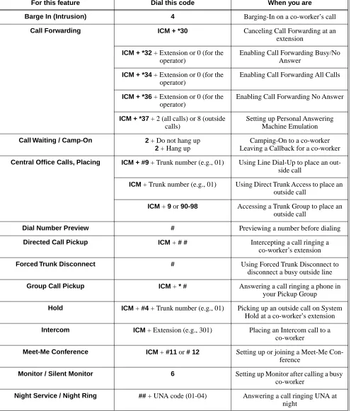
Table 1: Dial Codes (by Feature)
For this feature Dial this code When you are
Barge In (Intrusion) 4 Barging-In on a co-worker’s call Call Forwarding ICM + *30 Canceling Call Forwarding at an
extension ICM + *32 + Extension or 0 (for the
operator)
Enabling Call Forwarding Busy/No Answer
ICM + *34 + Extension or 0 (for the operator)
Enabling Call Forwarding All Calls
ICM + *36 + Extension or 0 (for the operator)
Enabling Call Forwarding No Answer
ICM + *37 + 2 (all calls) or 8 (outside calls)
Setting up Personal Answering Machine Emulation Call Waiting / Camp-On 2 + Do not hang up
2 + Hang up
Camping-On to a co-worker Leaving a Callback for a co-worker Central Office Calls, Placing ICM + #9 + Trunk number (e.g., 01) Using Line Dial-Up to place an
out-side call
ICM + Trunk number (e.g., 01) Using Direct Trunk Access to place an outside call
ICM + 9 or 90-98 Accessing a Trunk Group to place an outside call
Dial Number Preview # Previewing a number before dialing Directed Call Pickup ICM + # # Intercepting a call ringing a
co-worker’s extension Forced Trunk Disconnect # Using Forced Trunk Disconnect to
disconnect a busy outside line Group Call Pickup ICM + * # Answering a call ringing a phone in
your Pickup Group
Hold ICM + #4 +Trunk number (e.g., 01) Picking up an outside call on System Hold at a co-worker’s extension Intercom ICM + Extension (e.g., 301) Placing an Intercom call to a
co-worker
Meet-Me Conference ICM + #11 or # 12 Setting up or joining a Meet-Me Con-ference
Monitor / Silent Monitor 6 Setting up Monitor after calling a busy co-worker
Charts and Illustrations
Paging *1 + Page zone (1-7 or 0 for All Call) Making an internal Paging announce-ment
Park ICM + ** + System Park Orbit (60-69) Parking or retrieveing a call from Sys-tem Park Orbit
ICM + ** + Extension (e.g., 301) Using Personal Park to Park or retrieve a call at a co-workers extension Removing Trunks and Extensions
From Service
ICM + #40 + Extension (e.g., 301) or trunk (e.g., 401) + 4 (to return) or 6
(to remove)
Removing or returning an extension or trunk to service
Selectable Display Messaging ICM + *38 + Message (00-16) + Hold + Add additional digits + Hold
Enabling a Selectable Display Message
Speed Dial ICM + ## + System bin (200-299) or Personal bin (701-720)
Dialing a System or Personal Speed Dial number
Transfer ICM + Extension (e.g., 301) Transferring a call to a co-worker’s extension
ICM + Extension (e.g., 301) + MW Transferring a call to a co-worker’s mailbox
Trunk (Line) Queuing / Trunk Call-back
2 Queuing or leaving a Callback for a busy trunk
Voice Mail ICM + MW Calling your mailbox ICM + Extension (e.g., 301) + MW Transferring a call to a co-worker’s
mailbox ICM + *37 + 2 (all calls) or 8 (outside
calls)
Setting up Personal Answering Machine Emulation
ICM + *30 Canceling Personal Answering Machine Emulation
Voice Over 9 Initiating a Voice Over to a busy exten-sion (after hearing busy/ring tone) Table 1: Dial Codes (by Feature)
Charts and Illustrations
DS1000/2000 Software Manual Chapter 1: Features ◆ 17
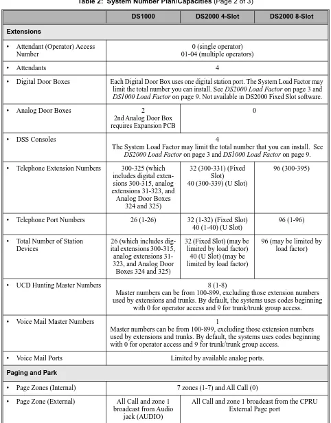
Table 2: System Number Plan/Capacities (Page 1 of 3)
DS1000 DS2000 4-Slot DS2000 8-Slot
System Options
• Classes of Service 1-15
(COS 1 normally reserved for attendants)
• Conference 32 simultaneous users in Conference (total of all Conferences system-wide) 8 simultaneous Conferences maximum
8 parties maximum in any one Conference • Extension Hunting (ACD/
UCD) Master Numbers
8
• Extension Hunting Groups 8 (1-8)
• Group Call Pickup Groups 8 (1-8, 0 = unassigned) • Privacy Release Groups 16 (1-16, 0 = unassigned) • Speed Dial, Personal 20 bins at each extension (701-720)
See Speed Dial (page 332) for additional information on Speed Dial capacities. • Speed Dial. System 10 (20-29), 100 (200-299), 1000 (2000-2999)
See Speed Dial (page 332) for additional information on Speed Dial capacities.
• Tenant Groups 1
• Timeslots Non-blocking
• Toll Restriction Levels 7 (1-7, 0 = no restriction) Trunks
• Direct Trunk Access Codes 401-406 401-416 (Fixed Slot) 401-424 (U Slot)
401-448
• Line Dial Up Codes #901-#906 #901-#916 (Fixed Slot) #901-#924 (U Slot)
#901-#948
• Ring Groups 8 (1-8)
0 = No assignment
Ring Group master numbers can be 100-299, 332-400, or 417-899. They can-not be in the extension (300-395 in DS2000 or 300-325 in DS1000) or trunk (401-448 in DS2000 or 401-406 in DS1000) number range. By default, the systems uses codes beginning with 0 for operator access and 9 for trunk/trunk
group access.
• Trunk Group Access Codes 90-98
• Trunk Groups 9 (0-8)
• Trunk Ports 6 (1-6)
Trunks 4-6 require the Expansion Board.
16 (1-16) (Fixed Slot) 24 (1-24) (U Slot)
Charts and Illustrations
Extensions
• Attendant (Operator) Access Number
0 (single operator) 01-04 (multiple operators)
• Attendants 4
• Digital Door Boxes Each Digital Door Box uses one digital station port. The System Load Factor may limit the total number you can install. See DS2000 Load Factor on page 3 and DS1000 Load Factor on page 9. Not available in DS2000 Fixed Slot software.
• Analog Door Boxes 2
2nd Analog Door Box requires Expansion PCB
0
• DSS Consoles 4
The System Load Factor may limit the total number that you can install. See DS2000 Load Factor on page 3 and DS1000 Load Factor on page 9.
• Telephone Extension Numbers 300-325 (which includes digital exten-sions 300-315, analog extensions 31-323, and Analog Door Boxes
324 and 325)
32 (300-331) (Fixed Slot)
40 (300-339) (U Slot)
96 (300-395)
• Telephone Port Numbers 26 (1-26) 32 (1-32) (Fixed Slot) 40 (1-40) (U Slot)
96 (1-96)
• Total Number of Station Devices
26 (which includes dig-ital extensions 300-315, analog extensions 31-323, and Analog Door
Boxes 324 and 325)
32 (Fixed Slot) (may be limited by load factor)
40 (U Slot) (may be limited by load factor)
96 (may be limited by load factor)
• UCD Hunting Master Numbers 8 (1-8)
Master numbers can be from 100-899, excluding those extension numbers used by extensions and trunks. By default, the systems uses codes beginning
with 0 for operator access and 9 for trunk/trunk group access.
• Voice Mail Master Numbers 1
Master numbers can be from 100-899, excluding those extension numbers used by extensions and trunks. By default, the systems uses codes beginning with 0 for operator access and 9 for trunk/trunk group access.
• Voice Mail Ports Limited by available analog ports. Paging and Park
• Page Zones (Internal) 7 zones (1-7) and All Call (0) • Page Zone (External) All Call and zone 1
broadcast from Audio jack (AUDIO)
All Call and zone 1 broadcast from the CPRU External Page port
Table 2: System Number Plan/Capacities (Page 2 of 3)
Charts and Illustrations
DS1000/2000 Software Manual Chapter 1: Features ◆ 19
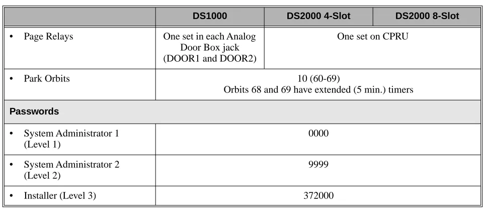
• Page Relays One set in each Analog Door Box jack (DOOR1 and DOOR2)
One set on CPRU
• Park Orbits 10 (60-69)
Orbits 68 and 69 have extended (5 min.) timers Passwords
• System Administrator 1 (Level 1)
0000
• System Administrator 2 (Level 2)
9999
• Installer (Level 3) 372000
Table 2: System Number Plan/Capacities (Page 3 of 3)
Charts and Illustrations
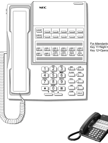
Figure 1: 22-Button Display Telephone (Fixed Slot)
1
2
3
4
5
6
7
8
9
0
ABC DEF
MW ICM
FLASH DND
DIAL MIC
LND SPK
CONF HOLD GHI JKL MNOMNO
PQRS TUV
OPER
VOL
WXYZ CLEAR
CHECK
80000 - 21A
LINE 1 LINE 2 LINE 3 LINE 4 LINE 5 LINE 6
LINE 7 LINE 8 LOOP 0FIXED LOOP 0FIXED TIMERAUTO PAGEALL
BIN 1 BIN 2 BIN 3 BIN 4 BIN 5
BIN 6 BIN 7 BIN 8 BIN 9 BIN 10
For Attendants: Key 11=Night Key
Charts and Illustrations
DS1000/2000 Software Manual Chapter 1: Features ◆ 21
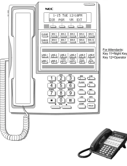
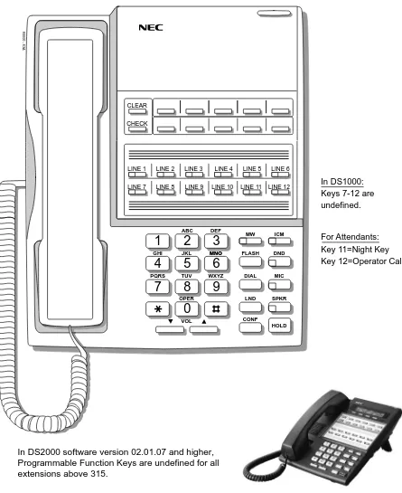
Figure 2: 22-Button Display Telephone (U Slot and DS1000)
1
2
3
4
5
6
7
8
9
0
ABC DEF
MW ICM
FLASH DND
DIAL MIC
LND SPK
CONF HOLD GHI JKL MNOMNO
PQRS TUV
OPER
VOL
WXYZ CLEAR
CHECK
80000 -62A
LINE 1 LINE 2 LINE 3 LINE 4 LINE 5 LINE 6
LINE 7 LINE 8 LINE 9 LINE 10 LINE 11 LINE 12 BIN 1 BIN 2 BIN 3 BIN 4 BIN 5
BIN 6 BIN 7 BIN 8 BIN 9 BIN 10
For Attendants: Key 11=Night Key
Key 12=Operator Call Key In DS1000:
Keys 7-12 are undefined.
Charts and Illustrations
Figure 3: 22-Button Standard Telephone (Fixed Slot)
1
2
3
4
5
6
7
8
9
0
ABC DEF
MW ICM
FLASH DND
DIAL MIC
LND SPKR
CONF HOLD GHI JKL MNOMNO
PQRS TUV
OPER
VOL
WXYZ CLEAR
CHECK
80000 - 22A
LINE 1 LINE 2 LINE 3 LINE 4 LINE 5 LINE 6
LINE 7 LINE 8 LOOP 0FIXED LOOP 0FIXED TIMERAUTO PAGEALL
For Attendants: Key 11=Night Key
Charts and Illustrations
DS1000/2000 Software Manual Chapter 1: Features ◆ 23
Figure 4: 22-Button Standard Telephone (U Slot and DS1000)
1
2
3
4
5
6
7
8
9
0
ABC DEF
MW ICM
FLASH DND
DIAL MIC
LND SPKR
CONF HOLD GHI JKL MNOMNO
PQRS TUV
OPER
VOL
WXYZ CLEAR
CHECK
80000 - 63A
LINE 1 LINE 2 LINE 3 LINE 4 LINE 5 LINE 6
LINE 7 LINE 8 LINE 9 LINE 10 LINE 11 LINE 12
For Attendants: Key 11=Night Key
Key 12=Operator Call Key In DS1000:
Keys 7-12 are undefined.
Charts and Illustrations
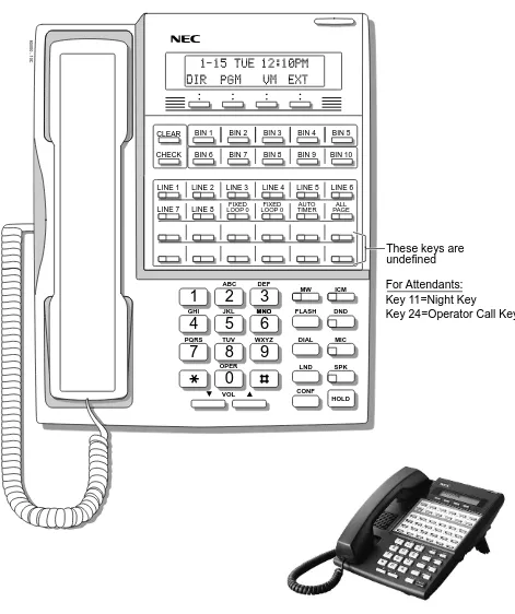
Figure 5: 34-Button Display Telephone (Fixed Slot)
1
2
3
4
5
6
7
8
9
0
ABC DEF
MW ICM
FLASH DND
DIAL MIC
LND SPK
CONF HOLD GHI JKL MNOMNO
PQRS TUV
OPER
VOL
WXYZ CLEAR
CHECK
80000 - 10C
LINE 1 LINE 2 LINE 3 LINE 4 LINE 5 LINE 6
LINE 7 LINE 8
BIN 1 BIN 2 BIN 3 BIN 4 BIN 5
BIN 6 BIN 7 BIN 8 BIN 9 BIN 10
These keys are undefined
For Attendants: Key 11=Night Key
Key 24=Operator Call Key FIXED
Charts and Illustrations
DS1000/2000 Software Manual Chapter 1: Features ◆ 25
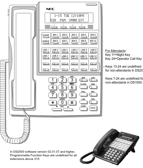
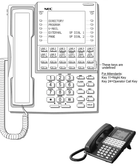
Figure 6: 34-Button Display Telephone (U Slot and DS1000)
1
2
3
4
5
6
7
8
9
0
ABC DEF
MW ICM
FLASH DND
DIAL MIC
LND SPK
CONF HOLD GHI JKL MNOMNO
PQRS TUV
OPER
VOL
WXYZ CLEAR
CHECK
80000 - 64A
LINE 1 LINE 2 LINE 3 LINE 4 LINE 5 LINE 6
LINE 7 LINE 8
BIN 1 BIN 2 BIN 3 BIN 4 BIN 5
BIN 6 BIN 7 BIN 8 BIN 9 BIN 10
Keys 13-24 are undefined for non-attendants in DS2000.
Keys 7-24 are undefined for non-attendants in DS1000.
LINE 9 LINE 10 LINE 11 LINE 12
For Attendants: Key 11=Night Key
Key 24=Operator Call Key
Charts and Illustrations
Figure 7: 34-Button Super Display Telephone (Fixed Slot)
1
2
3
4
5
6
7
8
9
0
ABC DEF
MW ICM
FLASH DND
DIAL MIC
LND SPKR
CONF HOLD GHI JKL MNO
PQRS TUV
OPER
VOL
WXYZ
80000 - 23A
CHECK CLEAR
LINE 1 LINE 2 LINE 3 LINE 4 LINE 5 LINE 6
LINE 7 LINE 8
These keys are undefined FIXED
LOOP 0 LOOP 0FIXED TIMERAUTO PAGEALL
For Attendants: Key 11=Night Key
Charts and Illustrations
DS1000/2000 Software Manual Chapter 1: Features ◆ 27
Figure 8: 34-Button Super Display Telephone (U Slot and DS1000)
1
2
3
4
5
6
7
8
9
0
ABC DEF
MW ICM
FLASH DND
DIAL MIC
LND SPKR
CONF HOLD GHI JKL MNO
PQRS TUV
OPER
VOL
WXYZ
80000 - 65A
CHECK CLEAR
LINE 1 LINE 2 LINE 3 LINE 4 LINE 5 LINE 6
LINE 7 LINE 8
Keys 13-24 are undefined for non-attendants in DS2000.
Keys 7-24 are undefined for non-attendants in DS1000.
LINE 9 LINE 10 LINE 11 LINE 12
For Attendants: Key 11=Night Key
Key 24=Operator Call Key
Charts and Illustrations
Figure 9: 24-Button DSS Console
80000 - 25
300 312
301 313
302 314
303 315
304 316
305 317
306 318
307 319
308 320
309 321
310 322
Charts and Illustrations
DS1000/2000 Software Manual Chapter 1: Features ◆ 29
Figure 10: 110-Button DSS Console (Fixed Slot)
80000 - 24
300 301 302 303 304 305 306 307 308 309
310 311 312 313 314 315 316 317 318 319
320 321 322 323 324 325 326 327 328 329
330 331 LINE 1 LINE 2 LINE 3 LINE 4 LINE 5 LINE 6 LINE 7 LINE 8
202 203 204 205 206 207 208 209 701 702
703 704 705 706 707 708 709 710 711 712
713 714 715 716 717 718 719 720 PG 0 PG 1
PK 0 PK 1
These keys are undefined
Charts and Illustrations
Figure 11: 110-Button DSS Console (U Slot)
80000 - 66
300 301 302 303 304 305 306 307 308 309
310 311 312 313 314 315 316 317 318 319 320 321 322 323 324 325 326 327 328 329 330 331 332 333 334 335 336 337 338 339
350 351 352 353 354 355 356 357 358 359
360 361 362 363 364 365 366 367 368 369
370 371 372 373 374 375 376 377 378 379
PAGE 1 PAGE 2 PAGE 3 PAGEALL
PARK 0 PARK 1 PARK 2 PARK 3 PARK 4 PARK 5 PARK 6 PARK 7 PARK 8 NIGHT
These keys are undefined
Charts and Illustrations
DS1000/2000 Software Manual Chapter 1: Features ◆ 31
80200 - 38
300 301 302 303 304 305 306 307 308 309
310 311 312 313 314 315 316 317 318 319
320 321 322 323 324 325
PAGE 1 PAGE 2 PAGE 3 PAGEALL
PARK 0 PARK 1 PARK 2 PARK 3 PARK 4 PARK 5 PARK 6 PARK 7 PARK 8 NIGHT
Hotlines to Extensions
Note: Blank keys are undefined.
2-OPX Module
2-OPX Module
Description
DS2000 Fixed Slot Available. See see Off-Premise Extensions / On-Premise SLT Extensions on page 274.
DS2000 U Slot
2500 Sets / Single Line Telephones
DS1000/2000 Software Manual Chapter 1: Features ◆ 33
2500 Sets / Single Line Telephones
Description
DS2000 Fixed Slot
Available. Refer to Off-Premise Extensions / On-Premise SLT Extensions on page 274 for more.
Account Codes
Account Codes
Description
Account Codes are user-dialed codes that help categorize and/or restrict trunk calls. Account Codes are from 2-10 digits long, using any combination of the digits 0-9. There are three types of Account Codes:
● Optional (Unforced Account Codes)
● Forced Account Codes
● Verified Account Codes
Optional (Unforced) Account Codes
Optional Account Codes allow a keyset extension user to enter an Account Code while placing a trunk call or any time while on a call. This type of Account Code is optional: the system does not require the user to enter it. If the keyset user is already talking on a trunk call, their conversation continues uninterrupted while they enter an Account Code.
Single line telephone users can only enter an Account Code while placing their trunk call.
Forced Account Codes
Forced Account Codes require an extension user to enter an Account Code every time they place a trunk call. If the user doesn’t enter the code, the system prevents the call. The system can require Forced Account Codes for all trunk calls, or just for toll calls (as determined by Toll Restriction programming). Note that Forced Account Codes do not pertain to incoming calls.
Verified Account Codes
With Verified Account Codes, the system compares the Account Code the user dials with a list of codes programmed into the Verified Account Code Table. If the Account Code is in the table, the call goes through (provided it is not prevented by an extension’s Toll Restriction programming). If the code is not in the table, the system prevents the call. Verified Account Codes, if enabled, apply only to Forced Account Codes.
Using Account Codes and Speed Dial
To simplify Account Code operation, Personal and System Speed Dial bins can contain Account Codes. Keep the following in mind when using Speed Dial and Account Codes:
● The Account Code can be either the first or last entry in the bin, and must be preceded and fol-lowed by the # character. For example, the Account Code 1234 must be entered as #1234#.
● The Program 0201 - # Key to Enter Account Codes (page 447) option must be enabled in sys-tem programming. In addition, the Program 0201 - Enable Account Codes in Speed Dial (2.01.07 or higher) (page 446) option must also be enabled.
● The Speed Dial bin can contain an Account Code followed by an outside number, or just the Account Code. The Account Code must be preceded and followed by a # entry. If the bin contains just the Account Code, the user must be sure to press the bin key before dialing the outside number.
DS2000 Fixed Slot Not available. DS2000 U Slot
Available. Requires software version 02.01.07 or higher. DS1000
Account Codes
DS1000/2000 Software Manual Chapter 1: Features ◆ 35
● If the system has Verified Account Codes enabled, the Account Code entered in the Speed Dial bin must match an entry in the Verified Account Code Table.
● If the Speed Dial bin does not contain an Account Code, the user must enter the Account Code manually. If Forced Account Codes are enabled, the system requires the user to enter the Account Code before it outdials the stored Speed Dial number.
● An extension user can preselect a trunk for a Speed Dial call.
Using Account Codes with Last Number Redial and Save
Last Number Redial and Save do not store Account Codes. This means that the user must manually enter an Account Code to have it included with a call dialed using Last Number Redial and Save. If Forced Account Codes are enabled, the system requires the user to enter the Account Code before it outdials the stored number saved by Last Number Redial or Save.
An extension user can preselect a trunk for a Last Number Redial or Save call.
Account Codes and Emergency Calls
Account Codes are never enforced for emergency (911 and 1+911) calls. Conditions
Do not use Account Codes that begin with 911 or 1911. Default Setting
Account Codes
Programming Guide
Step-by-step guide for setting up Account Codes (Page 1 of 2)
Step 1: Should users be able to store Account Codes in Speed Dial bins?
• In Program 0201 - Enable Account Codes in Speed Dial (2.01.07 or higher) (page 446), enter Y.
• In Program 0201 - Enable Account Codes in Speed Dial (2.01.07 or higher) (page 446), enter N. Any Account Codes stored in Speed Dial bins dial out as part of the stored number.
Step 2: While on an outside call, should an extension user be able to dial # to enter an Account Code?
• In Program 0201 - # Key to Enter Account Codes (page 447), enter Y.
• In Program 0201 - # Key to Enter Account Codes (page 447), enter N.
Step 3: Should Account Code entries be hidden (i.e., replaced by * characters) on each tele-phone’s display?
• In Program 0201 - View Account Codes (page 447), enter N.
• In Program 0201 - View Account Codes (page 447), enter Y.
Step 4: Should a keyset have an Account Code key to simplify entering Account Codes?
• In Program 1701 - Programmable Function Key Assignments (page 517), enter 26 to assign a key as an Account Code key.
• In Program 1701 - Programmable Function Key Assignments (page 517), do not assign a key with code 26.
If yes
If no
If yes
If no
If yes
If no
If yes
Account Codes
DS1000/2000 Software Manual Chapter 1: Features ◆ 37
Step 5: Should an extension have Forced Account Codes (i.e., be required to enter an Account Code while placing a call)?
• In Program 0101 - Forced Account Codes (page 443), enter Y.
• Program 1801 - Extension Class of Service Assignment (page 533), assign Class of Service to extensions.
• In Program 0101 - Forced Account Codes (page 443), enter N.
• Program 1801 - Extension Class of Service Assignment (page 533), assign Class of Service to extensions.
Step 6: Should an extension have Forced Account Codes just for long distance (toll) calls?
• In Program 0101 - Forced Account Codes for Toll Calls Only (page 443), enter Y.
• In Program 0201 - Account Code Toll Level (page 447), enter the toll level (0-7) the system will use to determine toll calls. See Forced Account Codes Programming on page 38 for more on setting this up.
• Program 1801 - Extension Class of Service Assignment (page 533), assign Class of Service to extensions.
• In Program 0101 - Forced Account Codes for Toll Calls Only (page 443), enter N.
• Program 1801 - Extension Class of Service Assignment (page 533), assign Class of Service to extensions.
Step 7: Should an extension have Verified Account Codes (i.e., be required to enter an Account Code from the Verified Account Codes Table while placing a call)?
• In Program 0101 - Verify Account Codes (page 443), enter Y.
• In Program 1201 - Verified Account Codes Table (page 515), enter codes into the Verified Account Codes table.
• In Program 1801 - Extension Class of Service Assignment (page 533), assign Class of Service to extensions.
• In Program 0101 - Verify Account Codes (page 443), enter N.
• Program 1801 - Extension Class of Service Assignment (page 533), assign Class of Service to extensions.
Step-by-step guide for setting up Account Codes (Page 2 of 2)
Account Codes
Programming List
General Account Codes Programming
Program 0201 - Enable Account Codes in Speed Dial (2.01.07 or higher) (page 446)
Enable (Y) this option if users should be able to store Account Codes in Speed Dial bins. This causes the stored Account Code to properly display in the SMDR report Account column. If you disable (N) this option, Account Codes stored in Speed Dial bins dial out as part of the stored number and display in the SMDR report Number Dialed column. They will not display in the Account column. This option is disabled by default.
Program 0201 - # Key to Enter Account Codes (page 447)
Use this option to enable (Y) an extension user to dial # to enter an Account Code while on an outside call. If disabled (N), the extension user can only enter an Account Code by pressing the Account Code soft key or a uniquely programmed Account Code Programmable Function Key. This option is disabled by default.
Program 0201 - View Account Codes (page 447)
Use this option to show or hide the Account Codes a user enters on their telephone’s display. If enabled (Y), the dialed Account Codes show on the display. This may be a security risk, since a co-worker can easily read the telephone display as the user enters their Account Code. If disabled (N), Account Codes are shown as * characters on the telephone display. This option is disabled by default.
Program 1701 - Programmable Function Key Assignments (page 517)
Use this option to assign an Account Code Programmable Function Key to a keyset (code 26). There are no Account Code Programmable Function Keys assigned by default. The Account Code Programmable Function Key is not available on DSS Consoles.
Optional (Unforced) Account Codes Programming
Optional Account Codes are always available without programming.
Forced Account Codes Programming
Program 0101 - Forced Account Codes (page 443)
Use this option to enable (Y) or disable (N) Forced Account Codes. If disabled, Optional Account Codes are still available. This option is disabled by default.
Program 0101 - Forced Account Codes for Toll Calls Only (page 443)
● Use this option to enable (Y) Forced Account Codes only for toll (long distance) calls. If disabled (N), Forced Account Codes apply to all outgoing trunk calls. This option is dis-abled by default (i.e., Forced Account Codes, if endis-abled, apply to all outgoing trunk calls).
● The system identifies toll calls according to the settings in Program 0201 - Account Code Toll Level (page 447) programming below.
● If Program 0101 - Forced Account Codes (page 443) is disabled, the Program 0101 - Forced Account Codes for Toll Calls Only (page 443) option has no effect.
Program 0201 - Account Code Toll Level (page 447)
If Program 0101 - Forced Account Codes for Toll Calls Only (page 443) is enabled, use this option to differentiate toll calls from local calls for Account Code purposes. If you enter 0 for this option, toll calls are any calls the user dials that begin with 0 or 1. If you enter a toll level for this option (1-7), the system uses the toll level options programmed in Program 0601 - Toll Restriction Level (page 489) for that level to determine if the call is local or toll.
● If the toll level is set to deny the call, it is considered to be a long distance call and the sys-tem requires that the user must have entered an Account Code.
● If the toll level permits the call, it is considered to be a local call and no Account Code entry is required.