A Survey of Microstrip Patch Antenna for
MIMO
1
Nagaraj Hanchinamani,
2Dr. C.R. Byrareddy
1Ph.D Scholar, Dept. of Electronics Engineering, Jain University, Bangalore, India 2Professor, Dept. of Electronics & Co mmunication Engineering, BIT, Bangalore, India
ABSTRACT: Gradual improve ment of design of microstrip patch antenna for mu ltip le inputs and mult iple output system researcher have been urged to deploy wideband antenna to enhance the features of MIMO. MIMO technology has attracted consideration in wire less communicat ions, because it present significant increases in data throughput and link range without requiring extra bandwidth or transmit power, higher spectral efficiency and reduced fading , A few techniques can be applied to improve the microstrip antenna bandwidth. These include introducing parasitic ele ment either in coplanar or stack configuration, increasing the substrate thickness and modifying the shap e of a patch by inserting slots and explo re new possibilit ies of new wideband mic rostrip patch antenna for ne xt generation.
KEYWORDS: MIM O, MICROSTRIP PATCH ANTENNA,LTE
I. INTRODUCTION
Multiple transmit and multip le receive antennas has emerged as one of the most significant t echnical brea kthroughs in next generation wire less communicat ions. MIMO is considered a key technology for improving the throughput of future wireless broadband data systems; MIMO is the use of multip le antennas at both the transmitter and receiver to improve communicat ion performance. MIMO technology has attracted attention in wire less communicat ions, because it offers significant increases in data throughput and link range without requiring additional bandwidth or transmit power, higher spectral efficiency and reduced fading. Because of these properties, M IMO is an important part of modern wire less communicat ion standards such as IEEE 802.11n (W ifi), IEEE 802.16e (W iMAX), 3GPP Long Term Evolution (LTE), 3GPP HSPA +, 4G and 5G systems to come.
MIMO systems e mploying wideband microstrip patch antenna is the fastest growing field of technology which has captured the attention of day to day life in the future Wireless Commun ications due to their tre mendous spectral efficiency. The most pressing problems in Wireless Commun ications will be spectral efficiency and interference in the next decade. Wireless Internet, mobile video and data communicat ion will push the spectrum to its limitations. In the same way interference with other services will be increased by the increasing use of spectrum. Taking this into the account the most prominent task is to increase the spectral effic iency and to introduce measures for interference reduction. MIMO systems promise to reach very large data rates and there with high spectral effic iencies.
The role of microstrip antennas in the current wire less scenario and diffe rent types of mic rostrip antennas that are used in the design of MIMO systems are presented. These antennas are narrowband ele ments, which limits their application in modern high data rate wireless systems. The mutual coupling is another major issue that degrades the performance of the MIMO systems, which arises due to the smaller spacing between the antennas.
II. HIS TORY OF MICROS TRIP PATCH ANTENNA
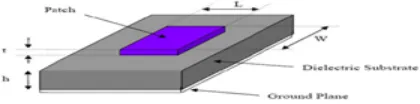
introduced in the 1950s. Ho wever, this concept had to wait for about 20 years to be realized a fter the development of the printed circuit board (PCB) technology in the 1970s. Since then, microstrip antennas are the most common types of antennas with wide range of applications due to their apparent advantages of l ight we ight, low profile , low cost, planar configuration, easy of conformal, superior portability, suitable for array with the ease of fabrication and integration with microwave monolithic integrate circuits (MMICs).They have been widely engaged for the civilian and military applicat ions such as radio-frequency identification (RFID), broadcast radio, mobile systems, global positioning system (GPS), telev ision, mult iple -input mu ltip le-output (MIMO) systems, vehicle co llision avoidance system, satellite co mmu nications, surveillance systems, direct ion founding, radar systems, re mote sensing, missile guidance, and so on. Microstrip antenna in its simplest design is shown in Figure 1. It consists of a radiating patch on one side of dielectric substrate (Єr≤10), with a ground plane on other side.
Figure 1: Microstri p antenna configur ation
A microstrip patch antenna (MPA) consists of a conducting patch of any non -planar or planar geo metry on one side of a dielectric substrate and a ground plane on other side. It is a printed resonant antenna for narrow-band micro wave wireless links requiring semi-he mispherical coverage. Due to its planar configuration and ease of integration with microstrip technology, the microstrip patch antenna has been deeply. The rectangular and circula r patches are the basic and most commonly used microstrip antennas.
III.FEEDING TECHNIQUES
Microstrip patch antennas can be fed by a variety of methods. The methods can be classified into two categories contacting and non-contacting. In the contacting method, the RF power is fed directly to the radiating patch using a connecting ele ment such as a microstrip line. In the non contacting scheme, e lectro magnetic fie ld coupling is done to transfer power between the mic rostrip line and the radiating patch. The four most popular feed techniques are
Microstrip Line Feed
Figure 2 Micr ostri p Line Fee d
Coaxial Probe Feed
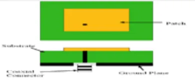
The Coa xia l probe feed is a very co mmon technique u sed for feed ing Microstrip patch antennas. The inner conductor of the coaxia l connector extends through the dielectric and is soldered to the radiating patch, while the outer conductor is connect ed to the ground plane. The main advantage of this type of feeding scheme is that the feed can be placed at any desired location inside the patch in order to match with its input impedance.
Figure 3 Coaxial probe Fee d
Proximity coupled Feed
This type of feed technique is also called as the electromagnetic coupling scheme. Two dielectric substrates are used such tha t the feed line is between the two substrates and the radiating patch is on top of the upper substrate. The main advantage of t his feed technique is that it eliminates spurious feed radiation and provides very high bandwidth (as high as 13%) due to overall increase in the thickness of the microstrip patch antenna. This method is advantageous to reduce harmonic radiation of microstrip patch antenna imp le mented in a mu ltilayer substrate.
Figure 4 Pr oximi ty couple d Fee d
Aperture coupled feed
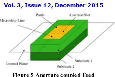
Figure 5 Aperture c ouple d Fee d
IV. CURRENT CONFIGURED PATCH ANTENNAS TECHNOLOGY
Ha mid re za Da lili [2] described a new planar microstrip ultra wideband antenna for multi input and multi output applications. To reduce the interference proble ms, UW B antennas with various band notch properties have used. His proposed antenna consists of hexagonal patch and a partial ground which the both of its edge have been etched. And using semi c ircu lar slot in diffe rent position to increase the bandwidth with semi-c ircula r slot become better on the upper band with creating a resonant frequency at nearly 16.3Ghz. Also two ele ment array of such antenna in four different configurations for MIMO applications were ana lyzed. Slot important roles to create the notches but leads a disad vantage i.e when this type of antenna is integrated with printed circu it board, the RF c ircuit cannot be very close to ground plane.
Ghyda'a M et.a l [3] focuses on to enhance the bandwidth of the printed slot antenna with center E-shaped patch the overall size of this antenna is 37x37 mm2 mounted on top of FR4 dielectric materia l with relative permitt ivity of Er =4.4, and fed by a microstrip feed line printed on the bottom of the dielectric material. Fro m the simulat ion results, it has been found that th e antenna is able to operate at wide BW ranging fro m (2.35 -6.91) GHz.
K. Jagadeesh Babu et.al [4] have been presented a two element MIM O system is using a mu lti slot patch antenna employing orthogonal polarization diversity. The proposed antenna array reson ates at dual band offering an improved bandwidth of 16% with return loss and mutual coupling < -27d B. These characteristics are well suited for all 4G MIMO applications. The proposed MIMO system, the separation between the elements is 10 mm which is 0.17λ. This separation is much smaller compared to the conventional arrays which are separated by 0.5λ. The prop osed MIMO array exh ibits improved return loss (s11) and e xcellent isolation properties (S12) at the resonant frequencies 5.35 GHz and 5.81GHz. The antenna gives the -10dB bandwidth of 16%. At the resonant frequencies the values of S11 a re -27dB and -32dB respectively, which gives good impedance matching for the antenna.
Re zaul Azim et all [5] described a compact planar antenna operating at a frequency range of 3–16 GHz is presented for wideband applications. The antenna is composed of a square patch fed by a mic rostrip line and a partia l ground plane with a rectangular slot. The proposed antenna is very easy to be integrated with microwave circuitry for low manufacturing cost. The Expe rimental result shows that the measured impedance bandwidth (VSWR ≤ 2) of the proposed antenna is 3.2-15.44 GHz, with a notch fro m 4.7 to 5.8 GHz.
Arvind Kumar [7] et al focused on novel approach for gain enhancement in microstrip patch antennas using metallic rings. The design forces conversion of the surface wave energy into the space wave energy by scattering of surface waves. Electric field intensity of antenna with ring is eight to nine times higher as compare to antenna without ring and from the several simulations it is observed that whenever there is higher field intensity, antenna exhibits higher gain and the patch antenna with metallic rings achieves average gain of 10.88 dB in the frequency range of 5.5– 6 GHz Hence patch with meta llic ring have higher average gain as compared to patch without metallic ring.
A.A. Asaker[8]et al design of a wideband microstrip patch antenna for LTE-A. The bandwidth of the conventional patch is enlarged by using etched slots at the antenna patch. The designed antenna has been fabricated by using thin film and photolithographic technique and has been measured by using the Vector Net work Analyze r. Isolation between the mic rostrip ele ments is increased by placing metal structure between antenna elements. For mo re isolation between antenna elements, Slotted Ground Plane SGP is utilized.
V. DIFFER ENT CONFIGURATIONS TO REDUC E THE MUTUAL COUPLING FOR MIMO IN THE PRES ENT LITERATURE
In Multiple inputs multip le output (MIMO) system the mutual coupling is the ma jor issue that degrades the performance of the MIMO system and arises due to smalle r space between the antennas. Researcher have been urged to deploy diffe rent techniques to reduceMutual coupling is by including the increasing space between the antenna, polarization diversity and serpentine structure between antennas below tables shows the current technology used to reduce the mutual coupling between the MIMO system
Ref paper
Proposed Geo metry of Antenna
Methods to reduce Mutual coupling Resonance Frequency Mutual Coupling Reduction
Edge to Edge Spacing
[9] Simp le mic rostrip patch ele ment in between the antennas
6.8 GHz reduced to around
−33 dB
0.45λ0 (20mm)
[6] Modified Se rpentine structure (MSS)
2.45 GHz -34dB 0.05λ0 (6mm)
[10] Metamateria l with Split Ring Resonators(SRR)
2.38GHz < -25 dB 0.125λ0 (16mm),
[8] Metal strip between two ele ments and slotted ground plane(SGP),orthogonally polarized
2.522GHz -17dB to -22 dB
VI. CONCLUS ION
This paper is a survey on the technological advancements in microstrip patch antenna over 40 years. A lot of research work is going on microstrip antenna for its better utilization in the ne xt generation wireless communicat ion . MIM O is considered a key technology for imp roving the throughput of future wire less broadband data systems. Many techniques are coming into e xistence by compensating the gain and bandwidth o f the Microstrip Antenna. Survey shows that to enhance the features of microstrip patch antenna and enhance the bandwidth by using techniques such as introducing parasitic ele ment either in coplanar or stack configuration, increasing the substrate thicknes s and modifying the shape of a patch and inserting slots to explore new possibilities of new wideband microstrip patch antenna to enhance the features of MIMO and next generation
REFERENCES
[1]C. A. Balanis, “ Antenna Theory, Analysis and Design” John Wiley & Sons, Inc, New York 1997.
[2] Hamid Reza Dalili., “Design of New Compact Ultra Widband Microstrip antenna for MIMO application”. International journal of Natural and Engineering Science 7(2),pp no 22-26,2013.
[3] Ghyda'a M Al-Maani and Mohamed K Abdelazeez., “ Enhancement of Slot Antenna Parameters for Wideband Applications’’ Antennas ” International Journal of Electrical, Computer, Electronics and Communication Engineering Vol: 8, No: 6, pp-945-948, 2014.
[4] K. Jagadeesh Babu, Dr.K.Sri Rama Krishna, Dr.L.Pratap Reddy “A Multi Slot Patch Antenna for 4G MIMO Communications” ,International Journal of Future Generation Communication and Networking Vol. 4, No . 2, June, pp.105-112, 2011.
[5] Rezaul Azim , Mohammad T ariqul Islam ,Norbahiah Misran, “Printed Planar Antenna for Wideband Applications”, Journal of Infrared, Millimeter and T erahertz Waves, 31:969-978, 2010.
[6] Henridass Arun, Aswathy K. Sarma, Malathi Kanagasabai, “Deployment of Modified Serpentine Structure for Mutual Coupling Reduction in MIMO Antennas”, IEEE Antennas and wireless propagation letters, vol. 13, pp: 277-280, 2014.
[7] Arvind Kumar, Mithilesh Kumar, “Gain Enhancement in Microstrip Patch Antennas Using Metallic Rings”, American Journal of Engineering. Research, Volume-3, Issue-7, pp: 117- 124, 2014
[8] A.A. Asaker, R.S. Ghoname, A.A. Zekry, “ Design of a Planar MIMO Antenna for LTE-Advanced”International Journal of Computer Applications (0975 – 8887)Volume12,april2015.
[9] Kamili J. Babu, Rabah W. Aldhaheri Mohammed Y. T alha and Ibrahim S. Alruhaili, Design of a Compact T wo Element MIMO Antenna System with Improved Isolation, Progress In Electromagnetics Research Letters, Vol. 48, 27–32, 2014.
[10] Nilam. T. Kadam, Kiran. S. Janwalkar, Anuja. A. Odhekar Application of Metamaterial to Improve Isolation Between T wo Mi crostrip Antennas,
International Journal of Engineering Research & T echnology ,Vol.3 Issue 5,May 2014
BIOGRAPHY
NAGARAJ HANCHINAMANI was born in Karnataka, India in 1988. He rece ived the B.E Degree in Electronics and Co mmunicat ion engineering and the M.Tech degree in Digital Co mmun ication and Networking fro m the Visvesvaraya Technological Un iversity, Belgau m in 2010 and 2012 respectively. He is currently working an Lecturer in Electronics & Co mmunicat ion engineering department at Govern ment Polytechnic Bankapura, Haveri. . He is pursuing PhD at Jain University Bangalore. His research interest is on Antennas design and Wireless communication.