IJEDR1402028
International Journal of Engineering Development and Research (www.ijedr.org)1466
[email protected], [email protected], [email protected] ________________________________________________________________________________________________________ Abstract—Composite laminated materials have been increasingly used in a various industrial field. So predicting and preventing failures of composites becomes impotent aspect now days. To minimize cost and time pre-construction test of composite is always beneficial. Finite element analysis (FEA) is one of the important tool to predict failure of composite. In this paper finite element analysis (FEA) of composite is done and results are check with analytical results.Index Terms—finite element analysis (FEA), composite laminate beam,
I.INTRODUCTION
Composites are materials made from two or more constituent materials with significantly different physical or chemical properties, that when combined, produce a material with characteristics different from the individual components. The individual components remain separate and distinct within the finished structure. Each year, composites find their way into hundreds of new applications, from golf clubs and tennis rackets to jet skis, aircraft, missiles and spacecraft. Composite materials offer designers an increasing array of as a material and system solution. At the same time, composite cost trends are highly favourable, especially when the total cost of fabrication is considered. Processes such as pultrusion offer the means to convert composite materials into finished products in a single trip through the machinery. Composite sheet moulding compounds allow the formation of complete automobile skin panels in a single stroke of a press.
Reason for use:
Stronger and stiffer than metals on a density basis Capable of high continuous operating temperatures Highly corrosion resistant
Electrically insulating properties are inherent in most composites Tailorable thermal expansion properties
Exceptional formability and durability with Low investment in fabrication equipment Corrosion Resistance
Excellent Electromagnetic properties
Shock, impact, or repeated cyclic stresses can cause the laminate to separate at the interface between two layers, a condition known as de-lamination. Composites can fail on the microscopic or macroscopic scale. Compression failures can occur at both the macro scale or at each individual reinforcing fiber in compression buckling. Tension failures can be net section failures of the part or degradation of the composite at a microscopic scale where one or more of the layers in the composite fail in tension of the matrix or failure of the bond between the matrix and fibers.
To aid in predicting and preventing failures, composites are tested before and after construction. Pre-construction testing may use finite element analysis (FEA) for ply-by-ply analysis of curved surfaces and predicting wrinkling, crimping and dimpling of composites. Materials may be tested after construction through several non-destructive methods including ultrasonic, thermography, shearography and X-ray radiography. But most of the time Pre-construction testing are used. In this paper finite element analysis is uses to analyze composite laminate structure which are subjected to different working condition.
IJEDR1402028
International Journal of Engineering Development and Research (www.ijedr.org)1467
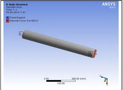
Fig 1 composite laminate beamThis composite laminate structure is fix at one end and 500KN tensile force is acting at other end. For this structure stress in deformation calculation is done both by analytically and with FEA.
II. ANALYTICAL SOLUTION
Wherever Times is specified, Times Roman or Times New Roman may be used. If neither is available on your word processor, please use the font closest in appearance to Times. Avoid using bit-mapped fonts. True Type 1 or Open Type fonts are required. Please embed all fonts, in particular symbol fonts, as well, for math, etc.
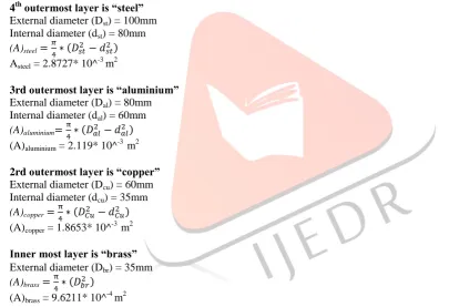
4th outermost layer is “steel”
External diameter (Dst) = 100mm Internal diameter (dst) = 80mm (A)steel ( )
Asteel = 2.8727* 10^-3 m2
3rd outermost layer is “aluminium”
External diameter (Dal) = 80mm Internal diameter (dal) = 60mm (A)aluminium ( )
(A)aluminium = 2.119* 10^-3 m2 2rd outermost layer is “copper”
External diameter (Dcu) = 60mm Internal diameter (dcu) = 35mm (A)copper ( )
(A)copper = 1.8653* 10^ -3
m2 Inner most layer is “brass”
External diameter (Dbr) = 35mm (A)brass ( )
(A)brass = 9.6211* 10^ -4
m2
Total force 500KN force acting on composite laminate panel is taken by each lamina by some amount. So that total force acting is equal to sum of force acting on each layer.
PTotal = Pal + Pst + Pcu +Pbr --- (1)
For finding out force taken by each layer we have to use compatibility condition.
[PL/AE]steel = [PL/AE]copper = [PL/AE]brass = [PL/AE]aluminium
IJEDR1402028
International Journal of Engineering Development and Research (www.ijedr.org)1468
cu cu cu cu
Pcu = 105.283*10^3 N
Force acting on aluminium layer,
3.7268 Pal + 1.4382 Pal + Pal + 0.6657 Pal = 500*10^3 Pal = 73.198*10^3 N
Force acting on brass,
5.5979 Pbr + 2.1603 Pbr + Pbr + 1.5020 Pbr = 500*10^3 Pbr = 48.733*10^3 N
Stress in each layer of composite laminate, Stress in 4th outermost layer (steel layer) = Pst/Ast
Stress in 4th outermost layer (steel layer) = 96.480 MPa
Stress in 3th outermost layer (aluminium layer) = 33.285 MPa
Stress in 2th outermost layer (copper layer) = 56.4423 MPa Stress in innermost layer (brass layer) = 50.6522 MPa
Deformation in composite laminate beam = PL/AE = 0.3859 mm
III.FEA SOLUTION
IJEDR1402028
International Journal of Engineering Development and Research (www.ijedr.org)1469
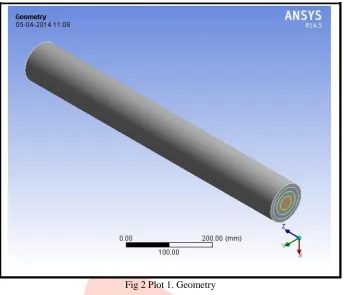
Fig 2 Plot 1. GeometryAfter construction of model we have to apply material property. As it is composite structure made up of different layer material so each layer have different material property. So create material file firstly for all material, then apply each material film to respective layer.
IJEDR1402028
International Journal of Engineering Development and Research (www.ijedr.org)1470
Fig 3 Plot 2. Loading and boundry conditionThen meshing of complete model is done.
Fig 4 Plot 3. Meshing model
IJEDR1402028
International Journal of Engineering Development and Research (www.ijedr.org)1471
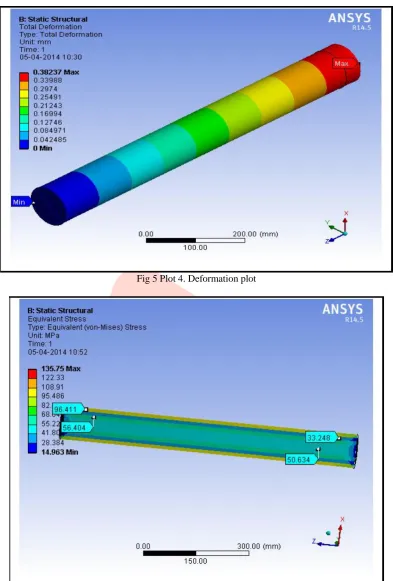
Fig 5 Plot 4. Deformation plotIJEDR1402028
International Journal of Engineering Development and Research (www.ijedr.org)1472
From comparison we can see that % of error in between analytical result and FEA result for stress are less than 0.2% and for deformation less than 1%. All the finite element analysis (FEA) result are closely matching with the analytical result. Hence result obtained from finite element analysis (FEA) are correct. Hence by using finite element analysis (FEA) we get the accurate result in minimum time and in minimum cost.REFERENCES
[1] P. Boresi, Richard J. Schmidt. ''Advanced Mechanics Of Materials'' 2009 [2] Ever J. Barbero. ''Finite Element Analysis of Composite Materials'' 2011 [3] E. J. Barber, introduction to composite material design.
[4] Wrinkling of sandwich column: comparison between finite element analysis and finite element solution. composite structures 53(2001)447-482